lEEE TRANSACTIONS ON MAGNETICS, VOL. 31, NO. 2 . MARCH 1995
I141
Improved Trellis-Coding for Partial-Response Channels L. Fredrickson’, R. Karabed2,J. Rae3,P. Siege12, H. Thapar’, R. Wood’ ‘IBM Storage Systems Division, San Jose, CA 95193 21BM Research Division, Almaden Research Center, San Jose, CA 95120 31BM Storage Systems Division, Rochester, MN 55901
-
Abstract New code design methods and Viterbi detector architectures are presented for high-rate trelliscoded partialresponse (TCPR) systems. The methods, which extend the matched-spectral-null (MSN) coding technique, use novel code constraints and time-varying detector trellis structures to reduce path memory requirements by as much as a factor of two, relative to previously reported codes, while retaining the other attractive features of MSN codes. The design methods and corresponding time-varying trellis structures are illustrated with several examples.
I. INTRODUCTION Trellis-coded partial-response (TCPR) has been experimentally shown to provide substantial performance advantages over PRML in digital magnetic recording systems. The prototype system evaluated in [ 11, [2] used a rate 8/10, matched-spectral-null (MSN) code [3] that provided a minimum squared-Euclidean distance 4, a factor of 2 greater than that of the baseline PRML system. Excellent closure between theory, analysis, and the experimental results was achieved. A detailed discussion of the VLSI chip used in the prototype can be found in ~41. From the point of view of hardware implementation, one of the most attractive features of the MSN code used in the prototype was the reduced-complexity, 2-way interleaved, Viterbi detector. On each of the evenlodd interleaves, the detector used a time-invariant, six-state trellis structure that tracks the running-digital-sum (RDS) of the code sequences, where the RDS of a binary sequence a = al, a2,... o,,is defined by
i= 1
However, this simplified detector trellis supports so-called quasicatastrophic (QC) sequences - infinite sequences that are represented by more than one distinct path through the trellis structure. These sequences give rise to Manuscript received August 5 , 1994. L. Fredrickson, now at Quantum Corp., Milpitas, CA 95035; R. Karabed, e-mall
[email protected], fax 408-927-3 520; P. Siegel, e-mail
[email protected], fax 408-927-3030; J. Rae and H. Thapar, now at DataPath Systems, Inc., Santa Ana, CA 92707, fax 714-5464245; R. Wood, fax 408-256-2653.
minimum-distance error events of unbounded length. This, in turn, would degrade the performance of the detector which, in practice, must use finite path memory. To prevent this performance degradation, referred to as QC error-propagation, the rate S/ 10 spectral-null code in [1],[2] was further constrained to avoid generating any QC sequences, a property shown in [3] to bound errorevent lengths. The maximum length of minimumdistance error events was thereby limited to 42 bits. The length-64 path memory implemented in the prototype system therefore provided ample time for the survivor paths to merge, ensuring that there would be virtually no negative impact on the system performance due to path memory truncation. Nevertheless, for reasons of hardware complexity, cost, power, and track format efficiency, it remains desirable to further reduce the path memory length required by a TCPR system. Imposing stricter constraints on the code, while retaining the time-invariant detector trellis structure, offers one approach, although t h s can complicate the code design, increase encoder/decoder complexity, and increase decoder error propagation. As an altemative, t h s paper introduces evolutionary TCPR design approaches, based upon the use of time-varying detector trellis structures, that produce codes suitable for practical magnetic recording systems. (We remark that timevarying structures also appeared in [SI in connection with another trellis-coding approach.) In Section 11, we provide background on MSN codes and elaborate upon the relationship between QC sequences and path memory length requirements. We then give an example to motivate the use of time-varying detector trellis structures to reduce the maximum length of minimum-distance error events. In Section 111, we describe several approaches that have been developed to overcome the problems associated with QC sequences, all involving Viterbi detection using time-vaqmg trellis structures. Examples of codes designed with most of these methods are discussed, including a new, rate 8/10 “partitioned” MSN code whose implementation and experimental performance evaluation is the subject of a companion paper [SI. Finally, in Section IV, we offer concluding remarks about the new code design techniques and their use in practical TCPR systems.
0018-9464/95$4.00 0 1995 IEEE
I142
11. BACKGROUND A N D MOTIVATION
In the remainder of this paper, we consider trellis codes for the dicode partial response channel, having system polynomial 1 - D . By interleaving, the codes can be adapted for use, more generally, on channels with system polynomials of the form 1 - DN,including the case of most practical interest, the Class-4 partial response channel, where N = 2. To illustrate the connection between QC sequences and detector path memory, and to provide motivation for the use of time-varying detector trelhses to reduce required path memory length, we will refer to the original rate 8/10 MSN code for the dicode channel disclosed in [7]. A . Quasicatastrophic Sequences and Detector Path Memory
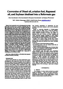
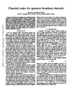
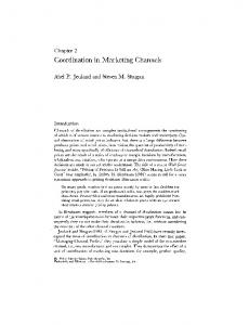
In the context of the binary-input dicode channel, the MSN coding approach is based upon the observation that a dc-free code (i.e., a code whose average power spectrum vanishes at zero frequency) doubles the minimum squared-Euclidean distance relative to the uncoded channel, increasing it from 2 to 4. This translates to an effective coding gain of approximately 3 dB, not accounting for the code rate penalty. A necessary and sufficient condition for a system of constrained sequences to have a spectral-null at zero frequency is that the sequences have bounded RDS values. Fig. 1 shows a so-called canonical state diagram that generates all binary sequences that assume at most seven RDS values. The states of the diagram effectively track the RDS values of the sequences generated by following paths through the directed graph. Using code construction methods for constrained systems, one can derive from the canonical diagram a hte-state-machine encoder for a rate 8/10 MSN code. A reduced-complexity trellis structure is derived not from the graph underlying the hte-state-machine encoder, but from the typically much simpler canonical diagram, which we will refer to on occasion as the RDS diagram. Fig. 2 shows one stage of one component of the 2-step (i.e. 2 symbols per edge) RDS trellis structure correspondmg to the RDS diagram of Fig. 1. The state labels correspond to those of Fig. 1, and the 2-symbol label for each edge is indicated to the left of the state from which the edge emanates. The detector trellis incorporates the spectral-null constraint represented in the RDS trellis, as well as the single-bit memory of the dicode channel. Fig. 3 shows the resulting 2-step detector trellis structure. The state labels are of the form s,f, where s is the RDS value and f is the dicode channel memory. For each edge, the channel input-symbol pair U and the corresponding channel output-symbol pair v are indicated as U/V to the left of the state from which the edge emanates.
1
1
1 1 1 1 f 1 2 i 5 6 7 0 0 0 0 0 0
Canonical diagram with 7 RDS states.
Figure 1.
-
00 01
10 11 00 01 10 11
-1
Figure 2.
RDS trellis (2-step) derived from Fig. 1 .
]
11/10 1°’1-1
Ffl
001-10 011-11 1010-1 11/00
oo/oo 01/01 1 011-1 11/10 oo/-10 01/-11 1010-1 11/00
oo/oo
01/01 1 011-1 11/10 001-10 011-11
Figure 3.
1
Detector trellis (2-step) for Fig. 2 on dicode channel.
The RDS trellis in Fig. 2 supports sequences that are generated by multiple, distinct paths, namely, the sequences corresponding to paths whch do not reach both state 1 and state 7. We say that these sequences are QC with respect to the RDS trellis. Sirmlarly, the detector trellis in Fig. 3 supports QC channel output sequences, and these correspond precisely to the QC sequences in Fig. 2. For example, the sequence 1 0 1 0 1 0 ..., generated in Fig. 2 by the three paths 1 1 1 ..., 3 3 3 ..., and 5 5 5..., produces at the channel output the sequence 1 -1
I143
1 -1 1 -1 ..., generated in Fig. 3 by the three paths (1,O)
(1,O) (1,O) ..., (3,O) (3,O) (3,O) ..., and (5,O) (5,O) (5,O) .... There are, in fact, uncountably many QC sequences
supported by the trellises. As mentioned above, the presence of QC sequences can have an impact on Viterbi detector performance. At moderate to high signal-to-noise ratios, the probability of a detector error is largely determined by the minimum Euclidean distance between sequences forming an error event, where an error event refers to a pair of channel output sequences generated by paths that diverge from a common state and later remerge at a common state. The theory of MSN coding ensures that the minimum squared-Euclidean distance of an error event in the trellis of Fig. 3 must be at least 4. However, the length of minimum-distance error events is, in fact, unbounded, as dustrated by the events generated by pairs of paths of the form (1,o) (LO) (1,o) (LO) ... (LO) ( 3 4 and ( 1 ~ 0 )( 3 4 (3,O) (3,O) ... (3,O) (3,1), with corresponding output sequences 1 - 1 1 -1 1 - 1 ... 1 0 and 1 0 0 -1 1 -1 ... 0 1. In general, to avoid any performance loss, a Viterbi detector should use a path memory length that exceeds the truncation depth of the trellis, meaning the maximum sequence length required to ensure that any pair of sequences, generated by paths that diverge from a common state, accumulate the minimum squared-Euclidean &stance. It is clear from the example just given that in the trellis of Fig. 3 the truncation depth is infinite. It follows that system performance may be degraded if the detector uses a f ~ t e - l e n g t hpath memory. In the case of MSN-coded PR systems, the reducedcomplexity trellis often supports sequences that are not generated by encoded channel input sequences. The Viterbi detector must distinguish between a valid encoded channel output sequence and other sequences supported by the trellis, including those not in the range of the coded channel. Therefore, the relevant error events are those “generalized” events in which at least one of the sequences in the pair is an encoded output sequence. Similarly, the path memory length should exceed the “generalized” trunction depth (GTD), whose definition is analogous to that of truncation depth, but with the requirement that at least one of the diverging paths correspond to an encoded channel output sequence. The rate 8/10 code described in [3] did not avoid all QC sequences in Fig. 2. We now examine this TCPR system and demonstrate that the presence of QC sequences leads to unbounded minimum-distance generalized error-event lengths and infinite GTD. The underlying structure of the finite-state-machine encoder is represented in Table I. The state designations in the table indicate the states in the RDS trellis (Fig. 2) to which the encoder states correspond. Each row of the table corresponds to an encoder state, as indicated in the first column. Successive columns represent possible next states.
D(132) I
I
I
I
5b
A ( 1 2 8 ) x(128)
B(62)
I
I
-
5a
-
-
D(132)
-
-
B(62)
Table I. Encoder structure for rate 8/10 M S N code.
The entry in row i column j is a symbol identifying a list of allowable IO-bit codewords that orignate in state i and terminate in state j The number in parentheses is +e number of words in the list. The overbar notation X is used to denote the list of codewords obtained by bit-wise complementing the codewords in list X. The lists are characterized as follows. Let S denote the set of 10-bit sequences in the canonical diagram of Fig. 1 that originate from state 3 and terminate in state 5. Then B is the subset of S consisting of those words whose final two bits are 11. The subset A is simply the complement of subset B in S. The cardinalities of these sets are IS1 = 190, ( A I = 128, and IBI =62. Set D is a subset of size 132 of the set of 162 10-bit words that originate and terminate at state 3, but never pass through state 6 or state 7 in Fig. 1. Each encoder state generates 256 codewords, and an appropriate one-to-one assignment of the 256 distinct data bytes to the codewords completes the d e b t i o n of the encoder. It can be seen directly that the encoder generates QC sequences. For example, the subset of code sequences included in the concatenation of subsets D A D whch correspond to a series of length-10 paths that emanate from state 3, proceed to state 5 , and eventually return to state 3, all without passing through state 7, are QC and could be generated by a parallel path beginning in state 5. Now, consider the famdy of code sequences of the f o r m ( 1 0 1 0 1 0 1 0 1 0 ) [(l 1 0 1 0 1 0 1 0 1 ) ( 0 0 1 0 1 0 1 0 1 O ) ] ... [ ( l l O 1 0 1 0 1 0 1 ) ( 0 0 1 0 1 0 1 0 1 O)] (1 1 0 1 0 1 0 1 0 1) (0 1 0 1 0 1 0 1 0 1) generated by the sequences of encoder states 3b 3a [5a 3a] ... [5a 3a] 5b 5a; and the family of sequences, also supported by Fig. 1, ofthe form (1 0 1 0 1 0 1 0 1 1) [(l 1 0 1 0 1 0 1 0 1) (0 0 1 0 1 0 1 0 1 O)] ... [(l 1 0 1 0 1 0 1 0 1) ( 0 0 1 0 1 0 1 0 1 0 ) ] ( 1 1 0 1 0 1 0 1 0 1) ( 0 0 0 1 0 1 0 1 0 1) generated by the sequences of length-IO paths with corresponding sequence of originating states 3 5 [7 S] ... [7 51 7 5. The corresponding “ m - d i s t a n c e generalized error events, diverging at state (3,O) and remerging at state (5,l) in Fig. 3, have unbounded lengths,
I114
implying that the GTD of this code with respect to the detector trellis is infinite. A careful examination of the encoder reveals that, in fact, the duplicate path representations of all of the QC encoded sequences have the property that they pass through state 1 or state 7 at times 0 (modulo 10). We will use this observation in the next section to illustrate how the substitution of a simple time-varying detector trellis structure produces a system with frnite GTD.
B. Motivation for Time- Varying Trellis Structures As mentioned above, it was shown in [3] that one can overcome the problem of infinite GTD by designing the MSN encoder to avoid the QC sequences supported by the trellis, and, in principle, there need not be a penalty in terms of rate loss. However, as subsequent constructions of rate 8/10 MSN codes have demonstrated, it is quite difkult using the constrained coding approach to reduce the maximum error-event length to 40 code bits or less, without substantially increasing encoder and decoder complexity. The alternative approach, whch we now illustrate, is the use of time-varying trellis structures to facrlitate elimination of QC sequences from the TCPR system. From the characterization above of the duplicate trellis path representations for QC sequences in the original, rate 8/10, TCPR system, one can venfy that by deleting states and edges from the detector trellis - namely the states (1,O) and (7,l) at times 0 (modulo 10) corresponding to the codeword boundary, along with all edges entering or leaving those states - these code sequences wdl then be generated by a unique trellis path. In other words, the formerly problematical code sequences are no longer QC with respect to the modified time-varying trellis. Moreover, the modified trellis stdl supports all of the code sequences. It follows fiom [3] that the TCPR system using the same code with the time-varying detector structure has only a f ~ t path e memory length requirement. The new trellis code design methods described in the next section extend this approach and confirm the usefulness of time-varying detector trellis structures as a practical means for substantially reducing the GTD and path memory required in TCPR systems.
detector trellis structures that combine the RDS constraints with the memory of the 1 - D channel. A . Pruned RDS Trellis Structures The first class of codes, and the simplest conceptually, is obtained by pruning edges from the canonical MSN detector trellis for a spectral null at zero frequency, in analogy to the motivating example above. We refer to the resulting trellises as “pruned RDS trellis structures” [SI. Deleting states and edges from the trelhs may reduce the achievable code rate and, as we shall see in the examples, there may be other costs associated with designing a hgh-rate code for the pruned trellis structure, such as larger codeword length or increased decoder error propagation. Perhaps the simplest examples of this kind are the dcfree, or balanced, block codes, in which every codeword c = cl, ..., cl0 has a net RDS equal to 0, RDS(c)= 0. A trellis structure supporting balanced sequences of length 2n forces all sequences to a single RDS state every 2n bits. This restriction clearly e h a t e s all QC sequences at the channel output. For a gwen constraint on the number of allowable RDS states, and a given codeword length, one can determine the maximal number of balanced codewords, and therefore the largest achievable block code rate. For example, to design a balanced block code with rate 4/5, with the number of RDS states limited to seven as in the previously designed rate 8/10 MSN codes which had multi-state, as opposed to block, encoders - the smallest codeword length one can use is 20 bits. The pruned RDS trellis structure, which supports 107,616 length-20 balanced words, is shown in Fig. 4. A rate 16/20 code results from selecting 216= 65,534 codewords from those generated by the RDS trellis paths. Note that rate 16/20 is also the highest rate for any block code supported by this trellis.
111. TIME-VARYING CODEDESIGN METHODS In this section, several new code design methods for TCPR will be discussed and Illustrated. Each method can be used to generate high-rate codes with reduced tucation depth, and the selection of design approach in any particular instance will depend on the relative importance of path memory length, code runlength constraints for timing and gain control, encoderldecoder complexity, and trellis complexity. In all of these examples, the trellis construction wdl be obtained by modification of RDS
Figure 4.
Pruned RDS trellis for rate 16/20 MSN code.
The corresponding detector trellis, obtained by combining the dicode channel memory with the constraints in the RDS trellis, will require no more than 6 states (ACS-units) at any stage. The detector trellis structure ensures that the minimum-distance error-event length for
I145
any of the candidate rate 16/20 coded systems will not exceed 20 code bits, confining the impact of any minimum-distance event to two data bytes. One can also venfy that a GTD of 23 code bits can be achieved. This approach may also be used to design block codes that, although not balanced, require each codeword to have a constant RDS. Such a code has a null at zero frequency in the continuous part of the average power spectral density, but a non-zero discrete spectral line at zero frequency. These codes, sometimes referred to as spectral-density null codes, are known to provide the same coding gain as dc-free codes on the dicode channel. Fig. 5 shows an RDS trellis that supports a rate 12/15 spectral-density null code. The truncation depth is 15 code bits.
Figure 5. Time-varying RDS trellis for rate spectraldensity null code.
12/15
We remark that the “pruned RDS trellis” design approach is also effective in the context of coding for quatemary-input partial-response channels. Fig. 6 shows an RDS trellis structure that supports a unique quatemary, rate 8B/6Q LMSNcode for the dicode channel; that is, the trellis supports exactly 256 codewords emanating from each initial state. (The notation 8B/6Q indicates that 8 binary data symbols are encoded into 6 quatemary code symbols.) The truncation depth for minimum distance is 9 symbols. It is interesting to compare this TCPR system with the rate 8B/6Q codes constructed in [SI, where time-invariant trellis structures were assumed. For those codes, the path memory requirement is 24 symbols, and the encoder/decoder functions are considerably more complex than those of the new code. It should be mentioned, however, that this new quatemary code has larger average transmitted signal power than the comparable 8B/6Q codes in [SI.
B. Modulo N RDS Trellis Structures Another design approach is based on the observation that coding gain can be achieved by tracking the RDS values modulo N and constraining the allowable value periodically. Specifically, as described in [lo], a conventional RDS trellis is fust replicated N times. The N copies of the trellis are interconnected in such a way that
each state is associated with a unique value of the RDS modulo N .
Figure 6.
Time-varying RDS trellis for quaternary rate 8B/6Q .MSN code.
The particular value of the modulus N is chosen so as to ensure that, when channel inputs are runlength constrained, divergent sequences whch constitute a minimum-distance generalized error-event lead to distinct states in the RDS modulo N structure. The RDS modulo N trellis is then pruned to enforce a constraint on the dowable values of RDS modulo N periodically, for some period n, thereby eliminating QC sequences and ensuring increased minimum distance. This approach can be used to design high-rate codes of moderate complexity with attractive runlength constraints. The resulting codes, however, wiU no longer generate a spectral null, and the pruning of edges must typically be done in an ad hoc manner. For further details and examples, the reader is referred to [lo]
C. Permuted State Structures
The next method introduces the notion of survivor metric permutation and reassignment. Sequences of a specified length with prescribed RDS or RDS modulo N values are concatenated according to rules based upon the RDS value of a sequence and its successor. The detector trellis structure is derived by combining subtrellises that track the pertinent value and reassigning survivor metrics and survivor sequences, according to the sequence concatenation rules. This reassignment amounts to a periodic permutation of state survivor metrics and sequences, from which the class of ‘‘permuted trellis codes” derives its name [ 111. The state permutation in the detector trellis is chosen, in a somewhat ad hoc manner, to ensure that channel memory is preserved, coding gain is achieved, QC sequences are eliminated, and acceptable runlength constraints are imposed. However, the sequences generated by this permutation of trellis states will not have a spectral null, in general. As an example, Fig. 7 shows a time-varying RDS subtrellis of length 3, representing sequences that, begin-
I146
ning in RDS state 5 , accumulate RDS + 1 or -3, or, beginning in RDS state 3, accumulate RDS -1 or + 3.
A
1,0
B
3,l
3
c
3,O
4
D
5,l
E
5,O
F
7,l
kP 'rf
7
U
0 Figure 7.
and the state permutations prevent the repetition of this sequence.
1
2
3
RDS trellis for rate 2/3 permuted trellis code.
The detector trellis for the corresponding outputs of the dicode channel, represented in systolic form [ 121, is shown in Fig. 8. Trellis states with channel memory 0 are represented by a white square, while those with channel memory 1 are represented by a shaded square. The sequence concatenation rule, indicated schematically in the figure, is specified by requiring that sequences ending in RDS state 6 (respectively, 2) must be followed by a sequence generated Gom RDS state 5 (respectively, 3), while preserving the channel memory. In Fig. 8, the sequences corresponding to trellis paths diverging from states BO, CO, DO, EO, B1, or El accumulate distance at least 2 by the end of the trellis. The paths diverging from states C1 (or Dl), and ending at states B3 and E3, however, generate output sequences that accumulate only distance 1. Since channel memory is to be preserved in the state reassignments, the possible state pairs in the subsequent adjacent subtrellis to be mated with {B3,E3} are {CO,BO}, {CO,DO}, {EO,BO}, and {EO,DO}. Of these, all but {CO,DO} provide path extensions that remerge after accumulating additional distance of only 1. The pair { CO,DO}, however, ensures that an additional distance of at least 3 is accumulated by all possible path extensions. If channel memory is to be preserved, this assignment then forces the state pair {A3,F3} to be mated with {BO,EO}. The resulting trellis structure with state permutations has minimum error-event distance equal to 4. Additionally, the trellis structure resulting from the chosen state permutation supports no QC sequences. This follows Gom the fact that 0 0 0 is the only output sequence generated by distinct paths in the subtrellis (namely, path BO, C1, D2, E3 and path EO, D1, C2, B3)
0 Figure 8.
1
2
3
0
Detector trellis for rate 2/3 permuted code.
Table I1 describes a 2-state, rate 213 encoder that generates sequences supported by the permuted RDS treuls. The path memory required for this system is no more than 12 code bits.
Table II. Encoder for rate 2/3 permuted code.
The permuted code approach has been used to design high-rate trellis codes for the dicode channel. Fig. 9 shows a detector trellis for a rate 8/10 permuted code with minimum squared-Euclidean distance 4 on the dicode channel. The trellis supports exactly the output sequences generated by a 2-state rate 8/10 encoder (not shown). State reassignment occurs every ten bits, at the codeword boundary. Rate 8/10 permuted trellis codes with maximum length of minimum-distance generalized error-events no more than 20 code bits have been designed.
I147
n
0 Figure 9.
Detector trellis for rate 8/10 permuted code.
It should also be noted that state permutation may be invoked within a codeword. This added flexibility can be useful in designing codes with improved runlength constraints.
5
10
Figure 10. Subsequence concatenation rule for rate 8/10, partitioned MSN code.
The partitioning of QC sequences is reflected in a trellis structure obtained by a corresponding “partitioning” of the pruned RDS trellis structure, as shown in Fig. 11.
D. Partitioned Trellis Structures U&e the modulo N trellis codes and permuted trellis codes, the next class of codes - denoted “partitioned MSN codes” - achieves comparable or better truncation depth without sacrificing the spectral null property c131 As in the design of permuted codes, the candidate codewords of a partitioned MSN code are defined by certain concatenation rules applied to RDS subsequences. The rules are selected to maintain a spectral null while, for any given initial value, constraining the RDS values achieved at the concatenation points. If one views the sequences as lying on an RDS trellis pruned to constrain the RDS states at the beginning and end of codewords to a specified subset, the effect of the concatenation rules is to “partition” the QC sequences among the initial states. By making these sequences available for use as codewords, the encoder design for a specified code rate is simplified. For example, Fig. 10 shows a concatenation rule for subsequences of length 5. The subsequences emanating from initial state 3 are those sequences with RDS 1 or RDS 3 (i.e., those ending in states 4 or 6), while those emanating from initial state 5 are those with RDS -1 or RDS -3 (i.e., those ending in states 4 or 2). T h s concatenation scheme produces 275 candidate 10-bit codewords from each of the two initial states, from which 256 may be selected to create a two-state encoder for a rate 8/10 MSN code. This code is invariant to 180 degree phase-shift; the maximum runlength of zero symbols at the dicode channel output is 5; and the encoder has a block decoder (i.e., no error propagation).
Azzcsa B
“z3Cxa D
E =F
Figure 1 1.
Partitioned detector trellis structure.
The resulting rate 8/10, partitioned MSN TCPR system has GTD equal to 20 code bits, the best of any of the previous systems. Moreover, the maximum length required for diverging pairs of trellis sequences, in which at least one is a code sequence, to achieve the nextminimum distance ( 6 ) is only 30 bits, superior to any other known rate 8/ 10 code. This partitioned structure certainly increases detector complexity relative to the pruned RDS trellis: the maximum number of ACS Units required has been increased to 10, and certain ACS Units at the concatenation point require 4-way compare-select operations. Nevertheless, there is an architecture for the Viterbi detector that may
I I1X
be used to simpfi the implementation of the detection algorithm, as described in the companion paper [SI.
[3]
IV.CONCLUDING REMARKS [4]
We have presented several new design methods for trellis-coded partial-response (TCPR) systems. The methods were illustrated by examples that demonstrate the opportunities to balance various system parameters such as encoded runlength and spectral-null constraints, encoderidecoder complexity, detector trellis complexity, and path memory length. In particular, all of the methods permit the design of rate 4/5 codes that sigdicantly reduce path memory requirements, relative to previously published rate 8/10 MSN codes, while maintaining other desirable features along with reasonable implementation complexity. The proposed codes and time-varying detector trehs structures should enable channel designers to address all of the practical issues related to the deployment of TCPR in magnetic recording systems, and to achieve in a disk drive the many performance benefits that have been consistently and unequivocally demonstrated in two generations of laboratory prototypes.
REFERENCES [l] H. Thapar, J. Rae, B. Shung, R. Karabed, and P. Siegel, “On the performance of a rate 8/10 matched spectral null code for Class4 partial response,” IEEE Trans. Magn., vol. 28, no. 5, pp. 2884-2889, September 1992. [2] H. Thapar, B. Shung, J. Rae, R. Karabed, and P. Siegel, “Realtune recordmg results for a trehs-coded partial-response
[SI
[6]
[7]
[SI
[9]
(TCPR) system,” IEEE Trans. Magn., vol. 29, no. 6, pp. 40094011, November 1993. R. Karabed and P. Siegel, “Matched spectral null codes for partial response channels,” IEEE Trans. Info. Th.,vol. 37, no. 3, pt. 11, pp. 818-855, March 1991. B. Shung, P. Siegel, H. Thapar, and R. Karabed, “A 30-MHz trehs codec chip for partial-response channels,” IEEE J . SolidState Circuits, Special Isrue on Analog and Signal Processing Circuits,, voL 26, no. 12, pp. 1981-1987, December 1991. A.R. Calderbank, C. Heegard, and T.A. Lee, “Binary convolutional codes with application to magnetic recording,” IEEE Trans. Info. 7l.. vol. IT-32, no. 6, pp. 797-815, November 1986. J. Rae, G. Christiansen, H. Thapar, S . Shih, P. Siegel, and R. Karabed, “Design and performance of a V L S I 120 iMb/s trelliscoded partial response channel,” Proceedings of 1994 The Magnetic Recording Conference. San Diego, California, August 1994. R. Karabed and P. Siegel, “Matched Spectral Null Trellis Codes for Partial Response Channels,” U.S. Patent No. 4,888,779, issued December 19, 1989. L. Fredrickson, R. Karabed, J. Rae, P. Siegel, H. Thapar, and R. Wood, “Time-Varying Viterbi Detector for Control of Error Event Length,” U S . Patent N o . 5,280,,489, issued January 18, 1994. E. Eleftheriou and R. Cideciyan, “On codes satisfying Mth-order running digital sum constraints,” IEEE n u n s . Info. Th., vol. 37, no. 5, pp. 1294-1313, September 1991. L. Fredrickson, “Time-Varying .Modulo N Trellis Codes for Input Restricted Partial Response Channels,” U S . Patent No. 5,257,272, issued October 26, 1993. L. Fredrickson, R. Karabed, P. Siegel, and H. Thapar, “Permuted Treks Codes for Input Restricted Partial Response Channels,” U.S. Application Serial No. 08/174,904, filed December 24, 1993. L. Fredrickson and J. Rae, “Systolic Array Architecture for Trellis-Code Viterbi Detectors,” U.S. Patent No. 5,327,440. R. Karabed, J. Rae, P. Siegel, and H. Thapar, “Matched Spectral Null Codes With Partitioned Systolic Trellis Structures,” U S . patent application filed, August 1994.