large surge voltage occurs in the switching device. In other words, failure of the commutation causes a large snubber circuit, large current devices and waveform.
��Improvement of Input Current Waveforms for a Matrix Converter Using a Novel Hybrid Commutation Method Koji Kato*, Jun-ichi Itoh* * Nagaoka University of Technology, Niigata, Japan
Abstract-- This paper proposes a novel hybrid commutation method and a compensation method for the output voltage error and input current error of a matrix converter in order to improve the input current. The proposed commutation method combines input voltage commutation and load current commutation. There are two conventional commutation methods; one that depends on the polarity of the input line voltage and is called voltage commutation, and one that depends on the polarity of the output current and is called current commutation. However, a problem with voltage commutation is that commutation failure occurs at around an input line voltage of zero. It is difficult to detect the voltage polarity due to dependence on the offset and delay of the sensor. Similarly, current commutation failure occurs at around a load current of zero. The cause of these detection errors are detection delay and the offset of the sensor. However, the proposed commutation method can decrease the commutation failure without the need for a high accuracy sensor, because the current commutation is compensated by the voltage commutation. In addition, a new commutation error compensation method is proposed for the proposed commutation. The output voltage and input current error are compensated at the same time, because the duty ratio of each switch is directly compensated. The proposed method is validated based on the experimental results with a 750 W induction motor and a R-L load. The total harmonic distortion (THD) of the input current and the output current with the proposed hybrid commutation are 3.9% and 2.1%, respectively, and are obtained for an induction motor load with vector control. Index Terms—Commutation, Matrix converter, Error compensation method by commutation
I. INTRODUCTION Recently, since a reverse-blocking insulated gate bipolar transistor (IGBT) was developed, there have been many studies for a matrix converter [1-5]. The matrix converter has a lot of advantages for a conventional pulse width modulation (PWM) rectifier and inverter system. For example, high efficiency, compact size, long life time and low input current harmonics can be realized, because of low conduction losses and a controllable input current, and large electrolytic capacitors are not required. One of the problems of the matrix converter is a commutation method which is the turn-on and turn-off
1-4244-0844-X/07/$20.00 ©2007 IEEE.
763
sequence of an AC switch with two IGBT. The switching sequence is controlled to avoid a short circuit of the power supply and an open circuit of the reactive load. If failure of the commutation causes a short circuit, then a large input current flows, and if the commutation failure causes the open circuit of the reactive load, then a large surge voltage occurs in the switching device. In other words, failure of the commutation causes a large snubber circuit, large current devices and waveform distortion. The commutation sequence has four steps in the conventional method. The sequence is determined by the direction (polarity) of the input voltage (the voltage commutation method), or the direction (polarity) of the load current (the current commutation method). The voltage commutation method or the current commutation method uses a voltage sensor or current sensor and detection circuits for its direction. To avoid the commutation failure, a high accuracy detection circuit is required. However, a high accuracy detection circuit results in high costs. Some studies have presented methods to avoid commutation failure [6-15]. One of the methods does not pass through the medium voltage of the power supply in the case of switching between the maximum and minimum voltages [15]. However, this method increases the switching losses due to the use of a large voltage difference for switching. On the other hand, the commutation causes output voltage error and input current error, such as the output voltage error caused by the dead-time in conventional inverters. Compensation methods for the output voltage have been proposed in [13]. However, although conventional method can compensate the output voltage error, there has been no discussion regarding the influence of the input current. Thus, the input current still has waveform distortion. The input current distortion caused by the commutation failure and the conventional voltage error compensation causes vibration of the input current. Therefore, the loss of a large dumping resistor is required to suppress the vibration of the input current. This paper proposes a novel hybrid commutation method and a compensation method for the output voltage error including the input current error for the matrix converter. In addition, the influence of the input current by commutation is compensated in order to improve the input current waveforms without the need for a dumping resistor. Although the novel hybrid
commutation method uses the direction of the input voltage and load current, the proposed commutation method can drastically suppresses commutation failure without the need for high accuracy sensors. Moreover, since the pulse width is directly compensated by the duty ratio in the proposed error compensation method, the method is very simple, although two types of commutation are used. As a result, the influence of the commutation for the input current can be decreased by the proposed commutation method. This paper shows the validity of the proposed commutation method and error compensation method through the experimental results.
S1a
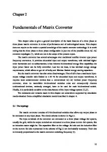
Fig. 1 shows a basic model of the commutation method with AC switches. The commutation has to simultaneously avoid the short circuit of the power supply and the open circuit of the load. We consider a four step commutation from the voltage souse v1 to voltage souse v2 based on Fig. 1.
S1a
S1b
v2
S2b
S2a
Fig. 1. Commutation model. 㪦㪥 㪦㪝㪝 S1a
㪦㪥
II. HYBRID COMMUTATION METHOD
v1
S1b
S1b
S2a
S2a
S2b
S2b
Td (a) Voltage commutation, (v1>v2).
Td (b) Voltage commutation, (v1v2, then the commutation sequence of the voltage commutation is obtained as follows; Initial condition ON: S1a, S1b OFF: S2a, S2b Step 1 S2a ON Step 2 S1a OFF Step 4 S1b OFF Step 3 S2b ON The commutation failure which creates the short circuit is caused by the changing point of the voltage direction. It should be noted that voltage commutation failure causes not only a distortion of the input current, but also, in the worst case, destroys the switching device by the large input current.
㪦㪝㪝
㪦㪝㪝
S1a
S1b
S1b
S2a
S2a
S2b
S2b Td Td (c) Current commutation, (iload>0). (d) Current commutation, (iload0, then the commutation sequence of the current commutation is obtained as follows; Initial condition ON: S1a, S1b OFF: S2a, S2b Step 1 S1b OFF Step 2 S2a ON Step 3 S1a OFF Step 4 S2b ON The commutation failure, which makes the open circuit, is caused at around the zero crossing point of the
Current commutation
Fig. 3. Proposed commutation method.
load current. It should be noted that current commutation failure causes not only a vibration of the output voltage, but also, in the worst case, destroys the switching device by a large surge voltage. In particular, failure of the current commutation continually occurs, because the wrong load current due to the commutation failure cannot flow in the right direction. In addition, the current commutation requires a reverse hysteresis characteristic to that of the current polarity signal. C. Hybrid commutation method Fig. 3 shows the principle of the proposed hybrid commutation method. As previously discussed, the voltage commutation is in danger of failing at around a voltage difference of zero, and the current commutation is
764
Tmax* Gate pulse Tmid* command Tmin* Commutation time Load current
㪂
Tmax**
㪂 㪂
Tmin**
Commutation pattern generator
6
㪄 㬍
iu > 0 : 1 iu < 0 :-1
㬍
sign(iu)
Threshold current level
(a) Configuration of a matrix converter.
Kcomm
Commutation select
Voltage commutation : 1 Current commutation : -1
Commutation command
Fig. 5. Proposed commutation error compensation.
commutation methods can be considered, one that actively uses the voltage commutation, and one that actively uses the current commutation. However, the current preference of a hybrid commutation is better than the others for a decrease in commutation failure when the output frequency is lower than the input frequency, because the number of commutation method changes decreases. III. ERROR COMPENSATION METHOD BY COMMUTATION A. Voltage error by commutation Fig. 4(a) shows an equivalent circuit for one phase of the matrix converter. The symbols, vmax, vmid, and vmin in Fig. 4(a), indicate the maximum, medium, and minimum voltage of the power supply, respectively. Figs. 4(b) and (c) show the relation between the output voltage and gate pulses of the matrix converter. The output voltage error occurs as shown by the shadowed part in Figs. 4(b) and (c). In the case of voltage commutation in the dead-time period, which means that both IGBT mode switching devices are turned-off, the output voltage determines the direction of the load current. The pulse width using the voltage commutation of the matrix converter can be expressed by Eq. (1).
(b) Voltage error in the case of voltage commutation.
Tmax*
㪦㪥
Td
㪦㪝㪝
Gate pulse Tmid* command Tmin* S1a S1b Commutation S2a S2b pattern S3a S3b Output voltage (Iload>0) Output voltage (Iload0, y=-1 when x