Hindawi Publishing Corporation Shock and Vibration Volume 2014, Article ID 809173, 8 pages http://dx.doi.org/10.1155/2014/809173
Research Article Improving Delay-Margin of Noncollocated Vibration Control of Piezo-Actuated Flexible Beams via a Fractional-Order Controller Teerawat Sangpet,1 Suwat Kuntanapreeda,1 and Rüdiger Schmidt2 1
Department of Mechanical and Aerospace Engineering, King Mongkut’s University of Technology North Bangkok, Bangkok 10800, Thailand 2 Institute of General Mechanics, RWTH Aachen University, D-52056 Aachen, Germany Correspondence should be addressed to Suwat Kuntanapreeda;
[email protected] Received 27 February 2014; Accepted 19 March 2014; Published 31 March 2014 Academic Editor: Vadim V. Silberschmidt Copyright © 2014 Teerawat Sangpet et al. This is an open access article distributed under the Creative Commons Attribution License, which permits unrestricted use, distribution, and reproduction in any medium, provided the original work is properly cited. Noncollocated control of flexible structures results in nonminimum-phase systems because the separation between the actuator and the sensor creates an input-output delay. The delay can deteriorate stability of closed-loop systems. This paper presents a simple approach to improve the delay-margin of the noncollocated vibration control of piezo-actuated flexible beams using a fractionalorder controller. Results of real life experiments illustrate efficiency of the controller and show that the fractional-order controller has better stability robustness than the integer-order controller.
1. Introduction Flexible structures have attracted increasing attentions for many applications because of their weights and production costs. However, the flexibility leads to unwanted vibration problems. Thus, vibration control is usually needed. Over the past few decades, active vibration control has drawn more interest from researchers since it can effectively suppress the vibration [1, 2]. A large part of the active vibration control research has used piezoelectric materials for actuation and sensing. Advantages of using piezo-actuators/sensors include nanometer scale resolution, high stiffness, and fast response. Piezo-actuators have been proven to be useful in suppressing structural vibration [3, 4]. Stabilization of flexible structures can be easily done by collocating the sensors and the actuators. However, the collocated control configuration is not always feasible in practice and its performance is not always satisfactory. Thus, noncollocated control has been investigated [5, 6]. However, noncollocated control results in a nonminimumphase closed-loop system because the separation between the actuator and the sensor creates an input-output delay, which can deteriorate stability of the closed-loop system.
Fractional calculus is a 300-year-old mathematical topic [7, 8]. However, its practical applications have just recently been explored. Recently, fractional-order control has been attracting interest. It has been illustrated that fractionalorder controllers yield superior performance to integer-order controllers [9, 10]. This paper presents a simple approach to improve the delay-margin of the noncollocated vibration control of piezoactuated flexible beams using a fractional-order proportional-integral-derivative (PID) controller. The rest of the paper is organized as follows. Section 2 provides some preliminaries. Section 3 describes the piezo-actuated flexible beam that is used as an experimental test bench. Section 4 presents a finite element model of the experimental beam. The proposed controller design is given in Section 5. Experimental results are presented in Section 6. The last section concludes the paper.
2. Preliminaries 2.1. Fractional-Order Calculus. The frequently used definitions of fractional-order derivatives are Riemann-Liouville
2
Shock and Vibration
definition, Gr¨unwald-Letnikov definition, and Caputo definition. The Riemann-Liouville definition is given as 𝐷𝑞 𝑓 (𝑡) =
𝑡 𝑓 (𝜏) 𝑑𝑚 1 [ 𝑑𝜏] , ∫ 𝑚 𝑑𝑡 Γ (𝑚 − 𝑞) 0 (𝑡 − 𝜏)𝑞−𝑚+1
1
1 𝑘 𝑞 𝐷 𝑓 (𝑡)𝑡=𝑘ℎ = lim 𝑞 ∑ (−1)𝑗 ( ) 𝑓 (𝑘ℎ − 𝑗ℎ) , 𝑗 ℎ→0ℎ
3
4
n−1
n
(1) Piezo-actuator
where 𝑞 is the fractional order, 𝑚 is the integer that 𝑚−1 < 𝑞 ≤ 𝑚, and Γ is the Gamma function. The Gr¨unwald-Lentnikov definition can be written as 𝑞
2
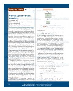
Figure 1: Finite element model of a piezo-actuated beam.
(2)
𝑗=0
2.2. Piezo-Actuator Equation. The equation relating the applied voltage and the axial strain produced by a piezoactuator is given as [11, 12]
where 𝑞 is the fractional order and 𝑞 (𝑞 − 1) (𝑞 − 2) ⋅ ⋅ ⋅ (𝑞 − 𝑗 + 1) 𝑞 ( )= 𝑗 𝑗!
(3)
is the usual notation for the binomial coefficients. The Caputo definition is described by 𝐷𝑞 𝑓 (𝑡) =
𝑡 𝑓(𝑚) (𝜏) 1 𝑑𝜏, ∫ Γ (𝑚 − 𝑞) 0 (𝑡 − 𝜏)𝑞−𝑚+1
(4)
𝜀𝑥𝑥 = 𝑑31
𝑚−1
(5)
𝑘=0
where 𝑚 is the integer that 𝑚 − 1 < 𝑞 ≤ 𝑚 and 𝐹(𝑠) = 𝐿{𝑓(𝑡)}. If all the initial conditions are zero, the Laplace transform of the fractional derivative becomes very simple as 𝐿 {𝐷𝑞 𝑓 (𝑡)} = 𝑠𝑞 𝐹 (𝑠) .
(6)
The transfer function of fractional 𝑞-order integrator and the fractional 𝑝-order derivative, respectively, is 1 𝐺 (𝑠) = 𝑞 , 𝑠
𝑝
𝐺 (𝑠) = 𝑠 .
(7)
The transfer function of the fractional-order proportionalintegral-derivative (PID) controller can be expressed as 𝐶 (𝑠) = 𝑘𝑝 + 𝑘𝑖
1 + 𝑘𝑑 𝑠𝑝 , 𝑠𝑞
𝑉 , 𝑡𝑝
(10)
𝜎𝑥𝑥 𝑧𝑑𝐴 = 𝐸𝑝 𝑑31 𝑏𝑧𝑉,
(11)
𝜎𝑥𝑥 = 𝐸𝑝 𝑑31 𝑀𝑎 = ∫
𝑡𝑏 /2+𝑡𝑝
𝑡𝑏 /2
where 𝑡𝑏 is the thickness of the beam, 𝐸𝑝 is Young’s modulus of the piezoelectric material, and 𝑧 = (𝑡𝑏 + 𝑡𝑝 )/2. 2.3. Finite Element Equation. Consider a simple cantilever beam with a piezo-actuator bonded on the surface as shown in Figure 1. It is assumed that the beam is divided into 𝑛 elements. Each element has two nodes and each node has two degrees of freedom: transverse direction (𝑤1 , 𝑤2 ) and slope (𝜃1 , 𝜃2 ). The transverse displacement at any 𝑥 position on the element can be expressed as [11, 13] [𝑤 (𝑥)] = [Φ]𝑇 [𝑞] ,
(12)
where [𝑞]𝑇 = [𝑤1 𝜃1 𝑤2 𝜃2 ] is the nodal displacement vector and [Φ]𝑇 = [𝜙1 𝜙2 𝜙3 𝜙4 ] is the mode shape vector function. By using the Lagrangian method, the differential equation of motion to be solved can be expressed as [14, 15] [𝑀] {𝑞}̈ + [𝐶] {𝑞}̇ + [𝐾] {𝑞} = {𝐹} ,
(8)
where 𝑘𝑝 , 𝑘𝑖 , 𝑘𝑑 , 𝑞, and 𝑝 are the controller parameters. It is worth noting that the fractional-order controller has two extra degrees of freedom compared to the conventional integer-order PID controller. This provides more freedom to better adjust the performance of the closed-loop systems.
(9)
where 𝑑31 is the dielectric constant of the piezoelectric material, 𝑉 is the applied voltage, and 𝑡𝑝 is the thickness of the piezoelectric material. When the piezo-actuator is bonded on the surface of a beam, the normal stress and the bending moment on the beam produced by the actuator are
where 𝑞 is the fractional order, 𝑚 is the integer that 𝑚 − 1 < 𝑞 ≤ 𝑚, and Γ is the Gamma function. These three definitions are equivalent to a wide class of functions [1, 2]. The most general expression of the Laplace transform of the fractional-order derivative is given as 𝐿 {𝐷𝑞 𝑓 (𝑡)} = 𝑠𝑞 𝐹 (𝑠) − ∑ 𝑠𝑘 𝐷𝑞−𝑘−1 𝑓 (0) ,
𝑉 , 𝑡𝑝
(13)
𝐿
where [𝑀] = 𝜌𝐴 ∫0 Φ𝑇 Φ𝑑𝑥 is the mass matrix, [𝐾] = 𝐿
EI ∫0 Φ𝑇 Φ 𝑑𝑥 is the stiffness matrix, [𝐶] is the damping matrix, and {𝐹} is the force matrix. For Raleigh proportional damping, 𝐶 = 𝛼𝑀 + 𝛽𝐾, where 𝛼, 𝛽 are the damping constants. The force matrix {𝐹} for the element
Shock and Vibration
3 Beam
y(t)
Laser displacement sensor
Interface board
u(t)
Piezoelectric actuator Power amplifier
Computer
(a)
(b)
Figure 2: Experimental system: (a) schematic, (b) photograph.
Table 1: Beam’s dimensions and properties. Dimensions/properties Young’s modulus Density Poisson ratio Length Width Thickness
Symbol 𝐸𝑏 𝜌𝑏 ] 𝐿 𝑏𝑏 𝑡𝑏
Value 70 2700 0.35 335 15 0.8
Table 2: Piezoelectric material’s dimensions and properties. Unit GPa kg/m3 — mm mm mm
Dimensions/properties Young’s modulus Density Length Width Thickness Strain coefficient
Symbol 𝐸𝑝 𝜌𝑝 𝑙𝑝 𝑏𝑝 𝑡𝑝 𝑑33 𝑑31
Value 66.67 7800 50 15 0.5 374𝑒−12 −171𝑒−12
Unit GPa kg/m3 mm mm mm m/V m/V
𝑇
without the piezo-actuator is {𝐹} = [0 0 0 0] and for the element bonded with the piezo-actuator is {𝐹} = 𝑇 [0 𝐸𝑝 𝑑31 𝑏𝑧 0 −𝐸𝑝 𝑑31 𝑏𝑧] 𝑉, which is directly derived from (11).
ratio is about 0.0097. The magnitude and duration of the pulse input are 1 V and 16 msec, respectively.
4. Finite Element Model 3. Experimental System A schematic and a photograph of the experimental system used in this paper are shown in Figure 2. The system consists of a flexible cantilever beam, a piezoelectric actuator, a highvoltage power amplifier, a laser displacement sensor, a 12-bit A/D and D/A interface board, and a PC. The beam is made of aluminum. The dimensions and properties of the beam are summarized in Table 1. The actuator is lead-zirconate-titanate (also known as PZT). It is bonded on the beam at the distance 𝑥 = 10 mm from the clamped point. The dimensions and properties of the actuator are summarized in Table 2. The sensor comprises a sensor head and a sensor amplifier. The sensor head makes use of a red laser semiconductor with a wavelength of 655 nm and an output power of 220 𝜇W. The measurement range is ±5 mm. The maximum sampling frequency is 3 kHz, but in our experiments, a default setting of 1 kHz was used. The sensor amplifier outputs an analog signal with a range of ±5 V. The sensor measures the tip displacement of the beam. The displacement signal is fed back to the PC through the interface board. The control signal from the computer is converted to an analogue signal by the interface board and is transmitted to the high-voltage power amplifier. The gain of the amplifier is 150. Figure 3 displays the pulse response and the frequency response function of the beam and shows that the first two natural frequencies of the beam are 41.6952 rad/s and 235.1796 rad/s and the damping
A finite element (FE) model of the experimental piezoactuated beam was developed for being used in the control design process. For simplicity, 𝑛 = 11 was chosen. The pulse response and the frequency response function obtained from the developed FE model are shown in Figure 4. The responses agree with those of the experimental system.
5. Control Design The control objective is to drive the tip of the beam to a desired position within 3 seconds. The proposed fractionalorder PID controller can be designed using the following steps. Step 1. Design a conventional integer-order PID controller based on an approximated lower-order transfer function of the beam. Here, the transfer function containing only the first natural frequency was employed. The transfer function is expressed as 𝐺 (𝑠) =
2 𝑘𝜔𝑛,1
2 𝑠2 + 2𝜁𝜔𝑛,1 𝑠 + 𝜔𝑛,1
,
(14)
where 𝜔𝑛,1 , 𝜁, and 𝑘 are the natural frequency, damping ratio, and system gain, respectively. The values found in Section 3
4
Shock and Vibration −20
0.4
−40
0.2 Magnitude (dB)
Tip position (mm)
0.3
0.1 0 −0.1 −0.2
−60 −80 −100
−0.3 −0.4 0
0.5
1
1.5
2 2.5 Time (s)
3
3.5
−120
4
101
102 Frequency (rad/s)
(a)
(b)
0.4
−30
0.3
−40
0.2
Magnitude (dB)
Tip position (mm)
Figure 3: Experimental system’s responses: (a) pulse response, (b) frequency response function.
0.1 0 −0.1 −0.2
−60 −70 −80
−0.3 −0.4
−50
−90 0
0.5
1
1.5
2 2.5 Time (s)
3
3.5
4
101
102 Frequency (rad/s)
(a)
(b)
Figure 4: System’s responses based on FE model: (a) pulse response, (b) frequency response function.
were used; that is, 𝜔𝑛,1 = 41.6952 rad/sec, 𝜁 = 0.0097, and 𝑘 = 0.64 mm/V. The transfer function of the controller is given by 1 𝐶 (𝑠) = 𝑘𝑝 + 𝑘𝑖 + 𝑘𝑑 𝑠, 𝑠
(15)
where 𝑘𝑝 , 𝑘𝑖 , and 𝑘𝑑 are the integer-order controller parameters. A root locus technique was used to determine the parameters. Step 2. Tune the integer-order controller parameters from Step 1 with a FE model of the beam. Here, the FE model developed in Section 4 was employed. The parameters of the controller were found to be 𝑘𝑝 = 1300, 𝑘𝑖 = 3100, and 𝑘𝑑 = 70. A step response of the control system based on the FE model is shown in Figure 5. The result shows that the control response meets the objective. The Bode characteristic of the open-loop transfer function is shown in Figure 6. The delay-margin is 13.9 msec.
Step 3. Replace the integrator of the tuned integer-order controller by a fractional-order integrator. The transfer function of the controller becomes 1 (16) 𝐶 (𝑠) = 𝑘𝑝 + 𝑘𝑖 𝑞 + 𝑘𝑑 𝑠, 𝑠 where 𝑞 is the fractional order. Here, 𝑞 = 0.85 was chosen. Step 4. Tune the parameters of the fractional-order controller from Step 3 with the FE model. Similar to Step 2, the parameters were found to be 𝑘𝑝 = 600, 𝑘𝑖 = 3100, and 𝑘𝑑 = 40. A step response of the fractional-order control system based on the FE model is shown in Figure 7. The result shows that the control response meets the objective with less initial oscillation compared to those of the integer-order controller. The Bode characteristic of the open-loop system is shown in Figure 8. The delay-margin was increased to 20.8 msec.
6. Experimental Results The integer-order controller (15) and the fractional-order controller (16) were implemented on the experimental beam
5
1.2
3
1
2.5
0.8
2 Control signal (V)
Tip position (mm)
Shock and Vibration
0.6 0.4 0.2
1.5 1 0.5 0
0 −0.2
−0.5
0
0.5
1
1.5
2 2.5 Time (s)
3
3.5
−1
4
0
0.5
1
1.5
(a)
2 2.5 Time (s)
3
3.5
4
(b)
50
200
Phase (deg)
Magnitude (dB)
Figure 5: Step response of the closed-loop FE model using the integer PID controller: (a) tip position, (b) control signal.
0 −50 10−1
100
101 Frequency (rad/s)
102
0 −200 −400 10−1
103
100
101 Frequency (rad/s)
(a)
102
103
(b)
1.2
3
1
2.5
0.8
Control signal (V)
Tip position (mm)
Figure 6: Bode characteristic of the open-loop transfer function based on the integer PID controller and the FE model: (a) magnitude, (b) phase.
0.6 0.4 0.2
1.5 1 0.5
0 −0.2
2
0
0.5
1
1.5
2 2.5 Time (s)
3
3.5
0
4
0
0.5
1
(a)
1.5
2 2.5 Time (s)
3
3.5
4
(b)
50
Phase (deg)
Magnitude (dB)
Figure 7: Step response of the closed-loop FE model using the fractional PID controller: (a) tip position, (b) control signal.
0 −50 10−1
100
101 Frequency (rad/s) (a)
102
103
200 0 −200 −400 10−1
100
101 Frequency (rad/s)
102
103
(b)
Figure 8: Bode characteristic of the open-loop transfer function based on the fractional PID controller and the FE model: (a) magnitude, (b) phase.
6
Shock and Vibration 1.4
3
1.2
2.5 Control signal (V)
Tip position (mm)
2 1 0.8 0.6 0.4 0.2 0
1.5 1 0.5 0 −0.5 −1
0
0.5
1
1.5
2 2.5 Time (s)
3
3.5
−1.5
4
0
0.5
1
1.5
(a)
2 2.5 Time (s)
3
3.5
4
(b)
1.4
3
1.2
2
1
Control signal (V)
Tip position (mm)
Figure 9: Step response of the closed-loop experimental system using the integer-order controller: (a) tip position, (b) control signal.
0.8 0.6 0.4
0 −1 −2
0.2 0
1
0
0.5
1
1.5
2 2.5 Time (s)
3
3.5
4
−3
0
0.5
1
(a)
1.5
2 2.5 Time (s)
3
3.5
4
(b)
Figure 10: Step response of the closed-loop experimental system with the added mass using the integer-order controller: (a) tip position, (b) control signal.
for comparison. The parameters of the controllers used in the experiments were obtained in the previous section and are summarized in Table 3. The controllers were implemented digitally on the PC. The control laws were written in 𝐶. The control sampling period was 1 msec for all experiments. The control response of the integer-order controller is shown in Figure 9, which shows satisfactory step response. Note that the oscillatory behavior in the experiment is greater than that in the FE model. This is due to the effect of the measurement noise and the uncertainties of the system’s parameters. After that, we added a 1.5-gram mass to the tip of the beam to examine the stability robustness of the controller. We found that the control system is unstable as shown in Figure 10. This is due to the delay (the effect of the noncollocated configuration). This implies that the closed-loop system does not have sufficient delay-margin. Now, the fractional-order controller is evaluated. The continued fraction expansion (CFE) of the Al-Alaoui operator [16] is used to discretize the controller. The control
Table 3: Parameters for the controllers. Integer-order controller 𝑘𝑝 = 1300 𝑘𝑖 = 3100 𝑘𝑑 = 70
Fractional-order controller 𝑘𝑝 = 600 𝑘𝑖 = 3100 𝑘𝑑 = 40 𝑞 = 0.85
response of the fractional-order controller is shown in Figure 11, which provides the same satisfactory response compared to those of the integer-order controller. Moreover, there is no marked difference compared to the FE result. This implies that the fractional-order controller is more robust to the noise and the uncertainties than the integer-order counterpart. Finally, we evaluated the stability robustness of the fractional-order controller by adding the 1.5-gram mass to the tip of the beam (in the same way that we did with the integer-order case). In this case, the control response is stable,
7
1.4
3
1.2
2.5
1
Control signal (V)
Tip position (mm)
Shock and Vibration
0.8 0.6 0.4
1.5 1 0.5
0.2 0
2
0
0.5
1
1.5
2 2.5 Time (s)
3
3.5
0
4
0
0.5
1
1.5
(a)
2 2.5 Time (s)
3
3.5
4
(b)
1.4
3
1.2
2.5
1
Control signal (V)
Tip position (mm)
Figure 11: Step response of the closed-loop experimental system with the fractional-order controller: (a) tip position, (b) control signal.
0.8 0.6 0.4
1.5 1 0.5
0.2 0
2
0
0.5
1
1.5
2 2.5 Time (s)
3
3.5
4
0
0
0.5
1
(a)
1.5
2 2.5 Time (s)
3
3.5
4
(b)
Figure 12: Step response of the closed-loop experimental system with the added mass using the fractional-order controller: (a) tip position, (b) control signal.
as shown in Figure 12. This is due to the larger delay-margin provided by the fractional-order controller.
7. Conclusions This paper presented the position control of a piezoactuated flexible beam using a fractional-order PID controller. The control employed a noncollocated configuration, which always produces input-output delay. The fractionalorder controller was designed to increase delay-margin of the closed-loop system. Experimental results show that the fractional-order controller provides better stability robustness than the integer-order counterpart.
Conflict of Interests The authors declare that there is no conflict of interests regarding the publication of this paper.
Acknowledgment This work was supported by the Royal Golden Jubilee Ph.D. Program of the Thailand Research Fund.
References [1] C. C. Fuller, Active Control of Vibration, Academic Press, 1996. [2] A. Preumont, Vibration Control of Active Structures, Kluwer Academic Publishers, 2004. [3] S. V. Gosavi and A. G. Kelkar, “Modelling, identification, and passivity-based robust control of piezo-actuated flexible beam,” Journal of Vibration and Acoustics, vol. 126, no. 2, pp. 260–271, 2004. [4] Z. Zhang, Y. Chen, H. Li, and H. Hua, “Simulation and experimental study on vibration and sound radiation control with piezoelectric actuators,” Shock and Vibration, vol. 18, no. 1-2, pp. 343–354, 2011. [5] Z. Qiu, J. Han, X. Zhang, Y. Wang, and Z. Wu, “Active vibration control of a flexible beam using a non-collocated acceleration
8
[6]
[7] [8]
[9]
[10]
[11]
[12]
[13]
[14]
[15] [16]
Shock and Vibration sensor and piezoelectric patch actuator,” Journal of Sound and Vibration, vol. 326, no. 3-5, pp. 438–455, 2009. C. Spier, J. C. Bruch, J. M. Sloss, I. S. Sadek, and S. Adali, “Effect of vibration control on the frequencies of a cantilever beam with non-collocated piezo sensor and actuator,” IET Control Theory and Applications, vol. 5, no. 15, pp. 1740–1747, 2011. I. Podlubny, Fractional Differential Equations, Academic Press, 1999. D. Cafagna, “Fractional calculus: a mathematical tool from the past for present engineers,” IEEE Industrial Electronics Magazine, vol. 1, no. 2, pp. 35–40, 2007. C. A. Monje, B. M. Vinagre, V. Feliu, and Y. Chen, “Tuning and auto-tuning of fractional order controllers for industry applications,” Control Engineering Practice, vol. 16, no. 7, pp. 798–812, 2008. T. Sangpet and S. Kuntanapreeda, “Force control of an electrohydraulic actuator using a fractional order controller,” Asian Journal of Control, vol. 15, no. 3, pp. 764–772, 2013. B. Bandyopadhyay, T. C. Manjunath, and M. Umapathy, Modeling, Control and Implementation of Smart Structures: A FEMState Space Approach, Spinger, Berlin, Germany, 2007. Z. Qiu, X. Zhang, and C. Ye, “Vibration suppression of a flexible piezoelectric beam using BP neural network controller,” Acta Mechanica Solida Sinica, vol. 25, no. 4, pp. 417–428, 2012. V. Y. Perel and A. N. Palazotto, “Finite element formulation for dynamics of delaminated composite beams with piezoelectric actuators,” International Journal of Solids and Structures, vol. 39, no. 17, pp. 4457–4483, 2002. S. Y. Wang, “A finite element model for the static and dynamic analysis of a piezoelectric bimorph,” International Journal of Solids and Structures, vol. 41, no. 15, pp. 4075–4096, 2004. D. L. Logan, A First Course in the Finite Element Method, Wadsworth Group, 2002. B. M. Vinagre, I. Podlubny, A. Hernandez, and V. Feliu, “Some approximations of fractional order operators used in control theory and applications,” Fractional Calculus and Applied Analysis, vol. 3, pp. 231–248, 2000.
International Journal of
Rotating Machinery
Engineering Journal of
Hindawi Publishing Corporation http://www.hindawi.com
Volume 2014
The Scientific World Journal Hindawi Publishing Corporation http://www.hindawi.com
Volume 2014
International Journal of
Distributed Sensor Networks
Journal of
Sensors Hindawi Publishing Corporation http://www.hindawi.com
Volume 2014
Hindawi Publishing Corporation http://www.hindawi.com
Volume 2014
Hindawi Publishing Corporation http://www.hindawi.com
Volume 2014
Journal of
Control Science and Engineering
Advances in
Civil Engineering Hindawi Publishing Corporation http://www.hindawi.com
Hindawi Publishing Corporation http://www.hindawi.com
Volume 2014
Volume 2014
Submit your manuscripts at http://www.hindawi.com Journal of
Journal of
Electrical and Computer Engineering
Robotics Hindawi Publishing Corporation http://www.hindawi.com
Hindawi Publishing Corporation http://www.hindawi.com
Volume 2014
Volume 2014
VLSI Design Advances in OptoElectronics
International Journal of
Navigation and Observation Hindawi Publishing Corporation http://www.hindawi.com
Volume 2014
Hindawi Publishing Corporation http://www.hindawi.com
Hindawi Publishing Corporation http://www.hindawi.com
Chemical Engineering Hindawi Publishing Corporation http://www.hindawi.com
Volume 2014
Volume 2014
Active and Passive Electronic Components
Antennas and Propagation Hindawi Publishing Corporation http://www.hindawi.com
Aerospace Engineering
Hindawi Publishing Corporation http://www.hindawi.com
Volume 2014
Hindawi Publishing Corporation http://www.hindawi.com
Volume 2014
Volume 2014
International Journal of
International Journal of
International Journal of
Modelling & Simulation in Engineering
Volume 2014
Hindawi Publishing Corporation http://www.hindawi.com
Volume 2014
Shock and Vibration Hindawi Publishing Corporation http://www.hindawi.com
Volume 2014
Advances in
Acoustics and Vibration Hindawi Publishing Corporation http://www.hindawi.com
Volume 2014