Improving power quality with coordinated voltage control in networks with dispersed generation Tomaž Pfajfar, Igor Papič
Benoit Bletterie, Helfried Brunner
Faculty of Electrical Engineering University of Ljubljana Ljubljana, Slovenia
[email protected]
arsenal research Vienna, Austria
[email protected]
Abstract—Rapidly increasing share of distributed generation (DG) in distribution networks introduced the need for active distribution network operation. As current distribution networks were not designed to integrate the power generation, the DG introduced many technical challenges in sense of power quality, network planning, protection schemes, voltage stability…. This paper presents the advantages of active approach in distribution network operation. The paper focuses on a voltage quality problem and introduces the coordinated voltage control technique to increase the share of DG in distribution networks and at the same time supply the customers with the required voltage quality. Keywords-distributed generation; active distribution network operation; coordinated voltage control
I.
INTRODUCTION
International community, faced with the environmental challenge and increasing energy demand world wide, realized that the future energy policy should rely more on “clean” energy supply i.e. renewable energy sources. As renewable energy sources are usually widespread in the low and medium voltage networks, we are talking about distributed or dispersed generation (DG). Power systems were designed for energy to flow from transmission to distribution network where energy is supplied to the customers. However, with the adoption of DG the situation in the network could change and energy flow could become bidirectional. Due to passive operation of distribution networks, the present distribution networks are not capable to integrate high share of DG. Most of the distribution network operators (DNOs) still use the so called "fit and
forget" philosophy to integrate DG into existing distribution networks. That means once the DG unit is connected to the network the DNO does not care about it. This principle allows only limited share of the DG to be connected. To increase the share of DG in the distribution networks active distribution network operation is necessary. That means a contribution of DG to the network operation aspects is needed. An increasing share of DG brings many technical challenges in sense of power quality, protection schemes, system stability…. The paper presents the advantages of the active approach in distribution network operation with high share of DG. Distribution networks with high DG penetration require active approach in sense of operation, control, communication and protection. Active approach includes measurements and control of network variables e.g. voltages in real time, using management of various network devices. The paper focuses on voltage quality problems which is a very common problem for DNOs in distribution networks with DG [1]. Coordinated voltage control is introduced as an active approach of distribution network operation. The control concept was developed within the Austrian project DG DemoNet-Concept [2]. The results in the paper are based on a simulation model of a real medium voltage (MV) distribution network in Austria. II.
ACTIVE NETWORK
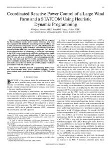
The aim of active networks is to increase the share of DG in existing distribution networks [3] and keep the system stable and reliable at the same time. An example of an active network is presented in Fig. 1. Active network can be defined as
• to choose representative parts of distribution networks in Austria for practical realization of demonstration networks with high DG penetration, • to analyze the possibilities for implementing different model systems (step model of DG integration) and plan the technical, organizational and economical realization. Within the project a simulation study was used to find and compare different solutions for voltage control. Different control techniques were examined to improve the performance of the distribution network and allow more DG to be connected. Within the project also economical evaluation of each voltage control solution will be carried out. Coordinated voltage control is presented in this paper as the most complex approach that could be used as part of the active network management. III. Figure 1. Active network example.
network with arbitrary power flow along the network feeders, where voltages are measured or estimated, and controlled in real time, using management of the various devices (DG units, FACTS devices, on-load tap changer (OLTC) transformers…). The central control system represents an intelligent system able to decide and operate the distribution network, taking into account the present network conditions. To determine the network conditions state estimation or real time measurements are required. However, to operate the distribution system safely, the central control system would need backup scenarios in case of failure in the control or communication systems. Parts of active network management are: • real time measurements or distribution network state estimation, • communication technology, • intelligent central control system, • local DG control systems, • demand side management, • energy storage. A. The Project DG DemoNet - Concept The Austrian project DG DemoNet - Concept [2, 4] presents new strategies in the field of DG where currently passive distribution networks become active networks, able to accommodate a significant penetration from DG. Active network management introduces many new challenges in network planning and control, supervision, information and communication technology. However, so far mainly theoretical part of the problem was addressed in the research sphere. The aim of the DG DemoNet - Concept project is to transfer the theoretical knowledge into a practical realization of a demonstration network where active network management is implemented with the least investment costs. The main goals of the DG DemoNet - Concept project are:
COORDINATED VOLTAGE CONTROL
The coordinated voltage control includes the voltage control with the OLTC transformer and local voltage control with DG units and other controllable network devices. The use of local voltage control allows solving the voltage conflicts that can not be solved with the network devices e.g. OLTC transformers. The control is based on measurements from critical points in the network. Critical points are nodes where either the maximum or the minimum voltage may occur under the various network load and generation conditions. The critical points in the network can be determined with an offline study, DNOs experience…. The communication lines are required to transmit measured voltages from remote points. Depending on the chosen communication technology, a varying delay on these lines has to be expected. The flow chart of coordinated voltage control is shown in Fig. 2. The algorithm is designed to optimize the DG units operation to avoid unnecessary power curtailments and additional reactive power flows. However, if the voltage problem can not be solved with the algorithm, the problematic DG unit is disconnected from the network by the current approach via under or over voltage protection. The presented algorithm does not consider any fault conditions and deals only with the network steady state conditions. A hierarchical concept is introduced between different network devices. In the first place the OLTC transformer is used to solve the problematic voltage conditions following the local control with controllable DG units and other controllable devices. The central control system determines the minimum and maximum voltage in the network based on the incoming measurement data. According to minimum and maximum voltage the OLTC transformer is set. In case the voltage problem can not be solved with OLTC transformer (e.g. the tap change would cause voltage violations somewhere in the network - voltage conflict), local voltage control is activated.
network studies, according to current conditions in the network (possible voltage conflicts) and to the ranking table, the central control system sends the voltage set point information to the chosen controllable device (DG unit, FACTS…). IV.
SIMULATION STUDY
The simulation study of the coordinated voltage control technique in distribution network with high DG share was performed in the DIgSILENT PowerFactory simulation software. The coordinated voltage control was used on a real MV distribution network model that was provided by one DNO participating in the DG DemoNet project. The MV distribution network model is presented in Fig. 3. The network comprises of approximately 200 nodes and represents maximum demand of about 9 MW. The distribution network is connected to the transmission network over a 30/110 kV, 20 MVA OLTC transformer. The Transformer has a on load tap changer on the high voltage (HV, 110 kV) side with ±12 voltage steps each with 1,833 kV. The transformer is supplying two main branches radial operated. The network short circuit power is estimated to 3500 MVA.
Figure 2. Flow chart algorithm of coordinated voltage control.
A. Local voltage control Local voltage control includes the control of controllable DG units, FACTS devices, capacitor banks, energy storage etc. The local voltage control is based on the active (P) and reactive (Q) power management. Due to high R/X ratio in distribution networks, the active power has a distinctive influence to the voltage profile. As DG usually cause the voltage rise, the generation curtailment presents an instrument to keep the voltage inside required limits. However, the power curtailment should not be the first step in voltage control management. Voltage control with reactive power should be considered before reducing the generation. For DG the DNOs usually require to operate with unity power factor. With the active approach the reactive power exchange should be defined according to the current conditions in the network. To avoid unnecessary reactive power flow the reactive power management should be active only when necessary therefore the reactive power management with the fixed voltage set point should be avoided. In case the voltage is outside required limits the voltage control with reactive power based on variable voltage set point should be activated to prevent voltage violations. The variable voltage set point is determined according to current conditions in the network. The voltage set point can be determined with the central control system. B. Ranking and Decision System When local voltage control is activated the controllable DG units or other controllable devices are grouped according to their impact on the voltage level at each monitored point in the network. The central control system includes the table where controllable devices are ranked according to their influence on the voltage level. The ranking system can be based on off line
Due to design and operational restraints of the low voltage (LV) networks, the available voltage bandwidth that can be explored with the active network management in the MV network is +3/-6 % of the rated voltage (30 kV). This bandwidth has been used in the simulations. If there would be no such restriction, wider bandwidth (±10 % according to [6]) could be used for voltage control. Based on the simulation study eight points in the network are chosen for observation (Fig. 3). These are critical voltage
Figure 3. Simulation model of a real distribution network.
points in the network, where either the maximum or the minimum voltage may occur under the various network load and generation conditions. Additionally also voltage at the substation is monitored. Loads and DG units are modeled based on the profiles from real measurement data. Additional DG units are connected to the MV network for simulation purpose to increase the share of DG. New DG units are connected on various locations where possible and reasonable to exploit nature potentials. Four DG units (DG4, DG5, DG10 and DG12) are available for local voltage control with active and reactive power management. No other devices are involved in the local voltage control. The controllable DG units are ranked according to Table I. There are no controllable devices near the critical nodes Vg and Vh therefore no local voltage control is available there. The ranking concept can be explained on the following example. If the voltage at node Va is the node with the maximum voltage in the network, and exceed the upper voltage limit, and OLTC transformer is insufficient to solve the situation, first DG4 should try to reduce the voltage with the reactive power management. When DG4 reaches the limit of reactive power, the reactive power management with DG5 is activated. If both active DG units run on its limits with reactive power, DG10 is next to be activated. If the voltage control with reactive power management is not effective enough the generation curtailment is used to reduce the voltage. Again the same ranking concept is used as in case of reactive power management. If the maximum voltage appears at any other location while the controllable DG units are operated according to node Va in Table I, the active controllable DG units remain controlling node Va until it is included in ranking concept of any other node. Three basic voltage conflicts can appear and two different set points for controllable DG units are defined. Basic voltage conflicts are presented in Fig. 4. If maximum and minimum TABLE I.
RANKING CONCEPT OF CONTROLLABLE DG UNITS.
Ranking of DG units
Monitored points Va
Vb
Vc
Vd
Ve
Vf
Vg
Vh
DG10
DG5
DG12
DG10
DG4
DG10
/
/
DG5
DG4
DG10
DG12
DG5
DG4
DG10
voltages exceed the limits or only minimum voltage is below the low voltage limit while maximum is close to the upper voltage limit, the controllable DG units should reduce the maximum voltage to a value where OLTC transformer is able to change the tap position (Uset=Uup_lim-Utap) without causing any overvoltage or undervoltage in the network. If maximum voltage exceeds the upper voltage limit and minimum voltage is close to the low voltage limit, the DG units in Table I should control the voltage to be below the upper voltage limit (Uset=Uup_lim). In case some controllable devices would be available to solve the undervoltage problem (e.g. controllable DG units near nodes Vg or Vh), before reducing the maximum voltage to enable tap change, they should try to increase the minimum voltage. V.
SIMULATION RESULTS
The integration capability of DG units determined by voltage level requirements depend on location and type of DG, correlation between power production and load demand, network parameters and configuration etc. The conservative planning concept of "minimum demand - maximum production" and "maximum demand - minimum or zero production" presents a severe barrier for DG integration [5]. In the paper the planning principle is extended to consider stochastic nature of DG by using load and production profiles based on real measurements. This approach is not based on a single worst case but a series of possible network conditions. Simulation results are based on different network loading conditions (different DG penetration level, different days, seasons) and on different weather conditions. The results presented in the paper are based on a sunny winter workday and a sunny summer Sunday. The peak energy production from the DG units (sum of energy from all DG units) appears in the evening and during the night. During the maximum demand in the network the production from DG units is relatively small. A. Voltage conditions in the network Voltage conditions on winter workday in case of passive network operation are represented in Fig. 5. The DG share is 50 % (4.5 MW) of the maximum load demand in the network. Passive approach includes only automatic voltage control with HV/MV, OLTC transformer with a fixed bus-bar voltage
DG10
Figure 4. Basic voltage conflicts.
Figure 5. Voltage at monitored points in the network - winter workday, passive approach, 4,5 MW of DG.
(substation) as set point. A box plot for each monitored point in the network is shown in Fig. 5 where 25 %, 50 %, 75 %, minimum and maximum values are represented. The colored columns show whether the 10-minute voltage is between limits in 95 % of the day. The results show that the maximum voltage is at node Ve, where DG4 unit is connected. The maximum voltage achieved on workday in winter is around 5 % above the nominal voltage, which is outside the limits required by the DNO. With the passive approach the OLTC transformer does not perceive the voltage violations therefore the OLTC position stays unchanged and controls only the voltage in the transformer substation. Active approach is necessary to keep the voltage between the limits in case of high penetration from DG units. In the next case the coordinated voltage control is used to actively control the network voltages. The share of DG is increased to 9 MW and represents a 100 % of the maximum load demand. Therefore the installed power of the new DG units was increased. Voltage conditions on winter workday and summer Sunday are represented in Fig. 6 and Fig. 7. It can be seen that voltages are in both cases inside required limits. No power was
curtailed and only reactive power management of DG4 unit was activated to keep the voltage inside required limits. All other controllable DG units were operating undisturbed with unity power factor. Active and reactive power flow from DG4 unit for summer Sunday is represented in Fig. 8. The negative sign represents the power generation. Although the highest penetration from DG4 appears in time of low demand (during the night), the coordinated voltage control is able to ensure the required voltage quality to the customers. If the share of DG is increased to 150 % of the maximum demand (i.e. 13.5 MW) the power curtailment is activated to keep the voltage inside the limits. Only power from DG4 has to be curtailed to keep the voltage between the limits. The worst conditions appear at summer Sunday when small load demand and high generation is noticed. The voltage conditions in the network are represented in Fig. 9. It can be seen that in 95 % of the time the voltage is successfully kept between the limits and therefore suitable voltage quality is provided to the customers. The power flow and curtailed energy (Wcurt) of DG4 is represented in Fig. 10. 12.7 % of the energy available from DG4 is lost due to coordinated voltage control. The amount of
Figure 6. Voltage at monitored points in the network - winter workday, coordinated voltage control, 9 MW of DG.
Figure 8. Power flow from DG4 - summer Sunday.
Figure 7. Voltage at monitored points in the network - summer Sunday, coordinated voltage control, 9 MW of DG.
Figure 9. 5. Voltage Voltage at at monitored monitored points points in in the the network network -- summer winter workday, Figure Sunday. passive approach, 4,5 MW of DG.
production would match to the network demand, the losses could be reduced. VI.
Figure 10. Power flow from DG4 - summer Sunday.
lost energy on a summer Sunday is 3.6 MWh. Other controllable DG units were involved only with reactive power management and did not have any reduction in energy production. The curtailed energy is relatively small regarding to the total power exported from all DG units. The total amount of energy produced by DG units is around 200 MWh per day in case the installed DG power represents a 150 % of the maximum demand. Therefore only about 2 % of the energy is lost on this particular day. B.
Network losses Network losses depend on the share of the DG in the network and on network conditions. According to the current situation in the network, the network losses in case of 13.5 MW (150 % of the maximum demand) of installed DG increase five to six times to around 15 MWh. However, the presented scenario is almost worst case that can appear in the network where energy production basically does not match to load demand. The power flow through the HV/MV transformer on the summer Sunday is presented in Fig. 11. It can be seen that the power flow is reverse all day. During the time of high load demand the generation almost covers the demand therefore the power flow through the transformer is small. In case the energy
Existing distribution networks were not designed to integrate a high share of DG. Active network management is necessary to increase the share of DG. The paper deals with voltage quality problem which is the most common problem for DNOs when dealing with DG. Coordinated voltage control was introduced to actively control the network. The coordinated voltage control would allow more DG to be connected and at the same time supply the customers with the required voltage quality. However, the coordinated voltage control technique presents a complex structure where different devices (e.g. DG units, OLTC transformers…) are operated according to the current network situation. To develop such a complex structure relatively high investment cost are expected. Within the project DG DemoNet - Concept also economical evaluation of different solutions for voltage control will be performed. For practical implementation of coordinated voltage control reliable communication technology is necessary. To assure safe and stable operation of the distribution network also backup scenarios in case of failures should be discussed. The investment costs in the communication systems are directly connected to the system security and reliability where DNOs require high standards. However, the costs for active network management must not exceed the costs for conventional grid reinforcements therefore within DG DemoNet also different communication solutions will be considered and evaluated. Within the paper it was shown that the coordinated voltage control would allow the integration of large amount of DG. However, ongoing work will show the feasibility and practicability of different voltage control solutions. Further project steps will introduce the best solutions for active network management that can be implemented with the least investment costs. Finally, the economically and technically feasible solutions for active network operation will be implemented and validated for different Austrian grid segments. REFERENCES [1] [2] [3]
[4]
[5]
[6]
Figure 11. Power flow through the HV/MV transformer - summer Sunday.
DISCUSSION
C. R. Dugan, M. F. McGranaghan, S. Santoso, H. W. Beaty, “Electric Power System Quality,” McGraw-Hill, New York, 2002. arsenal research, “DG DemoNet - Concept,” project documentation. S. N. Liew, G. Strbac, “Maximising penetration of wind generation in existing distribution networks,” IEE Proc. Generation, Transmission and Distribution, vol. 149, no. 3, pp. 256-262, may 2002. H. Brunner, B. Bletterie, A. Lugmaier, T. Pfajfar “Strategien für die Spanungsregelung in Verteilnetzen mit einem hohen Anteil an dezentralen Stromeinspeisern,” 5th International Energy Conference Vienna (IEWT 2007), Vienna, Austria, Feb. 2007. S. Repo, H. Laaksonen, P. Jarventausta, “New Methods and Requirements for Planning of Medium Voltage Network due to Distributed Generation,” NORDAC 2004, Espoo, Finland. EN 50160, “Voltage characteristic od electricity suplied by public distribution networks,” standard, Nov. 1999.