If the damage of the hard- ware is not too bad we might distinguish three different scenarios. In the first ... ate repair action also can be a reconfiguration of the hardware or its ... omnidirectional drive of robots of our RoboCup Middle-Size team.
Improving robustness of mobile robots using model-based reasoning Michael Hofbaur1 and Johannes K¨ob1 and Gerald Steinbauer2 and Franz Wotawa2 Institute for Automation and Control, Graz University of Technology, Inffeldgasse 16c/II, A-8010 Graz, Austria Institute for Software Technology, Graz University of Technology, Inffeldgasse 16b/II, A8010 Graz, Austria This research has been funded in part by the Austrian Science Fund (FWF) under grant P17963-N04. Abstract. Retaining functionality of a mobile robot in the presence of faults is of particular interest in autonomous robotics. From our experiences in robotics we know that hardware is one of the weak points in mobile robots. In this paper we present the foundations of a system that automatically monitors the driving device of a mobile robot. In case of a detected fault, e.g., a broken motor, the system automatically re-configures the robot in order to still allow it to reach a certain position. The described system is based on a generalized model of the motion hardware. The novelty of the framework is that the same hardware model is used for diagnosis and re-configuration. Therefore, the high-level control like path-planner only have to change its behavior in case of a serious damage. In the paper we present the model and the foundations of the diagnosis and re-configuration system.
1 Introduction Retaining the functionality of a mobile robot even in the presence of faults in its hardware is of particular interest. This fact becomes even more important in the case of truly autonomous systems, which are carrying out tasks without or at least with limited possibility for interacting with a human operator. Hardware faults like broken or overheated motors, are well known phenomena in the robotics domain. These problems are not limited to research prototypes. Even in commercial or safety-critical applications the reliability of robotics hardware is limited and tends to fail frequently. See for example [1] for a qualitative and quantitative estimation about the reliability of robotics hardware which justifies these observations. In general a robot will not be able to successfully finish its task in the case of a fault in its hardware. If the robot should be able to deal with such situations automatically, the robot control system has to be enriched with the capability for reasoning about such faults. Furthermore, the control system should be able to adapt its behaviors in order to compensate for the faults. If the damage of the hardware is not too bad we might distinguish three different scenarios. In the first scenario, the robot is able to retain its full physical functionality. This means that the control system was able to detect and locate the fault in the hardware. Furthermore, the control system was able to repair the fault by taking an appropriate repair action like restarting the faulty hardware component. Moreover, an appropri-
ate repair action also can be a reconfiguration of the hardware or its low-level control software. This is only successful if the robot offers a certain level of redundancy. An example for this situation is the omnidirectional drive of robots of our RoboCup Middle-Size team Mostly Harmless[13]. This omnidirectional drive comprises four motors with omni-wheels in a cross arrangement. If one of the motors fails, the robot is able to retain its omni-directional motion capability by a reconfiguration of the low-level drive controller. The remaining three motors offers enough actuation for controlling all three DOF in the plane. In the second scenario the damage of the hardware can be not sufficiently compensated and therefore the functionality of the robot degrades. This means the robot control system is not able to take appropriate actions in order to retain the full functionality of the robot. But the robot is not yet doomed to fail in carrying out its task as long the robot control system is able to detect this scenario. Moreover, if the control system is able to reason about this degradation it can adapt its behavior in order to compensate the limited functionality. Therefore, the robot may still be able to finish its task. An example for such a situation is an omnidirectional robot with three omni-wheels. If one motor fails the drive can be reconfigured to an differential drive. In most cases a robot is still able to carry out its task with a different type of locomotion. But most likely without the same performance, e.g. longer duration of the task execution. Finally, if faults in the robots hardware occur and none of the two scenarios above fit, the robot lost its physically capabilities to carry out its task. But the knowledge about this fact is still valuable because the high level control may set the robot to a safe state and may informs an human operator. In this paper we present a generalized framework for improving the robustness of the motion of mobile robots. The framework is able to recognize and to handle the three scenarios outlined above. The framework comprises three parts. Which are extensions to the wellknown hybrid robot control architecture for mobile robots [10]. The first part is a generalized meta-model about the capabilities of the motion system. It models the behavior of the motion hardware in all of its possible nominal and faulty operational modes. The second part is a model-based diagnosis engine. The engine is able to detect and localize faults in the robots hardware by reason about the meta-model and current observations of the system. The last part is a model-based motion controller. Based on a concrete motion model this controller carries out a motion control by mapping immediate control signals provided from a path-planner to low-level commands for the actuators. The concrete motion model is an instantiation of the meta-model where an estimated operational mode of the hardware is used. One important issue is that the meta-model remains the same in all scenarios. It is created by an engineer concerning all motion con-
straints of the hardware. The fault-detection and the adaptation of the controller is autonomously carried out by the framework without interaction with an operator or engineer. We continue paper with a deeper description of the proposed framework in Section 2. In Section 3 we discuss the model-based diagnosis engine. In the next section, we show how the meta-model is created and used for motion control. Finally in Section 5 we present related research and draw some conclusions.
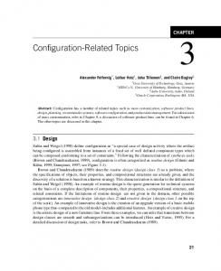
2 Framework In order to improve the robustness of mobile robots and to meet the above stated requirements we propose a generalized framework for fault-tolerant motion control. A picture of the framework is shown in Figure 1. The framework is a general pattern for the intelligent and robust control of a mobile robot. Within this paper, we discuss the framework for the improvement of the reliability of motion control. However, the framework can be easily adapted to other aspects of mobile robots like manipulators or even control software in general. Symbolic Diagnose
Deliberative Control
Diagnosis Engine
Path Planner/ Path Executor
Estimated Operational Mode
Movement Request
Meta Motion−Model
Immediate Control Signals
Specialization Motion Constrains
Model−Based Motion Controller
Concrete Motion−Model
Low−Level Control Signals
Movement Observations
Robot Drive
Figure 1. The generalized framework for fault-tolerant motion control.
The left three components in the figure form a classical hybrid robot control architecture. On top of the architecture a deliberative component performs longterm planning and reasoning on an abstract logic-based level. Desired actions like move to position A are committed to the path-planner. The path-planner tries to find a path to the desired position based on a model about the world and the kinematic capabilities of the robot. If a path is found, the path-executor moves the robot along this path. Usually, this is done by sampling the path and committing immediate control signals like velocity and acceleration in the global or local reference frame to a motion controller. The motion controller is responsible for converting these immediate control signals into appropriate control signal for the actuators like turning speeds of motors. In many applications a reactive obstacle avoidance behavior is also part of this control chain. In general the motion controller and sometimes even the pathplanner contain an engineered model about the kinematics of the
robot. Usually, this model represents the nominal behavior of the system. Therefore, in the presence of a fault in the robots hardware the motion controller or even the path-planner tends to fail to appropriately move the robot along a desired path. This happens because the implicit model of the robot kinematics does not adapt to the new situation. In order to improve the robustness of the motion control and to be able to handle faults in the robots hardware, we propose an enriched framework. The additional parts of this framework are: (1) a metamodel of the kinematics of the robot, (2) a model-based diagnosis engine and (3) a model-based motion controller. In contrast to an implicit engineered motion-model the metamodel is a generalized motion-model. It is built up by a combination of all motion constraints of the robot. The individual motion constraints are defined by the number, the arrangement and type of all the wheels of the robot. Therefore, it is possible to model all types of wheeled robots. See [12] for an introduction to kinematic constraints. In Section 4 we present an example for a simple meta-model. The advantage of this meta-model is that it contains the kinematic models for all possible operational modes of the robot. In this context we understand operational modes as the different situations with the presence of no or different combinations of faults in the hardware. It is obvious that the hardware shows different behaviors in the different operational modes. The advantage of the meta-model is that it has to be engineered only once and remains the same as long the robots hardware does not change. This meta-model is used by the model-based diagnosis engine to detect and identify faults in the hardware. For this purpose the metamodel is used to predict the behavior of the robot for all possible operational modes. It has to be noticed that there is exactly one nominal mode (no faults) and a number of abnormal modes (different faults). The number of the abnormal modes depends on the number of possible combinations of different faults. The diagnosis engine regularly compares the results of all predictions with the actual observations of the system. If there is a deviation between the prediction of the nominal behavior and the observed behavior, a fault has been detected. Possible observations are, e.g., the actual movement of the robot measured by odometry, the supply current or torque of a motor, optical flow in a camera image. By a tracking of all possible abnormal behaviors the most probable abnormal operational mode is estimated. This estimated mode also contains information about the exact root cause of the fault, e.g., which motor is broken. Modelbased diagnosis is introduced in more details in the next section. So far the framework is able to detect and identify faults. In order to react on such faults the framework has three possibilities. First, the framework creates a concrete instance of the meta-model. This concrete model mimics the behavior of the kinematic in the estimated operational mode. Such a concrete model is used by the model-based motion controller to provide an appropriate mapping of the immediate control signals to the low-level control signals of the actuators. The adaptation of this mapping to the concrete motion model can be carried out autonomously by the framework. Such an adaptation may cause an degradation of the functionality as noticed in the example in the introduction. Furthermore, the concrete motion-model is able to postulate additional motion constraints. Advanced path-planning algorithms [8, 2] are able to take advantage from such constraints in order to find an feasible path. But it is neither guaranteed that the model-based controller is able to find an appropriate mapping nor that the path-planner is able to find an executable path in the presence of additional motion constraints. However, this information are also valuable. The deliberative control can be informed that because
of the serious damage of the hardware the robot is unable to move in a desired way. This information may be used by the deliberative component to stop the robot and to inform an operator about the situation. The proposed framework is able to detect faults in the hardware and to react to these faults. Either the model-based motion controller and the path-planner adapt itself to the new situation or a dangerous situation can be recognized and appropriate action can be taken. In the next section we discuss model-based diagnosis in more details.
:ok(M ) ^ ok(M ) r
ok M ^ ok M (
r)
(
l
:ok(M ) ^ :ok(M )
l)
r
ok M (
r)
l
^ :ok(M ) l
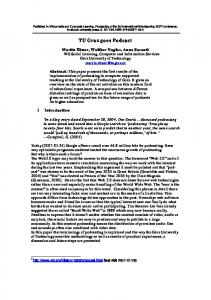
3 Diagnosis Diagnosis is the task of detecting and localizing faults. For example monitoring approaches or verification approaches implement fault detection. After fault detection the focus is on identifying the root cause, i.e., the diagnosis, of the faulty behavior. This task is referred as fault localization. Finally, someone is interested in changing the system in a way such that the systems behaves like expected. This final task is fault repair. In this section we focus on fault detection and fault localization. In particular we introduce the basic ideas of model-based diagnosis [11] and explain how these ideas apply for the diagnosis part of fault tolerant motion control. In model-based diagnosis the fault detection and localization part is based on a model of the systems. This model captures the intended behavior of the system and allows for computing predictions. When comparing these predictions with the observed behavior of the real system, we distinguish two situations. Either the predictions are consistent with the observations, or not. The latter case is obviously an indicator for the manifestation of a fault. In order to find the root cause that is responsible for the faulty behavior, the idea of model-based diagnosis is to use the same model directly. A root cause is located by finding assumptions about faulty components which resolves the contradiction. From its beginning model-based diagnosis has been developed in several directions. These developments have been driven by the different characteristics of the application areas and their corresponding definition and use of models. A coarse partitioning of model is to distinguish qualitative and quantitative models. Qualitative models are models that use only finite value domains. Examples for the use of qualitative models for diagnosis can be found in [4]. In this paper we focus on quantitative models. This is because at the sensor/actuator level we have real-value domains and control loops which can be most efficiently represented as differential or difference equations. In order to combine quantitative modeling in terms of difference and algebraic equations with the need for making assumptions about the current state of the system (or at least a part of the system, e.g., a component) explicit we use the well developed modeling paradigm of hybrid automata [17, 5]. A hybrid automata comprises states and connection between these states. A state represents assumptions about the current behavior of the system. These assumptions are represented by models that are assigned to state variables. States are connected if there is a possible transition of the system from one to another behavior. The behavior of the system itself is given by difference and algebraic equations that are assigned to each state. The task of diagnosis using hybrid automata is to identify a state where the corresponding behavior does not contradict the observations. Figure 2 depicts a simple hybrid automata that models the behavior of a differential drive. The model distinguish four states. Each state represents an operational mode of the drive robot. Either both
� �
v ! v !
� �
= =
� �
1 2
1 2 1
b
1 2
1
b
�� 1
b
0 0
��
vr vl vr vl
�
(1) �
(2)
Figure 2. A simple hybrid automata modeling a differential drive. On the upper figure the automata of the different operational modes is shown. On the lower figure the kinematic equations are shown for different operational modes: (1) nominal mode and (2) :ok (Ml ) mode. v and w denotes the translational and rotational velocity. vr and vl denote the velocity of the right and left wheel. In equation (2) it clearly can be seen that the broken motor Ml does not contribute to the robot motion anymore.
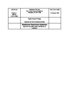
motors are working as expected, the left or the right motor is broken or both motors are broken. A broken motor provides no torque anymore. In [6] the authors describe how different hybrid automata can be efficiently combined to form an automaton for a system comprising different components. Moreover, the concept of hybrid automata can be extended by assigning probability values to mode transitions. This allows for selecting most probable transitions and thus provides a heuristics to improve searching for explanations, i.e., consistent states. Figure 3 shows a situation where our model of the differential drive (Fig. 2) is used in order to determine the current system state. The figure shows the real behavior of a robot and its intended behavior. After t : s the predicted and the observed behavior deviate which causes a transition from state ok Mr ok Ml to ok Mr ok Ml . Note that the right motor is not working correctly and, therefore, the robot is going along a circular trajectory instead of following the reference path as expected. Because in reality the observed behavior may deviate because of inaccuracies and uncertainties of measurements we use a tolerance interval. If the predicted value is within this interval no deviation and thus no inconsistency is said to be detected. The diagnosis procedure can be stated as follows:
= 22
: ( )^ ( )
( )^ ( )
1. Initialization: Let H comprise all states. Note that H comprise all possible states that are able to explain a certain behavior. 2. For all elements s H do:
2
(a) Compute the continuously valued state variables and output variables for the next point in time using the given input variables, the command variables and the behavioral model assigned to s. (b) If the computed output values are not consistent with the ob-
'velocity' of right wheel
drivepath of robot 0.4
0.5
0.4
vr
0.3 vr [m/s]
0.45
reference path path ok path faulty locations at k*Td
measurement of vr
0.2 0.1
0.35 0 y [m]
0.3
0
1
2
0.25
3
time [s]
4
5
mode estimate
0.2 mode number
4
0.15 0.1 0.05
3 2 1
0 0
0.1
0.2
0.3
0.4
0.5
0
0.5
1
1.5
x [m]
2
2.5 time [s]
3
3.5
4
4.5
Figure 3. The left diagram shows the execution of a path by a differential drive. The upper right diagram shows the velocity at the right wheel. After 2 s the right motor fails. This fact can be deduced from the decrease of the speed. The lower right diagram shows the estimated mode of the drive. 1 represents the nominal mode. 2 represents the :ok (Mr ) mode.
served values, then remove s from H . Search for state s0 which is connected with s where the computed next values are equivalent to the observed values and add s0 to H . 3. Goto 2 The described diagnosis procedure implements a multi-hypothesis tracking procedure where all hypotheses that explain the observed behavior with some level if confidence are element of H . This procedure can be improved by storing a limited number of hypotheses, e.g., only the 5 with the highest probability. If using a probability measure for ranking diagnoses, transition probabilities between states can be introduced in the hybrid automaton. More details about multi-hypothesis tracking can be found in [5, 9]. Once the diagnosis engine identifies the most likely diagnosis, a new model is generated which is used in the model-based motion controller. We explain the computation of the concrete model from the meta model of the kinematics of the system in more detail in the next section.
(e.g. due to a fault in the steering mechanism of a wheel) and thus have to take care of changed kinematic constraints during operation. Our meta motion model provides the specification for each wheel in terms of its geometric alignment with respect to the robots reference frame and the operational/fault modes for its actuation. Each wheel specifies a rolling and a sliding constraint for the robot’s kinematics.
yR
β(t) ϕ A l
r
α
v xR
P
4 Model-Based Controller The task of our model-based motion controller is to convert motion commands (immediate control signals) from the path planner/path executor into an appropriate actuation of the robot’s wheels. In detail, it converts a requested motion � � �_ R = x_ R y_ R �_ 0
_
(3)
into a desired rotational speed ' of the motors and, in case of a steered wheel, in its steering angle for each wheel of the robot. x and y denote the velocities of the robot along the axes of its local coordinate system. denotes the rotational velocity around the robots vertical axis. Low level control of each wheel will then take care of the appropriate actuation of the electrical drives. A typical way to do this is to take the robot’s kinematics configuration and derive a fixed relationship between the motion command and the wheel actuation. This is usually done by computing the instantaneous center of rotation (ICR) and the assigned rotational velocities for �R and assuming that a higher level path planner takes the kinematic constraints of the robot’s configuration into account. However, one considers the fault-free configuration at design time only. Our goal is different in that we allow changed configurations
_
_
�_
_
Figure 4. Parameters for a standard steered wheel. denotes the steering angle. ' is the rotation angle of the wheel. r , l and � define the geometry of the setup.
Figure 4 shows this specification for a standard steered wheel that leads to the rolling and sliding constraints shown in Equation 4. See [12] for the constraints of the most standard wheels. � �
� sin(� + ) os(� + ) l os� �_R r'_ = 0
os(� + ) sin(� + ) l sin �_R = 0:
(4) Combining the constraints of all (n) wheels of the robot, we obtain the vector-form of the constraints
J1 ( s )�_R J2 �_ = 0 C1 ( s )�_R = 0
(5) (6)
_
where s denotes the vector of all steering angles and � denotes the vector of angular speeds for the wheels. Please note that s can be a
function of time, e.g. steered wheels. The meta-model for the motion comprises simply the equations 5 and 6 for all possible operational modes. One can compute the space of the admissible motions through the null-space or kernel:
Z
Z = kernel(C1 ( s )) � IR3 :
(7)
_2Z
However, one has to make sure, that an admissible velocity � can be actuated (controlled) through the robot’s wheels, i.e. it leads to a non-trivial � in (5). Re-writing (5) we obtain
_
J2 1 J1 ( s )�_R = �_
(8)
and it becomes evident that we can compute the non-controllable velocities by means of
S�
(9) S� = kernel(J1 ( s )) � IR3 : Whenever the two spaces do intersect, i.e. Z \ S� 6= ;, we have to refine the admissible velocities Z to exclude those movements that cannot be actuated through the robot’s wheels. By computing the complement of S� S = kernel(S� T ) � IR3 ; (10) � denotes the matrix of basis vectors for S� we obtain the conwhere S trollable velocities so that the intersection
Z \ S =: �_
(11)
defines the space of admissible and controllable velocities for a given configuration of the robot. Our model-based controller deduces this vector space on-line for the configuration of the robot that is identified through the diagnosis engine [7]. Knowing this space, it checks whether a requested velocity from the path planner / path executor unit can be accepted through
�_R 2 �_ :
(12)
Whenever this condition holds, it proceeds with computing the robot’s instantaneous center of rotation (ICR), that, in turn, will lead to the steering angles i and angular velocities 'i for each individual wheel. Violating (12) indicates, that the current path of the robot is infeasible. The controller provides to the path planner so that this unit can derive an alternative path that is acceptable for the robot’s kinematics in the current (fault) configuration. It commits additional constraints to the high-level control. All changes within the kinematics that do not reduce the vector space for the admissible motions (typically single faults in a robot’s drives with some level of redundancy) are dealt with automatically, since the computation of the ICR and the consecutive deduction of steering angles and angular velocities utilizes a motion model (5-6) that reflects the currently active kinematic constraints of the robot (the concrete motion model) and not just the nominal fault-free case. In this sense, we obtain an automatic model-based configuration of the motion controller that directly handles an onset of single faults in the robot’s drive, recognizes the controller’s limits for re-configuration and communicates the relevant implications of changed kinematic constraints to the higher level control hierarchy. x
_
�_
5 Related Research and Conclusion Diagnosis and autonomous reconfiguration of autonomous systems has been in the focus of research for decades. There are a wide range of different approaches for diagnosis and reconfiguration. These approaches differ mainly in the used type of models (qualitative, quantitative or hybrid) and their deduction process (probabilistic state estimation, rule-based systems or logic inference). The Livingstone architecture proposed by Williams and colleagues [18] was used by the space probe Deep Space One to detect failures in the its hardware and to recover from them. The fault detection and recovery are based on model-based reasoning. In [3] and [16] particle filter techniques were used to estimate the state of the robot and its environment. These estimations together with a model of the robot were used to detect faults. The most probable state is derived from unreliable measurements. The advantage of this approach is that it is able to handle non-Gaussian uncertainties of the robot’s sensing and acting as well as uncertainties in its environment. Other approaches which are based on Kalman-filter are only able to account Gaussian uncertainties. In [14] the authors present a framework for detection and repair of faults in the control system of autonomous mobile robots. The framework used a model-based approach for fault detection. The information about the state of the system is mainly obtained from the observation of communication between software modules. The repair is done by a systematic restart of the effected software components. In [15] model-based diagnosis was used to establish a functional reconfiguration of a telecommunication system in order to ensure the desired functionality. In this application the reconfiguration was used to allow the system to incorporate new requirements. In this paper we present a framework which integrates modelbased fault diagnosis and reconfiguration of the hardware of an autonomous mobile robot. The aim of the framework is that a robot is able to fulfill its task even in the presence of faults. The robustness of a system which uses the framework is achieved by model-based reconfiguration of low-level control. In the case of a fault the system is able to retain the functionality. The presence of a fault is detected and identified using model-based diagnosis. The used motion model is a hybrid model composed of all kinematic constraints of the motion system. A general model is used for the diagnosis. A concrete model is used to reconfigure the system in case of a fault. Moreover, if the functionality could not be fully retained, at least the high-level controller is informed about this circumstance. The novel idea in this paper is the integration of autonomous diagnosis and reconfiguration in the same framework. Furthermore, the same meta-model about all possible operational modes of the hardware is used for fault diagnosis and reconfiguration which helps to reduce the amount of necessary modelling.
REFERENCES [1] J. Carlson and R.R. Murphy, ‘How UGVs physically fail in the field’, IEEE Transactions on Robotics, 21(3), 423–437, (June 2005). [2] H. Choset, K. M. Lynch, S. Hutchison, G. Kantor, W. Burgard, L. Kavarki, and S. Thrun, Principles of Robot Motion. Theory, Algorithms and Implementations, MIT Press, 2004. [3] Richard Dearden and Dan Clancy, ‘Particle filters for real-time fault detection in planetary rovers’, in Proceedings of the Thirteenth International Workshop on Principles of Diagnosis, pp. 1 – 6, (2002). [4] Readings in Model-Based Diagnosis, eds., W. Hamscher, Luca Console, and Johan de Kleer, Morgan Kaufmann Publishers, Inc., 1992. [5] M. W. Hofbaur, Hybrid Estimation of Complex Systems, volume LNCI 319 of Lecture Notes in Control and Information Science, Springer Verlag, 2005.
[6] Michael Hofbaur and Franz Wotawa, ‘A diagnosis-based causal analysis method for concurrent hybrid automata’, in Proceedings of the 16th International Workshop on Principles of Diagnosis (DX05), pp. 81–87, (2005). [7] Johannes K¨ob, Modellbasierte Regelung eines Roboterfahrwerkes, Master’s thesis, Institute for Automation and Control, Graz University of Technology, 2005. [8] Jean-Claude Latombe, Robot Motion Planning, Kluwer Academic Publisher, eight reprint edn., 2004. [9] X. R. Li and Y. Bar-Shalom, ‘Multiple-model estimation with variable structure’, in IEEE Trans. Automatic Control, volume 41, pp. 478–494, (1996). [10] Robin R. Murphy, Introduction to AI robotics, MIT Press, 2002. [11] Raymond Reiter, ‘A theory of diagnosis from first principles’, Artificial Intelligence, 32(1), 57–95, (1987). [12] Roland Siegwart and Illah R. Nourbakhsh, Introduction to Autonomous Mobile Robots, MIT Press, 2004. [13] Gerald Steinbauer, Christian Deutsch, Gordon Fraser, Matthias Hagler, Arndt M¨uhlenfeld, Stefan Richter, Gernot W¨ober, and J¨urgen Wolf, ‘Mostly harmless team description 2004’, in Proceedings of the International RoboCup Symposium, (2004). [14] Gerald Steinbauer and Franz Wotawa, ‘Detecting and locating faults in the control software of autonomous mobile robots.’, in 19th International Joint Conference on Artificial Intelligence (IJCAI-05), Edinburgh, UK, (2005). [15] Markus Stumptner and Franz Wotawa, ‘Model-based reconfiguration’, in Proceedings Artificial Intelligence in Design, Lisbon, Portugal, (1998). [16] Vandi Verma, Geoff Gordon, Reid Simmons, and Sebastion Thrun, ‘Real-time fault diagnosis’, IEEE Robotics & Automation Magazine, 11(2), 56 – 66, (2004). [17] B. C. Williams and M. W. Hofbaur, ‘Hybrid estimation of complex systems’, in Hybrid Systems: Computation and Control, HSCC 2002, eds., C. J. Tomlin and M. R. Greenstreet, pp. 253–266. Springer Verlag, (2002). Lecture Notes in Computer Science LNCS 2289. [18] B. C. Williams et al., ‘Remote agent: To boldly go where no AI system has gone before’, Artificial Intelligence, 103(1-2), 5–48, (August 1998).