E-mail {bergenti,poggi}@ce.unipr.it. Abstract. Design patterns are .... matching graphs of fragments corresponding to pattern templates with the design model.
Improving UML Designs Using Automatic Design Pattern Detection Federico Bergenti and Agostino Poggi Dipartimento di Ingegneria dell’Informazione, Università degli Studi di Parma Parco Area delle Scienze 181A, 43100, Parma, Italy E-mail {bergenti,poggi}@ce.unipr.it
Abstract Design patterns are considered one of the most valuable tools to produce quality designs and a general-purpose technique to improve a design is to identify all pattern realizations and to apply well-known rules to improve them. This technique requires finding all pattern realizations used in a design and it is a rather tedious task. This paper shows the work in the literature on assistants for programmers and software architects and presents a system called IDEA (Interactive DEsign Assistant). IDEA is an interactive design assistant for software architects meant for automating the task of finding and improving the realizations of design patterns. Basically, IDEA is capable of automatically (i) finding the patterns employed in a UML diagram and (ii) producing critiques about these patterns. The core of IDEA is the module that automatically detects the pattern realizations found in the model that the architect is producing. When this module finds a pattern realization, a set of design rules are verified to test if the design could be improved. Any violation to these rules fires a critique that is proposed to the engineer as a possible design improvement. Currently, a prototypal implementation of IDEA is integrated with two popular CASE tools.
Keywords Automatic design pattern detection, Critique generation, Design pattern, UML.
1. Introduction The design of complex software systems has been shown a very difficult task [2] and support tools are always needed to produce quality designs. Design patterns are considered one of the most valuable tools the engineer can adopt in the design of complex systems. Moreover, from the early days of the research on this topic, patterns have been recognized as an important means to document existing designs [10]. Patterns are fundamental abstractions that an engineer can use to come to a better comprehension of a complex software design. One of the simplest, yet more powerful, techniques to improve a design is to use patterns whenever possible and to follow some well-known rules to realize them. The application of this technique to an existing design is tedious because it requires finding all pattern realizations used in the design. This obliges analyzing the diagrams comprised in the design to identify possible pattern realizations and then applying pattern-specific rules to improve the found realizations. The automation of this task is a desirable feature for an assistant intended to improve the work of the software architect. This paper shows the work found in the literature about automated assistants for programmers and architects and introduces a novel system, called IDEA (Interactive DEsign Assistant), that addresses the problem of automating the refactoring of existing designs exploiting design patterns to propose critiques [6,18].
2. Automated Assistants for Programmers and Software Architects Automated assistants are considered a valuable tool in mature fields of engineering and almost all CAD systems for electronics and mechanics provide, at least, model checking capabilities. A number of automated assistants have been developed to help the engineer in most of the phases of the software lifecycle. These assistants can be roughly classified into generative systems and critiquing systems. Generative systems help the engineer producing new artifacts using generative techniques, i.e., techniques generating solution from general-purpose solution templates. Critiquing
2
systems are meant to provide critiques on existing artifacts to improve their realization. They rely on analyzing existing artifacts and on suggesting improvement rules. Design patterns can be used to describe a complex software system in terms of higher-level abstractions than classes, objects and messages. Nevertheless, only a few automated assistant currently employ patterns as basic abstractions for design and reverse engineering. This is due to the fact that patterns are a suitable language for humans, but a rather complex language for automated systems: they derive from a concrete design experience and they can not be easily formalized, or can not be formalized at all. The first characteristic implies that an engineer could find a design solution quite similar to a pattern without noticing the resemblance. The second characteristic suggests that only experience can drive the engineer in using patterns and general-purpose rules stating where to use a particular pattern are not generally available. These characteristics suggest that engineers can take benefit from an automated assistant capable of criticizing their design choices with respect to design patterns. Such an assistant could analyze a design model to: -
find automatically all pattern realizations in order to assign a role to the design elements;
-
propose pattern-specific critiques directed to improve the design or to enforce design rules;
-
suggest alternative realizations of the patterns emphasizing the achievable improvements;
-
propose a pattern to solve a particular design problem, at least for those patterns having a formal application rule;
-
find recurrent design solutions that can be the base for new patterns.
Assistants could couple the listed processes with learning capabilities to model their behavior on the engineer’s design style. Design patterns can be exploited both in generative and critiquing systems because they represent general-purpose solution that (i) generative systems can adapt to specific problems and (ii) critiquing systems can use to come to a better comprehension of the existing artifacts. The
most
famous
automated
assistant
for
software
engineering
is
the
Programmer’s
Apprentice [15,16] developed at the MIT Artificial Intelligence Laboratory by Rich and Waters. 3
This system uses a knowledge base about software design and implementation to detect errors made by the programmer or to select implementation choices automatically. This knowledge base is expressed in terms of clichès, i.e., “commonly used combinations of elements with familiar name” [16]. The primary difference between a clichè and a design pattern is the level of abstraction. A clichè may represent an algorithm fragment or an abstract data type, but it does not say anything about the interaction between objects. This is the reason why clichès can be used to describe an object implementation but they cannot represent an object architecture. The low level of abstraction that characterizes clichès allows the Programmer’s Apprentice to detect their occurrences in source codes and design models easily. More recently, Argo/UML [19,20], a CASE tool developed at the University of California by Robbins, Hilbert and Redmiles, integrates a CASE tool with an automated assistant. Argo/UML supports UML and provides the engineer with online critiques about the model under construction. These critiques range from simple naming conventions to suggestions about possible design improvements. Argo/UML selects the critiques searching particular structures in the current UML model. The selected critiques are then proposed to the engineer in a to-do list. Anyway, Argo/UML does not incorporate a knowledge base about design patterns because the structures it uses to fire the critiques are too fine-grained. As an example, it checks for classes without operations or informs the engineer to adopt names strictly related to the application domain, avoiding names such as adapter or proxy. A tool capable of exploiting the information contained in a design model at the pattern level was proposed, but no longer supported, by Florijn, Meijers and van Winsen [4,11]. This tool is capable of detecting all pattern realizations in an OMT model and to exploit this information to associate a set of roles to the classes composing the detected pattern realizations. The detection algorithm is based on fragments. These are typed design elements that can be composed to represent the elements of an OMT model. The pattern detection is performed matching graphs of fragments corresponding to pattern templates with the design model. 4
Design patterns and similar structures are widely used in reverse engineering tools to extract highlevel knowledge from a source code. One of the most famous systems that try to do this is PAT (Program Analysis Tool) [8,9] developed at the University of Illinois by Harandi and Ning. PAT is an analysis and debugging tool that detects events, that are abstract concepts contained in a code, and uses them to describe plans [8]. Plans are high-level views of a code that capture properties that can be used for documentation or re-engineering. Plans are lower-level concepts than design patterns because they are intended to work with source codes written in an imperative language. The extension of this approach to object-oriented languages and design patterns is proposed by many other systems [1, 3, 7, 11, 13, 17, 21, 22]. These systems are designed to work off-line and to process a source code to detect all pattern realizations. These systems help the generation of highquality documentation directly in the code or in the first steps of the re-engineering process. Anyway, source code analysis can be applied too late in the development process to represent a valuable tool in the design phase. IDEA (Interactive DEsign Assistant) is a critiquing system that we developed to work in direct interaction with the software architect to propose pattern-specific critiques. This task is performed detecting all pattern realizations in the UML design under construction and selecting suitable critiques intended to improve them. IDEA takes as input an UML design exported in XMI format and uses the class and collaboration diagrams in it to detect all pattern realizations. If the information needed to detect a pattern can be acquired from these diagrams, IDEA can detect it and we call it detectable. Some pattern fall out of this category because they are not completely defined in terms of classes, objects and interactions, and we call these patterns undetectable. This is the case, for example, of patterns such as the Façade or the Interpreter [5]. These patterns are characterized by their role in the whole design rather than by their structure and therefore their automatic detection would require an overall comprehension of the model. This comprehension requires a deep understanding of the diagrams comprised in the design and nowadays no system capable of performing this task is available. 5
When a pattern realization is found, IDEA checks pattern-specific rules to select a set of critiques directed to improve this realization. Each critique is statically associated with a high, medium or low importance that quantifies the relevance of the corresponding rule violation. These critiques are directed to improve the pattern realizations suggesting: -
names for classes, attributes and operations: for example, the name of a factory method in the Factory Method pattern should end with the suffix Factory;
-
a scope for operations: for example, hook methods in the Template Method pattern should be declared protected to access them only through template methods;
-
operations that are likely to be missing in a class, such as an operation to access the components of a composite object in the Composite pattern;
-
operations that are likely to be dangerous for reusability, such as providing a direct access to the subject of a proxy object in the Proxy pattern;
-
techniques that can be used to solve design problems: for example, the Iterator pattern can be used to access the components of a composite object in the Composite pattern.
It is worth noting that these critiques are pattern-specific and they require a high-level understanding of the design than usual style rules [12,14] do not require. Therefore pattern-unaware critiquing systems cannot provide such critiques. IDEA is extensible and customizable and the engineer can provide new patterns and new rules to select and fire new critiques. At the moment, the architect can customize IDEA implementing Prolog rules that are directly integrated in the knowledge base of IDEA. The implementation of a graphic tool to describe such rules is planned for a future activity. The help that IDEA can provide to the engineer is not limited to the proposal of rules concerning the patterns employed in a design. The automatic detection of the patterns in a model can represent a valuable tool to check the coherence between the concrete design and the actual engineer’s intentions. A discrepancy between the result of this process and the engineer’s intentions could raise the following consequences: 6
-
if the engineer wanted to employ a pattern but this can not be detected, probably the design is wrong or it can be improved;
-
the detection of a pattern where the engineer did not plan to use it may lead to a better comprehension and documentation of the design.
The following sessions describe IDEA in more detail and show the benefits that it can provide in the production of quality designs exploiting the so called GoF patterns, i.e., the patterns identified by Gamma, Helm, Johnson and Vlissides [5].
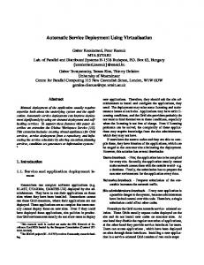
3. IDEA IDEA pattern detection process provides the engineer with two lists, the pattern list and the to-do list. The pattern list is the list of all patterns that IDEA found in the UML model. Each pattern in the list is characterized by a name and by a list of participants. Each participant is associated with the role it plays in the pattern. The to-do list is the list of all selected critiques ordered by their importance. IDEA dynamically maintains these lists adding and removing items when necessary. Moreover, IDEA allows the engineer controlling the pattern detection directly through the pattern and to-do lists. If the engineer explicitly removes a pattern or a critique, IDEA does not propose it anymore until the corresponding structure in the model changes. Figure 1 shows the class diagram of a realization of the Composite pattern and a tabular view of the output of the pattern detection.
3.1
Design-pattern Detection Algorithm
The design-pattern detection algorithm is the core of IDEA because it allows gathering the information needed to provide useful critiques to the engineer. This algorithm is responsible for the analysis of the class and collaboration diagrams of the UML design model to acquire all available information. This process cannot be easily formalized because of the informal nature of patterns. Even if a design pattern is always presented with a reference solution, the simple detection of this solution in the UML model is not always satisfactory. For example the Façade pattern solves the
7
problem: “Provide a unified interface to a set of interfaces in a subsystem. Façade defines a higherlevel interface that makes the subsystem easier to use” [5]. The proposed solution is a set of general guidelines that should be adopted to realize a Façade pattern, but it does not represent a template that can be used to detect all realizations of this pattern in a model. This is a consequence of the fact that the Façade pattern identifies a particular role of a class in a model, but this role can be expressed only in terms of an overall comprehension of the model. Similar problems are met when trying to detect patterns requiring a fine-grained understanding of the model. For example, the Singleton pattern solves the problem: “Ensure a class only has one instance, and provide a global point of access to it” [5]. The detection of a realization of the Singleton pattern requires finding a condition forcing the number of singleton objects to one. This condition cannot be easily expressed in a UML model, and it is often expressed only informally or it is not expressed at all. These problems prevent IDEA from detecting many of the design patterns found in the literature, anyway the number of detectable patterns and the number of related critiques suggest that IDEA can provide a valuable help to the engineer. The pattern detection algorithm has a cascaded structure comprising four steps, as shown in figure 2. First, the class diagrams are exploited to detect groups of classes that may represent a pattern realization. Then, the collaboration diagrams are used to refine this detection matching the object interaction with pattern-specific object interactions. The third step consolidates the obtained results gathering the pattern realizations that are detected more than once, as the rules used for the detection can find a single pattern realization many times. This happens, for example, when a pattern comprises a base class with an unspecified number of derived classes. To keep the detection rules simple, the base class is requested to have only one derived class. This implies that IDEA detects as many pattern realizations as the number of derived classes actually used in the model. The purpose of the consolidation step is to gather these realizations into a single realization. The last step of the pattern-detection algorithm presents the obtained results to the engineer.
8
Each pattern in the knowledge base is described in terms of a structure template and a collaboration template. Both these types of template are internally described as Prolog rules. The structure template identifies pattern-specific constraints that a portion of a class diagram must satisfy to belong to a pattern realization. For example, the structure template of the Template Method pattern states that such a pattern is made by an abstract class that contains, at least, two different operations. The structure template in not enough to detect the realizations of a Template Method pattern because almost any class satisfies these constraints. We use the collaboration template to exploit pattern-specific constraints on the collaboration diagrams and to refine the detection performed through the structure template. For the case of the Template Method pattern, we require the existence of an object whose formal class is the abstract class detected by the structure template in a collaboration diagram. Then, we require that the collaboration diagrams contain at least two calls: one to the template method and another to the hook method. Moreover, the hook method must be called by the instance of the abstract class to itself. As a final requirement, we impose the hook method to be called after the template method and this call must return before the call to the template method returns. The knowledge base of IDEA is completed with a set of design rules, with the corresponding critiques, and with a set of consolidation rules. Design rules are used to fire the critiques: when a design rule is violated, the corresponding critique is fired and proposed to the engineer. For example, the following are two design rules for the Template Method pattern: -
hook methods should be declared protected;
-
a common naming convention is to use the prefix do for hook methods.
These rules have medium importance because their violation does not represent a serious problem for the reusability of the design. Consolidation rules are used to face the problem of multiple detection of the same pattern realization. The application of both design rules and consolidation rules is straightforward because they are implemented as Prolog rules in the knowledge base of IDEA. 9
3.2
System Architecture
IDEA is based on a modular design that has two main objectives: to allow its integration with existing CASE tools and to support various user interfaces. The first constraint is imposed by the desire to promote the use of IDEA and this can be achieved only supporting off-the-shelf CASE tools. At the moment, IDEA is integrated with two popular CASE tools: Rose from Rational and Argo/UML [20] from the University of California. The second constraint derives from the extreme importance that the user interface plays for automated assistants. IDEA proactively prompts the engineer with the results of its analysis and this must not be annoying. For this reason, IDEA supports various user interfaces that can be selected with a simple configuration tool. The design of IDEA can be split into three major modules: the input module, the reasoning engine and the user-interface module. The input module is delegated to constantly retrieve the current UML model from the CASE tool. This process depends on the available CASE tool, but it is often sufficient to read the back-up copy of the model that the CASE tool constantly saves. Once retrieved, the class and collaboration diagrams are extracted from the model and they are transformed into a standard representation. To allow the engineer to directly interact with the pattern detection process, the input module supplies also a model-dependent knowledge base to the reasoning engine. This knowledge base is created by the input module to reflect the information that the user provides by means of the user interface. This information allows modifying the pattern detection process to suppress critiques or falsely detected patterns. The reasoning engine is delegated to analyze the model retrieved by the input module with respect of the available knowledge base. This knowledge base comprises a model-dependent part provided by the engineer and a model-independent part used to detect the pattern realizations. The modelindependent knowledge base is loaded at launch-time and can be completely customized by the engineer providing new Prolog rules. This part of the knowledge base contains the set of design rules with associated critiques and the set of detectable design patterns. The reasoning engine uses this knowledge base to produce the pattern list and the to-do list and then exploits the model10
dependent knowledge base to filter these lists to remove the entries explicitly cancelled by the engineer. The reasoning engine passes the produced lists to the user interface module to show them to the engineer. Currently, IDEA supports two user-interface modules, one for the integration with the Rational Rose and one for Argo/UML. The first uses Microsoft Agent to provide an anthropomorphic assistant similar to Microsoft Office assistants. The latter integrates the results and IDEA critiques with the critiquing engine provided by Argo/UML. Figure 3 shows an Argo/UML window containing a class diagram and a report window generated by IDEA. The report window contains two tables that provide information about all the realizations of the Abstract Factory pattern detected in the model. The first table shows the results obtained using only the structure templates, while the second shows the results obtained considering also the collaboration templates. The rows of these tables contain the roles defined in the pattern, while the columns, except for the first, enumerates the detected pattern realizations. In the example shown in figure 2, the report window contains the four roles defined in the Abstract Factory pattern and just one pattern realization. IDEA is implemented completely in Java and it integrates a small Prolog interpreter written in Java. Anyway, user interfaces are most likely implemented using native code when the CASE tool is not platform independent. This is the reason why the integration with Rational Rose requires a tool we developed called Observer to allow IDEA interacting easily with the engineer. The integration with Argo/UML does not require such techniques because Argo/UML is distributed with full source code. Moreover, Argo/UML already provides the tools needed to implement an interactive critiquing system. IDEA is completely integrated with Argo/UML: it adds a menu to ask for services such as report windows and it also integrates the critiques about the design patterns directly in the critique folders.
11
4. Detecting GoF Patterns The knowledge base of IDEA contains the rules for detecting a subset of the GoF patterns [5] and this section presents such rules. These rules are expressed using a particular convention [4] suggested by an analysis of many patterns found in the literature. Patterns heavily rely on inheritance to realize reusable class architectures, anyway they never require the inheritance relations to be direct. For example, the Proxy pattern requires that the proxy class inherits from the subject class, but it does not forbid the engineer to add another class between these two classes. This added class inherits from the subject class and it is inherited by the proxy class. This degree of freedom is the reason why, in the rest of this section, the word inheritance does not refer to direct inheritance, but it refers to a possibly cascaded inheritance. The Adapter pattern can be realized using two different structures, one is based on multiple inheritance while the other is based on single inheritance. These Adapter realizations can be detected using a structure template that selects triplets of classes: target, adapter and adaptee. In the Adapter realization based on single inheritance, the adapter inherits from the target and is associated with the adaptee. On the contrary, the adapter realization based on multiple inheritance requires that the adapter inherits both from the target and from the adaptee. In both these cases the target must contain at least one abstract operation implemented by the adapter and the collaboration template requires the implementation of this operation to be partially delegated to the adaptee. The detection of the Bridge pattern requires finding a triplet of classes: abstraction, implementor and concrete implementor. The concrete implementor inherits from the implementor and implements, at least, one of its abstract operations. The abstraction and the implementor are related by means of a one-to-one containment association. The collaboration template states that, at least, one of the operations in the abstraction must delegate its responsibilities to one abstract operation of the implementor. The Composite pattern can be detected searching for all triplets of classes: component, composite and leaf. Composite and leaf inherit from the component class and each composite object contains a 12
set of components with no restrictions on the cardinality of the containment. The complete detection of the Composite pattern is performed using also a collaboration template. The composite class must implement at least one abstract operation inherited from the component and this operation must delegate part of its responsibilities to the component objects. The Decorator pattern is quite similar to the Composite pattern and it can be detected following similar rules. In the simplest case, the collaboration templates are identical, while the structure templates are slightly different. In fact, the Decorator pattern requires the containment association to be one-to-one. When the design contains more than one decorator class, the Decorator pattern is composed of four classes for the introduction of an abstract decorator class, but this modification does not change substantially the detection rules. The Factory Method pattern involves four classes: the product, the concrete product, the creator and the concrete creator. The concrete product inherits from the product and the concrete creator inherits from the creator, but only the creator is abstract because it contains an abstract operation that is implemented in the concrete creator. This operation is the factory method and so it must return a product object. The first hint about the presence of a Factory Method pattern in a class diagram is the presence of a create association between the concrete product and the concrete creator that allows concrete creator objects to create concrete product objects. The collaboration template refines this detection choosing the creator operations that send a create message to a concrete product object. The detection of the Abstract Factory pattern can be based on the detection of factory methods. In fact, one of the possibilities to implement an abstract factory is to create an abstract class containing a factory method for each product family. This suggests that an abstract factory can be detected searching for all abstract classes containing a factory method. The Iterator pattern is composed of four classes: the aggregate, the concrete aggregate, the iterator and the concrete iterator. The aggregate and the iterator classes are abstract and they are implemented respectively by the concrete aggregate and the concrete iterator. The aggregate 13
provides a factory method, implemented by the concrete aggregate, that can be used to produce iterator objects. The structure template can be completed with an association between the iterator and the aggregate or between their concrete counterparts. This association is directed from the iterator, or the concrete iterator, to the aggregate, or to the concrete aggregate. The collaboration template is particularly important for the detection of the Iterator pattern because the constraints imposed by the structure template are too weak. Such a template requires the iterator object to be used to navigate the corresponding aggregate object. This can be expressed stating that the iterator object must be used mainly within loops containing at least two calls to its operations. In fact, the iterator object is used, at least, for two purposes: to access the current element in the aggregate and to move to the next element in the traversal. Generally, the iterator object is also used for the termination condition of the loop, but this is not a necessary condition and it cannot be used to detect the pattern. The Observer pattern requires the presence of four classes: the subject, the observer and their implementations, the concrete subject and the concrete observer. The subject is associated with a set of observers and the association allows, at least, reaching the observer from the subject. The concrete observer is associated with the concrete subject and this association is one-to-one and allows the concrete observer to access the concrete subject. This association can be substituted with an association, with the same properties, between the observer and the subject. The concrete observer must implement, at least, one of the abstract operations of the observer. The collaboration template exploits these operations to impose a characteristic object protocol. The protocol is initiated by a real subject object calling an abstract operation on all observer objects. Then, each observer object delegates a part of its responsibility to the subject object that initiated the protocol calling an abstract operation implemented by the concrete subject. A possible alternative is that some observer object decides to call directly a concrete subject object without using the indirection provided by the subject class.
14
The detection of a Prototype pattern requires finding two classes, the prototype and the concrete prototype, connected by an inheritance relation. The prototype must define an abstract clone operation and the concrete prototype must implement it. This operation can be identified easily in languages such as C++ or Java. In fact, the clone operation in C++ is the copy constructor, while in Java this operation is called clone and all classes have it because it is inherited from the class Object. The Proxy pattern is composed by three classes: the subject, the real subject and the proxy. The real subject and the proxy are associated and both inherit from the subject. All public operations in the subject are abstract and the collaboration template requires they to be all implemented by both the proxy and the real subject. Moreover, each inherited operation in the proxy must be partially delegated to the real subject.
5. Conclusions The use of design patterns is considered fundamental for the production of quality designs and a general-purpose technique to improve an existing design is to search for all pattern realizations to apply well-known rules to improve them. This technique involves finding all pattern realizations employed in a design and therefore it is a rather tedious task for the engineer. This paper presents the work found in the literature about automated assistants for the programmer and the software architect and introduces IDEA, a design assistant meant to provide online, pattern-oriented help to the architect. IDEA works with the architect in the production of an UML model providing critiques about the pattern realizations found in the model. IDEA analyses the model, finds all pattern realizations employed in it and then proposes critiques directed to improve these realizations. The core of IDEA is the module that automatically detects the pattern realizations in the UML model. The engineer is not required to adopt a modified UML notation because IDEA knows a set of well-known patterns and exploits this knowledge to perform the detection autonomously. This process is implemented analyzing the class and collaboration diagrams comprised in the model to 15
match them against pattern-specific structures. Class diagrams are used to identify groups of classes that can constitute a pattern realization. Collaboration diagrams refine this detection matching the object interactions with pattern-specific interactions. When IDEA finds a pattern realization, it verifies a set of design rules to test if this realization can be improved. Any rule violation fires a critique that is proposed to the software engineer as a possible improvement for the design. Currently, IDEA recognizes a subset of the GoF patterns and it is integrated with two popular CASE tools.
Acknowledgements We would like to thank Massimiliano Gerardi for the implementation of some relevant parts of IDEA. This work is partially supported by “Progetto di Ricerca Applicata 5% del CNR – Multimedialità”.
References 1 2 3 4
5 6 7 8 9 10 11 12 13
J. Bansiya, Automating Design-Pattern Identification. Dr. Dobb’s Journal, 1998. F. P. Brooks, No Silver Bullet: Essence and Accidents of Software Engineering. IEEE Computer, Vol. 20, No. 4, 1987. K. Brown, Design Reverse-Engineering and Automated Design Pattern Detection in SmallTalk. Available at http://www2.ncsu.edu/. G. Florijn, M. Meijers and P. van Winsen, Tool Support for Object-Oriented Patterns. Proceedings of The European Conference on Object-Oriented Programming - ECOOP'97 (1997). E. Gamma, R. Helm, R. Johnson, and J. Vlissides, Design Patterns: Elements of Reusable Object-Oriented Software. Addison-Wesley, 1995. A. Girgensohn, End-User Modifiability in Knowledge-Based Design Environments. Ph.D. Thesis, University of Colorado, 1992. D. Gruijs, A Framework of Concepts for Representing Object-Oriented Design and Design Patterns. Technical Report INF/SCR-97-28, Utrecht University, 1997. M. Harandi and J. Ning, Knowledge-Based Program Analysis. IEEE Software (January 1990). M. Harandi and J. Ning, PAT: a Knowledge-Based Program Analysis Tool. Proceedings of the Working Conference on Reverse Engineering (1988). R. Johnson, Documenting Frameworks using Patterns. Proceedings of the Conference on Object-Oriented Systems, Languages and Applications, (1992) 63-76. M. Maijers, Tool Support for Object-Oriented Design Patterns. Technical Report INF/SCR96-28, Utrecht University, 1996. S. Mayers, Effective C++: 50 Ways to Improve Your Programs and Designs. AddisonWesley, 1992. Parasoft. Programming Effectively in C++. Available at http://www.parasoft.com/. 16
14 15 16 17 18 19 20
21
22
R. S. Pressman, Software Engineering: A Practitioner's Approach. McGraw-Hill, 1992. C. Rich and R. Waters, The Programmer’s Apprentice: A Research Overview. IEEE Computer, Vol. 21, No. 11, 1988, 10-25. C. Rich and R. Waters, The Programmer's Apprentice. Addison-Wesley, 1990. C. Rich and C. Wills, Recognizing a Program's Design: A Graph-Parsing Approach. IEEE Software, Vol. 7, No. 1, 1990, 82-89. J. E. Robbins, Design Critiquing Systems. Available at http://www.ics.uci.edu/. J. E. Robbins and D. F. Redmiles, Software Architecture Critics in the Argo Design Environment. Knowledge-based Systems, Vol. 11, No. 1, 1998. J. E. Robbins, D. M. Hilbert and D. F. Redmiles, Argo: a Design Environment for Evolving Software Architectures. Proceedings of the 1997 International Conference on Software Engineering (1997). M. Sefika, A. Sane and R. H. Campbell, Monitoring Compliance of a Software System with Its High-Level Design Model. In Proceedings of the International Conference on Software Engineering - ICSE'96 (1996). F. Shull, W. L. Melo and V. R. Basili, An Inductive Method for Discovering Design Patterns from Object-Oriented Software Systems. Technical Report UMIACS-TR-96-10, University of Maryland, 1996.
17
Figure 1. Realisation of the Composite pattern and some of the selected critiques.
Pattern List
T o-do List
Composite
High
A realisation of the Composite pattern. Graphic graphics add(Graphic) remove( Graphic)
Graphic
Rectangle Leaf
Picture Rectangle
Component
Picture
Composite
Do not put the reference to children in Graphic, put it in Picture only. Consider adding getGraphics() in Picture. Consider using the Iterator pattern to access Graphic objects in Pi cture. Consider maintaining a reference to the parent from the children.
Graphic should define as many common operations for Rectangle and Picture as possible.
18
Figure 2. Architecture of the pattern-detection algorithm.
UML Model
Match Structure Templates with the Class Diagrams
Structural properties of patterns are used for detection.
Refine with Collaboration Templates and Collaboration Diagrams
Object interactions are used to refine the detection.
Consolidate the Detected Patterns and Select the Critics
Merge the pattern realisations that are detected more than once.
Show the Detected Patterns and the Selected Critics
Critics
the the
Patterns and critics are showed to the engineer.
Patterns
19
Figure 3. Argo/UML with a report window generated by IDEA.
20