Automatic Service Deployment Using Virtualisation Gabor Kecskemeti, Peter Kacsuk MTA SZTAKI Lab. of Parallel and Distributed Systems H-1518 Budapest, P.O. Box 63, Hungary {kecskemeti,kacsuk}@sztaki.hu Gabor Terstyanszky, Tamas Kiss, Thierry Delaitre University of Westminster Centre for Parallel Computing 115 New Cavendish Street, London, W1W 6UW
[email protected]
Abstract Manual deployment of the application usually requires expertise both about the underlying system and the application. Automatic service deployment can improve deployment significantly by using on-demand deployment and selfhealing services. To support these features this paper describes an extension the Globus Workspace Service [10]. This extension includes creating virtual appliances for Grid services, service deployment from a repository, and influencing the service schedules by altering execution planning services, candidate set generators or information systems.1 2
1. Introduction 1.1. Service and application deployment issues Researchers use complex software applications (e.g. BLAST, CHARMm, GAMESS-UK) deployed by site administrators. They have to run their applications on those sites where they have been installed. Researchers cannot use those Grid resources, where their applications are not deployed. These applications are so complex that users usually cannot deploy these on new sites. Even if they could have deployed these applications, site policies in production Grid environments usually do not allow users to deploy 1 This research work is carried out under the FP6 Network of Excellence CoreGRID funded by the European Commission (Contract IST2002-004265) 2 The EDGeS project (RI - 211727) receives Community research funding.
new applications. Therefore, they should ask the site administrators to install and configure the applications, they need. The deployment may raise some licensing and maintenance issues at each site. Applications may have strict licensing conditions, and the Grid site providers probably do not want to bind themselves to these conditions, especially when the licensing is not free of charge. Even if licensing problems can be solved, the complexity of these applications may require knowledge from the site administrators, which they may not have. If users have the source codes and they are able to compile these, they have binaries of the applications, which can be staged to the executor site eliminating the deployment. However, this solution has several drawbacks: Users drawback - First, the application has to be compiled for every site. Secondly, the application usually cannot make network connections with the outside world - e.g. a database. Finally, the submission has to prepare the executor environment for the application every time. Networks drawback - Frequent submission of the executable increases the network traffic. Site administrators drawback - Every new application is a possible danger to the system, because administrators have limited control over this code. Therefore, a single submission could affect other codes. Nowadays the Grid moves towards service- oriented solution. These Grids usually expose codes deployed on the site and do not install new codes on executor sites. At one hand they disable the regular execution of applications, at the other hand they provide service interfaces for users. Users can access applications , which have been deployed on sites through these interfaces. Installing a new application in a service-oriented Grid consists of two main steps:
1. Deploying the application, installing dependencies, configuring it, preparing network connections, etc. 2. Providing a service-oriented interface: to access application and deploy it on a Grid service container. This service interface could be either a generic or specific one. A generic interface is provided by a Grid middleware (e.g. OGSA-BES basic execution service implementations and JSDL job submission description language repositories) or other generic application wrappers (e.g. Application Hosting Environment (AHE) [4], Grid Execution Management for Legacy Code Application (GEMLCA) [5], Generic Application Service Factory (gFac) [9]). A specific interface is tuned for the application and written by either the application developers or by the user community. Manual deployment of the application usually requires expertise both about the underlying system and the application. In several cases it cannot be done without the assistance of the system administrators. There is a need for a solution that can perform deployments without any specific expertise. This solution should also act between the limits the system administrators gave to the user. These kinds of solutions are called automatic service deployment systems and they can both deploy the application and activate the service interface for further uses.
1.2. Deployment automation Automatic service deployment can improve deployment significantly by using on-demand deployment and selfhealing services. In case of on-demand deployment the applications are retrieved from a repository and installed and configured on the target site prior its execution. The deployment could be initiated by a broker or an advance reservation system. The on-demand deployment uses either centralised or distributed repositories. Centralised repositories store all the required and dependent software packages in the same location with their configuration. In distributed repositories, packages are spread around the Grid. Distributed repositories either store pre-packaged software components and they have references to their dependencies or software components are distributed around the Grid using some replication solutions. On-demand deployment increases the risks of using grid sites maliciously. The newly deployed software components might interfere with the already deployed ones, the software installed might need outgoing network connections, therefore on every local hardware resource (e.g. disks, network, processing power) the service should have strict limitations according to the service level agreements [13]. If malfunction occurs in a Grid service and the source of malfunction can be identified the service can reconfigure
or reinstall the affected components. Service faults can be recognized through advance fault prediction or active service calls. Advance fault prediction uses component monitors to determine service misbehavior. Active service calls can generate regular output messages or fault messages. If the service response is a fault message the service should identify the cause of the fault which could be internal or external. In case of internal causes the component causing the fault should be repaired. If the service responds with a regular response message the response has to be validated against the semantics of the service and violations should be reported back to the service initiating the self-healing process. There are two major approaches for automatic deployment: service-oriented and non-service-oriented solutions. The service-oriented solutions operate at service container level. Therefore they are not capable to handle the background applications management tasks. The non-serviceoriented solutions manage the service container as a common software component on which the currently deployed software depends.
1.3. Virtualisation and deployment Automatic service deployment could be further improved by using virtualisation. The new hardware architectures give more and more support for virtualisation. Therefore, the software also has to tackle this issue. The application and its service interfaces are preinstalled with all of their dependencies in a virtual machine image as a virtual appliance to be executed on one of the destination sites virtual machines. Therefore the deployment incorporates the installation and activation of virtual appliances. Grid researchers have already developed some solutions in this area, for example: the XenoServer platform [12], or the Workspace Service (WS) [10] for Globus Toolkit 4 [6]. Service deployment with virtualisation can support both the on-demand deployment and the self-healing services in a secure way even at the site level. Using virtualisation techniques, the software repository for on-demand deployment should hold the virtual appliances of the services. The requirements against the hosting environment should also be stored together with the virtual appliances because the virtual appliances are virtualisation technique dependent. Virtual machines could also provide restrictive domains for the software deployed in them. Therefore the limitations e.g. outgoing network bandwidth, IP address declared in the service level agreements of the site can be enforced via the virtualisation software [13]. In order to support selfhealing, virtual appliances should be distributed in several packages a base package, and delta packages. The base package is a minimal and roboust package on which the delta packages are built. It should contain the necessary
components to configure and install further components of the application before their execution, and it should be capable to reinstall these components when malfunction arises. The delta packages should represent those software components which the self healing service is able to repair. The delta packages should be distributed with their individual configuration details in order to support on-demand reconfiguration. The paper is organised on the following way. Section 2 discusses related works, Section 3 gives an overview on the deployment architecture, Section 4 describes an advanced virtual appliance creation service, Section 5 provides solutions to alter an an execution schedule to include deployments, and Section 6 reviews the current implementation, finally Section 7 concludes this work.
2. Related Works WS [10] (workspace service) as a globus incubator project supports wide range of scenarios involving virtual workspaces, virtual clusters and service deployment from installing a large service stack like ATLAS to deploying a single WSRF service if the Virtual Machine (VM) image of the service is available. The WS is designed to support several virtual machines XEN [2], VMWare, VServer to accomplish its task. The XenoServer open platform [12] is an open distributed architecture based on the XEN virtualization technique. It is aiming for global public computing. The platform provides services for server lookup, registry, distributed storage and a widely available virtualization server. VMPlants [11] project proposes an automated virtual machine configuration and creation service heavily dependent on software dependency graphs. This project stays within cluster boundaries. These solutions are focusing on the deployment process itself and do not leverage their benefits on higher levels. Meanwhile the solution presented in this paper is focusing on possible extensions on the current deployment systems by integrating the openness of the XenoServer platform, the widespread virtual machine support of the Workspace Service, and the DAG based deployment solution presented by the VMPlants. This paper also introduces higher-level services supporting the service lifecycle on grid architectural level.
3. Automatic Service Deployment In order to support automatic service deployment, the WS interface has to be extended by two new services: Automated Virtual Appliance Creation Service (AVS). It should support service deployment by creating
virtual appliances for Grid services. The virtual appliances should be stored in an appliance repository, for example in the Application Contents Service [8] (ACS). The ACS provides a simple interface for managing Application Archives (AA) [8], which hold both the application packages and their configuration. The WS should access the contents of the service by using the endpoint references provided by the ACS for each AA. The virtual appliances (or service images) should be minimized because the repository may hold large number of virtual appliances. As a result, a virtual appliance shrinker should optimize the appliances archive even if it is using different formats of the different virtualization techniques such as XEN, VMVare or VirtualPC. Scheduler Assistant Service (SAS). To define the sites where the service can be installed and select among these sites, the AVS should be used together with the OGSA [7] Execution Planning Service (EPS), more precisely, its Candidate Set Generators (CSG). CSG can define scheduling candidates for sites, which are capable of deploying a service in a reasonable time. CSG, may define sites where the service have not yet deployed. EPS should resolve these schedules in two ways: Schedule-driven deployment. The EPS has to insert extra deployment jobs in the schedule, which install and configure the service on the specified site. Container-managed deployment. The EPS does not need to deal with the deployment tasks because at the first service call the service container should deploy the service from the repository.
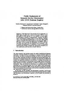
3.1. The deployment process with the proposed architecture The process of the service deployment with WS based on XEN VMs, presented on Figure 1., contains two phases: virtual appliance creation and service deployment phase. Phase 1 Virtual appliance creation : 1. The client (an entity wishing to publish a Grid service as a virtual appliance e.g. Grid service developer, or Grid scheduler who has made schedules for a Grid service already deployed on a site but not available in any repositories) asks the AVS to store the Domain Ms VM image of Grid site A with a Grid service in it in an AA instance.
VM Image Store
where ACS, AVS, WS are interfaces
ACS
I1
I2
I3
In Service 3
Grid Site A, XEN Domain 0 XEN Domain M Service
2
9
6
Client 1
AVS
4
7
WS 5 10
8
Grid Site B, XEN Domain 0 XEN Domain M Ii Service
’
Fig. 1 Automatic Service Deployment Figure 1. Automatic Service Deployment 3.1 The deployment process with the proposed Step 4 – AVS acknowledges the virtual architecture appliance ( or image) creation by sending ACS Endreturns Point the Reference to the 2. AVS generates a basic virtual appliance from the 9. its WSFactory client the(EPR) WSs EPR. TheXEN process of theM. service deployment with client. [2] Domain If its size can be decreased, 10. The client forwards any further service requests WS based on XEN VMs,(orpresented Phase to2 the– re-deployed Service Grid Deployment from the service shrinks optimizes)ontheFigure virtual1., apservice in Site B. If aneccontains two phases: virtualappliance appliance repository pliance. The optimized has creation a base apessary it manages the VM instance through the and service deployment Step previously 5 – The client (an EPR entity(VM having an ACSand pliance and severalphase. delta packages. The base apreceived termination Phase pliance 1 – Virtual appliance creation: EPR, e.g. a regular user initiating a should be capable to install and configure configuration changes). Stepthe1delta – The client (an entity wishing to deployment, a Grid broker trying to load packages. publish service and as thea delta virtual balance between sites) asks the Service WS toand The Automated Virtual Appliance Creation 3. AVS storesatheGrid base appliance packappliance – e.g. Grid service developer, or deploy the VM image using the ACS the Scheduler Assistant Service are described in EPR. Section 4 ages in an Application Archive (AA) instance, Grid scheduler who has made schedules for Step 65, respectively. – WSFactory requests the ACS to and Section and adds the configuration and dependency to a Grid service already deployed on a site provide the AA instance and WS support deployment requests. but not available in any repositories) asks configuration details. 4. Automatic Virtual Appliance Creation Ser4. AVS acknowledges virtual appliance or imthe AVS to storethethe Domain M’s ( VM Step 7 – The VM image is transferred to the viceGrid (AVS) age) creation bysite sending its ACS End Point Refimage of Grid A with a Grid service in Site B erence (EPR) to the client. it in an AA instance. Step 8 – WS creates a virtual workspace The Automatic Appliance Creationusing Service 2 –Deployment AVS generates a basic virtual accordingVirtual to the configuration thecrePhase 2Step Service from a repository : ates and stores virtual appliances in an ACS repository appliance from the XEN [2] Domain M. If VM image provided by the AA instance. [8] to make the available for WS. service 5. The client (an entity having an ACS EPR, e.g. a its size can be decreased, the service Step 9 appliances – WSFactory returns the The client the is built on the ACS-WS interface, which enables deployment regular user initiating a deployment, a Grid broshrinks (or optimizes) the virtual appliance. WS’s EPR. in Grids. WS to deploy virtual ker to load balance between Thetrying optimized appliance hassites) a asks basethe StepThe 10interface – The should client enable forwards any further appliancesservice retrieved as AA instances from an ACSGrid reposiWS to deploy theseveral VM image using the ACSThe EPR. appliance and delta packages. requests to the re-deployed tory. The service AA instances store appliances and their base appliance should be capable to install in Site B.the If virtual necessary it manages 6. WSFactory requests the ACS to provide the AA states. The state of the virtual appliance is composed of WS and configure the delta packages. the VM instance through the previously instance and WS configuration details. resource properties VM configuration parameters. Step 3 – AVS stores the base appliance and the received and EPR (VM termination andThis 7. The VM image is transferred to the Grid Site B service has the followingchanges). functionality: delta packages in an Application Archive configuration 8. WS creates a virtual to the (AA) instance, andworkspace adds the according configuration The Automated Virtual Appliance Creation configuration using to the support VM image provided by Creating appliances. AVS Service service are impleand dependency deployment Service virtual and the SchedulerThe Assistant the AA instance. ments AVS-WS interface. The first implementation requests. described in Section 4 and Section 5, respectively. of
this service uses the XEN Virtual Machine [2]. The service provides four operations. First, it generates an AA instance. Secondly, the service instructs the XEN VM to make a disk and memory image of the domain and store these images in the AA instance. Thirdly, it collects a VM setup, such as XEN domain specific setup and if exists, the network shaping setup for the Domain 0 VM and convert these parameters into WS resource properties. Finally, it uploads the state of the VM image to the AA instance. This service is similar to the technologies provided by virtual appliance builders like (rBuilder), however it provides higher level of automation for preparing appliances on already deployed systems. Optimizing virtual appliances. To minimize the size of virtual appliances, they should be shrinked. Efficient image shrinking can be achieved by active fault injection, which is a flexible dependency detection algorithm. Each WSRF (Web Services Resource Framework) service should be checked by a junit test to optimize and validate the image shrinking process. The subsystem dependencies detected during the shrinking process should be stored for future use, for example in a CDL [3] (Configuration Description Language) document or in a model driven deployment descriptor. Repackaging the appliance. The service builds deployment DAGs [11] to define deployments. These DAGs are built on top of configuration and installation nodes. Each DAG starts from a base virtual appliance which is replicated over the Grid sites. Therefore, the optimal selection of the base appliance is crucial. The system has to make compromises between transfer time and on site deployment time. If there no suitable base appliance is available, the service will not modify the shrinked appliance. Identifying base appliances. The AVS regularly analyzes the AAs and checks the similarities of their deployment DAGs [11]. The similarities mean common roots in the DAGs. Figure 2 presents multi package (Px) deployment strategies for 2 services (Sx). The dashed packages are the similar deployment tasks in the two deployments. If the similar items exceed a systemlevel threshold, then the common nodes can be stored in a base virtual appliance (BVa). This base appliance is going to be spread over the Grid by replication. Finally, the Application Archives used for building the base virtual appliance has to be revised. The archives should build on this newly created base appliance. The deployment of an archive built on a base appliance is composed of two phases: first the base appliance is deployed, and then this base appliance is started in a selfhealing state. During the self-healing process the base
Figure 2. Service Deployment DAGs appliance will install then configure all the necessary packages for proper service operation.
5. Scheduler Assistant Service (SAS) This service, built on an ACS repository [8] and usually prepared by the AVS, helps to define a schedule to execute a service request taking into consideration both those sites where the service has been deployed and where it could be executed but has not yet been installed. If the deployed services are not available, it checks whether any of the latter Grid sites can deliver the service taking into account the deployment cost.
5.1. OGSA-EPS Bindings OGSA-EPS [7] has two main connections with the outside world: the Candidate Set Generators, and the Information Services. In order to influence the schedules the EPS makes, the assistant service could be installed on any of the following components or on their combination: Candidate Set Generators. The scheduler assistant generates extra candidate sites for execution. These sites are the ones where the requested services have not been deployed. In case new candidates were added container managed deployment has to be supported, otherwise the SAS has to give hints to the EPS about the newly added sites to take into consideration the deployment tasks. Execution Planning Services. The scheduler assistant queries the CSG to retrieve the list of sites, which can handle the service request. If no site can deliver the requested service the EPS makes a decision upon the results of the second query and adds two
separate entries to the schedule an optional one for the deployment task, and one for the real job, the service call. Information Services. The scheduler assistant generates virtual entries in the information services. Since both the CSG and the EPS heavily rely on the IS the assistant can include information which might alter their decision. This information states service presence on sites where the service is not even deployed. The QoS information stored in the virtual entries are degraded from the level the service would perform after deployment. However even this degraded level can look promising on among highly overloaded sites. This solution has serious problems compared with the previous two ones. The IS has to be filled with the full service site matrix, which could increase query times and load on the IS nodes. Non-realistic information is introduced in the information systems this might affect some systems. Installation of the assistant service or services next to an OGSA-EPS enabled site depends on the grid policies. The assistant will be able to cooperate with an existing EPS as a CSG or an IS source, or it can offer a new, enhanced EPS on deployment enabled Grids.
5.2. CSG improvements The CSG assistant is a distributed, ontology-based adaptive classifier [14], to define a set of resources on which a job can be executed. The CSG can build its classification rules using the specific attributes of the local IS. Each CSG may have a feedback about the performance of the schedule made upon its candidates in order to further improve its classification rules using a semi-supervised learning. The CSGs build a P2P network and the EPSs candidate nomination request might spread over the neighboring CSGs for refinement the request is sent when the quality of the current candidates is below a certain limit. Ontology helps to bridge between the distinct attribute sets of the ISs because the different CSGs might work on different attribute sets. When a new Grid with a CSG is deployed it inherits the rules of the neighboring classifiers at the startup. The P2P network can support more than just the decision-making process, e.g. it can also improve the ontology by analyzing the analogies between the different rule sets. A SAS extended CSG has three interfaces to interoperate with other CSGs and the EPS. CSGs form a P2P network. This network has two interfaces; the first interface manages the ontology of different ISs by sharing the classifier rules and the common ontology patterns distributed as an OWL schema, while the second interface supports decision-making this interface is similar to the one between the EPS and CSG, however the new in-
terface provides details about the decision making progress and WS-Addressing details of the EPS who made the original query this way the P2P the final candidate set can be sent directly to the EPS without traversing back through the network. The third interface lays between the EPS and the CSGs to support the supervised learning technique applied by the CSGs the EPS sends back a metric packet including the success rate to the CSG the candidates were originated.
5.3. EPS improvements The EPS assistant has different implementations depending on how the other parts of the SAS are deployed. If both the CSG assistant and the EPS assistant is deployed then the EPS can make smarter decisions. After receiving the candidate resource-set the EPS estimates the deployment and usage costs of the given service per candidate. To estimate the deployment costs the EPS queries the WS with an ACS endpoint reference, which identifies a particular virtual appliance. As a result, the WS should be extended with this capability. The usage costs also include, for example the cost of the inter-service communications e.g. if a service is deployed closer to its dependencies then the communication costs decrease. Therefore, the EPS sends software agents to estimate the change in the communication cost between the affected endpoints (e.g. it checks for latencies and available bandwidth). The SAS has a plug-in based architecture in order to support different agents discovering different aspects of the deployment. If the EPS assistant is deployed alone then the EPS generates deployment jobs on overloaded situations (e.g. when a given job can not be completed by the user specified wall time), these deployment jobs are the service calls to the WS with the proper ACS EPR. The EPS estimates execution wall times through the WS interface discussed in the previous paragraph.
5.4. IS improvements The IS assistant provides information sources on sites which can accept service calls after deployment. The SAS calculates the necessary metrics specified by the GLUE schema [1] like EstimatedResponseTime, WorstResponseTime. Etc.) for each site in the Grid according to the local service availability, and publishes them as ServiceData. The SAS-enabled Grid services build on the fact that the ACS EPR is available for the services under submission. Further deployments use this EPR to initiate the installation process on the selected site. Therefore, the most crucial point in the system is about the place of the repository references. The SAS can collect these references from three locations: • UDDI is the original service repository, which can hold metadata for each service, if this metadata is a
valid ACS EPR the SAS uses it for deployments. • GLUE-Schema has Service entries per site, every service entity has a ServiceData map which holds key value pairs for extended use of the schemas information. One of the ServiceData objects in the per service description should be the ACS EPR. • WSDL can be customized and further extended as described in the W3C standards. The WSDL can describe which virtual appliance was used for instantiating the service by including an ACS EPR element after the service element the WSDL. As a consequence both the GLUE schema and the UDDI is supported without the extensions on them, because they both hold references to the WSDL the service conforms with. SAS assumes this behavior throughout its operation.
ACS ext
ACS dVA
VA
5
Site boundary
2
HeadNode ACS
WS
1
N1
N2
N3
N4
3 BaseVA
4
Figure 3. VA Staging with AAStagingAdapter
6. Implementation 6.1. Extension of the Workspace Service The Workspace Service has a plugin based architecture to support different sources of virtual appliances. To suppot automated deployments a virtual appliance repository has to be connected with the WS. This leads to an extension of the WS with a new kind of StagingAdapter called AAStagingAdapter. This adapter accepts Application Archive EPRs as inputs and uses the ACS service to transfer the requested virtual appliance to the target node. It also can intelligently detect whether the remote ACS service, which holds the AA, supports the extensions introduced later in Section 6.2. Its behavior changes on the following way (see figure 3 for details): Direct VA download. A generic ACS holds the whole image of the VA therefore it can be downloaded directly to the target node (see steps 1-2 on figure 3). Two phase VA download. An extended ACS can build the VA locally. This way the plugin requires the Base VA to be stored in the ACS repository next to the workspace service. This makes the AAStagingAdapter capable to deploy the BaseVA on the target node (step 3-4), then query and apply the differences stored on the remote Application Archive (step 5). With this solution the external network is much less used on the price of the local VA creation. The policy about which download scenario the AAStagingAdapter is going to use can be influenced by the configuration of the extended WS. The adapter estimates the required time building a new VA. The estimate is based on the size(s) of the remote differential AA(s) and the previous construction times of appliances built on top of the same BaseVA.
Using this estimate the adapter decides whether the available AAs from regular ACSs are worth the bandwidth and time to spend.
6.2. ACS as a Virtual Appliance Store There are three major features included in our ACS service: Transport methods for large files. The ACS specification requires only the embedded and WS-Attachment based AA transmission to be supported by all the implementors. This requirement is not suitable for Virtual Appliance transfer, because the sizes of the VAs can be quite large. A large file transfer may torment the web services container of the ACS, and therefore disrupt other WSRF services deployed right next to the ACS service. An ACS supporting VA transfer should provide other transfer methods like GridFTP, RFT or HTTP(s). Our implemented ACS uses GridFTP or HTTP alternatively for AA transfer. Remote differential Archive support. Other important requirement against the ACS to provide differential AAs based on a remote AA EPR. The ACS specification defines the differential Application Archive Descriptor (AAD) on the way that an AA cannot build on an AA which is not present in the repository. The AAD is extended to include a remote AA EPR if it is needed. This way the ACS can download the referred AA and then update it like it would with the local one. Finally it can serve the complete AA bundle as a regular one. Based on the request frequency of an AA the ACS decides to store the served AA for later use or drop it to conserve disk space.
Plugin for understanding archive contents. In order to build on top of the base Virtual Appliances the ACS has to be able to inject the differential AA’s contents to the base appliance. This is achieved by content activated plugins for our ACS system. Currently two plugins are available. One for adding extra zip entries to an archive containing a single zip file (this is for demonstration purposes only). And one is for AAs containing VAs. If an AA contains a VA then the ACS detects it and the VAHandler plugin is activated. This plugin initiates the base VA using the extended Workspace Service. After the base VA is running the VAHandler orders it to download and activate the differential update required. These two operations are available as Web Services in the base VAs developed for the ACS service. The current implementation of the base VA is a web service wrapper around the debian package manager. For security reasons the services offered by the BaseVA are accessible only from the local network. Each ACS plugin is bound to a BaseVA type. If more than one BaseVA is defined then new plugins has to be written.
7. Conclusion and future work This paper defined an infrastructure on which an automated service deployment solution can build on. It has covered the lifecycle of service and application deployment from the packaging to the execution. The self-healing base virtual appliances provide higher availability of the services deployed with the AVS. Meanwhile the SAS gives us grid services on demand. Therefore grid users no longer bound to the sites where the applications they used are deployed and made publicly available. In the future the interface of the self healing virtual appliance has to be further developed to support local and system wide malfunction alerts, and self monitoring systems. The published on demand deployment solution should be further generalized to support future deployment scenarios. Also the SAS should be extended towards seamless integration with other execution management subsystems in OGSA like CDDLM [3].
References [1] S. Andreozzi, S. Burke, L. Field, S. Fisher, B. Konya, M. Mambelli, J. M. Schopf, M. Viljoen, and A. Wilson. Glue schema specification version 1.2, 2005. [2] P. Barham, B. Dragovic, K. Fraser, S. Hand, T. Harris, A. Ho, R. Neugebar, I. Pratt, and A. Warfield. Xen and the art of virtualization. In ACM Symposium on Operating Systems Principles (SOSP), 2003.
[3] D. Bell, T. Kojo, P. Goldsack, S. Loughran, D. Milojicic, S. Schaefer, J. Tatemura, and P. Toft. , configuration description, deployment, and lifecycle management (cddlm) foundation document, 2005. [4] P. V. Coveney, M. J. Harvey, and L. Pedesseau. Development and deployment of an application hosting environment for grid based computational science. In UK All Hands Meeting, 2005. [5] T. Delaittre, T. Kiss, A. Goyeneche, G. Terstyanszky, S.Winter, and P. Kacsuk. Gemlca: Running legacy code applications as grid services. Journal of Grid Computing, 3(1-2):75–90, June 2005. [6] I. Foster. Globus toolkit version 4: Software for serviceoriented systems. In IFIP International Conference on Network and Parallel Computing, 2005. [7] I. Foster, H. Kishimoto, A. Savva, D. Berry, A. Djaoui, A. Grimshaw, B. Horn, F. Maciel, F. Siebenlist, R. Subramaniam, J. Treadwell, and J. V. Reich. The open grid services architecture, version 1.5, 2006. [8] K. Fukui. Application contents service specification 1.0, 2006. [9] G. Kandaswamy, D. Gannon, L. Fang, Y. Huang, S. Shirasuna, and S. Marru. Building web services for scientific applications. IBM Journal of Research and Development, 50(2/3), March/May 2006. [10] K. Keahey, I. Foster, T. Freeman, X. Zhang, and D. Galron. Virtual workspaces in the grid. ANL/MCS-P12310205, 2005. [11] I. Krsul, A. Ganguly, J. Zhang, J. Fortes, and R. Figueiredo. Vmplants: Providing and managing virtual machine execution environments for grid computing. In SC04, Pittsburgh, PA., 2004. [12] D. Reed, I. Pratt, P. Menage, S. Early, and N. Stratford. Xenoservers: Accountable execution of untrusted programs. In 7th Workshop on Hot Topics in Operating Systems, Rio Rico, AZ, 1999. IEEE Computer Society Press. [13] V. Talwar, S. Basu, and R. Kumar. An environment for enabling interactive grids. In IEEE International Symposium on High Performance Distributed Computing (HPDC-12), Seattle, Washington, June 2003. [14] M. E. Taylor, C. Matuszek, B. Klimt, and M. Witbrock. Autonomous classification of knowledge into an ontology. In The 20th International FLAIRS Conference (FLAIRS), Key West, Florida, May 2007.