ISSN 2394-3777 (Print) ISSN 2394-3785 (Online) Available online at www.ijartet.com International Journal of Advanced Research Trends in Engineering and Technology (IJARTET) Vol. 3, Special Issue 16, March 2016
Improving Visual Quality Beautification Using Qr Code M.Suganyaa [1], M.Shanmuga Priya[2],C.S.Puvana [3],C.Vijayalakshmi[4]. Project Scholar- MKU [1], Student[2],[3],[4]. ULTRA College Of Engineering And Technology For Women, Madurai, Tamil Nadu, India Email id:
[email protected] Abstract---Quick Response (QR) code is a widely used matrix bar code with the increasing population of smart phones. However, QR code usually consists of random textures which are not suitable for incorporating with other visual designs. QR code can be capture using mobile phones to acquire information through QR code reader.In past years, researchers have been tried to beautify the QR code with their taste and preference and it has been formulated as an optimization problem that minimizes the visual perception distortion subject to acceptable decoding rate. The Proposed system havetwo-stage approaches, In the first stage, GaussJordan elimination procedure is used to reliable decodability. In the second stage, a rendering mechanism is designed to improve the visual quality. Keywords—Threshold; Quick Response (QR); Premask; Russ Cox’s.
I. INTRODUTION Increasing popularity of QR Codes (Quick Response Code) by using smart phones to retrieve information of specific objects in our day to day life and some application can be build based on QR code. QR-Codes are 2-dimensional bar codes that, in essence, contain some bits of encoded information using Reed-Solomon (RS) error-correcting codes.while decoding QR scanner cannot acquire the pixel correctly. Like all matrix code technologies (Semacode, Aztec Code, etc), QR-Codes are commonly used to identify objects or redirect the user to a website.Itis now popular and widely used owing to its low cost ofcreation, large data storage capacity, and instant readability. QR codes are utilized in a spreadof applications, like accessing websites, Air tickets,food production,contact lens Management,patient wristband etc… In the past,embedding the image is the main aim of the researchers additionally they tried to change the shape and colors of the QR code.Generally the characteristic of QR code beautification can impress the viewers and also give uniqueness to the customers. However, it has limitationsin size constraint of the embedded picture, visual quality of the generated QR code.
In order to overcome the shortcomings of noise-like looks of QR codes, we propose a systematic QR code beautification framework where the visual appearance of QR code is composed of visually meaningful patterns selected by users, and more importantly, the correctness of message decoding is kept intact. Our work makes QR code from machine decodable only (i.e. standardized random texture) to a personalized form with human visual pleasing appearance. We expect the proposed QR code beautifier can inspire more visual-pleasant mobile multimedia applications. Several methods have been proposed to automatically beautify QR code through picture embedding Embedding visual content into a QR code without affecting its readability and it also reduce the error tolerance.
Developed Visualead, a Visual QR Code Generator,it having a concentric region of modules cannot be changed and similarly blend the neighboring regions with image content. Their specific idea is to preserve the original difference between modules while blending the image content and the QR code. However, their method results in serious block artifacts such as corruption at salient regions of the image content . Moreover, when the same image
29 All Rights Reserved © 2016 IJARTET
ISSN 2394-3777 (Print) ISSN 2394-3785 (Online) Available online at www.ijartet.com International Journal of Advanced Research Trends in Engineering and Technology (IJARTET) Vol. 3, Special Issue 16, March 2016
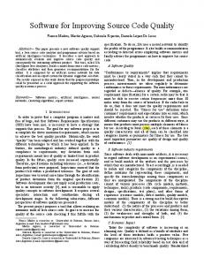
content is applied to different QR code, the result quality of the visual QR code varies a lot.Optimization problem that minimizes the visual perception distortion subject to acceptable decoding rate. Here, error aware warping technique is used to deform the embedded image. The binary exampler is to change the regular shape of the QRcode (normally QR code is in square shape). We propose an approach to produce high quality visual QR codes; it also called halftone QR codes. In this work, we have two stage approaches, 1. A baseline of QR code is generated by modifying the control bits using Gauss Jordon Eliminationprocedure and it also reducesthe error tolerance. 2. We further improve the visual qualityof QR code without affecting the decodability using EllipseGradient mask in Rendering Mechanism. II. OVERVIEW QR Code is the Two-dimensional black and white modules. These modules contain the control bit informations.The Version number is allocated for size of the Qr Codes and its named as version V.The size of the QR code have the (17+4V)*(17+4V) modules. Generally QR code generation have Four Error correction stage i.e. Level L Approx. 7% of codeword scan be restored. Level M Approx. 15% of codeword scan be restored. Level Q Approx. 25% of codeword scan be restored. Level H Approx. 30% of codeword scan be restored).The decodable QR code is briefly explained as follows. First analyze the Embedded message to determine the suitable version number V.Then to find the error correction level of QR code. The embedded message is encoded into k bit stream with Zero padding(0000).Next apply the Reed Solomon code(RS Code) to correct to the k bit stream which result is generating t parity bits. while reading the QR code the parity bits are used to detecting and correcting the error. At last, n bit RS code generated (The n bit RS code includes bits for message bits, bits for padding bits, and bits for parity bits) and also generate the Function Pattern for improving the reading performance of the QR code(i.e. the finder pattern, the alignment pattern, and the timing pattern).These are Embed into the QR code with the Pre masking. As illustrated in Fig. 2(a), the blue/green/red regions indicate where the message/padding/parity bits are placed in the QR code, respectively. Each message bit is placed onto one module of the blue region in a vertical
boustrophedon order starting at the bottom right corner, while each padding/parity bit is placed Onto one module of the green/red region in the same manner.
The beautication of QR code is formulated by optimization problem that is distort the visual Quality to an acceptable decoding rate. According to optimization problem are solve to generate the accurate result. In this work, we proposed two levels of approaches, in first stage, the baseline of the QR code is generated with reliable decodability based on the Gauss Jordon Elimination Procedure for modify the control bit selection. In second stage, visual quality of QR code is improved without affecting the decodability of QR code in Rendering mechanism. Here these two stages are completed within the 0.8 second and it also efficient for real time applications.
30 All Rights Reserved © 2016 IJARTET
ISSN 2394-3777 (Print) ISSN 2394-3785 (Online) Available online at www.ijartet.com International Journal of Advanced Research Trends in Engineering and Technology (IJARTET) Vol. 3, Special Issue 16, March 2016
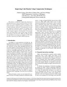
Fig.3 Explain the system architecture design for QR Code beautification. Taken input image as I. we aim to make the Resultant QR Code IR.which have the high decodable and high quality of I. That is, the color of a module mi in IR should be similar to the color of a pixel pi in I. then the input image I is threshold in LAB color space for generate two binary images: first one is pixel based binary image Ip and module based binary image I’m.. The pixel-based binary result obtained by thresholding each pixel independently according to a fixed threshold, and the module-based binary result acquired by assigning each module a binary value according to the averaging value of all pixels inside the central region of the module. Then function pattern is applied to both pixel based and mudule based binary images. We taking the module based binary image I’mand apply the pre-mask it to keep the recognizable pattern finding and process the QR cod synthesis method to generate the baseline of QR code IB with robust decodability. In QR code synthesis level, Russ Cox’s method is proposed. RussCox’s method are used to generate and make some modification on control bit selection. The generating Baseline QR code image IB is really effective for overcome the noise but it have the block artifacts when compared the original input image I. To improve the visual Quality of QR code we future process the rendering mechanism using the input image I and baseline QR code image IB and generate the resultant QR code IR. We will detail the QR code synthesis stage and the QR code rendering stage in the following sections. III. QR CODE SYNTHESIS To increase the decodability and reduce noise while decoding of QR code. collection of pixels are combined into module has 1-bit information. In synthesis method, module based binary image IM
taken as reference image and the baseline of the QR code IB is generated and it protect the most important content of the module based binary image IM while keep its readability. Then we adopt the Russ Cox’s method used to generate and make some modification on control bit selection . Fig. 2 illustrates the main idea. Fig. 2(a) shows the QR code obtained by using the conventional way to place the RS decodable bit stream BQ for the -bits message. Fig. 2(c) shows the module-based binary image IMand the corresponding 2D bit stream BM . Our goal is to perform operations on bits of BQ and transform it into a new bit stream BN , as shown in Fig. 2(b).
Fig.2(a) shows that an n bits(contain n,k,t) RS code is composed of k control bits includes encoded message,terminator symbols and padding bits with generation of parity bits used for detect and correct the error during readability of QR code. The process of RS code word is to generate the valid RS code from two different RS codes using XOR operation. We call the first three bits the control bits since their values control the values of the parity bits. Among the basis set, there is only one basis having the 1 value on each control bit. If we want the second, third, and fourth bits to be the control bits, we have to replace RS2 by XOR operation of RS1 and RS2.The
31 All Rights Reserved © 2016 IJARTET
ISSN 2394-3777 (Print) ISSN 2394-3785 (Online) Available online at www.ijartet.com International Journal of Advanced Research Trends in Engineering and Technology (IJARTET) Vol. 3, Special Issue 16, March 2016
corresponding RS codes of the basis set for the new control bits are then updated as,
row reduction on a matrix, one uses a sequence of elementary row operations to modify the matrix. This control bit selection strategy can be produce the much better results when compared the Cox’smethod. The parity bits are assigned to four border sides and preserve the visual content in the ROI (Region of Interest).Our Synthesis strategy in decodable QR code with less visual noise pixels.
The processof finding the valid RS codes for new basis sets {K1`,k2`,k3`}.it is achieved by using the Gauss jordon Elimination procedure with {RS1`,RS2`,RS3`}.Then we apply the XOR operation ot yield the RS code for ki`=011,110,101,111,and 000. The mentioned features of the RS codes are formulated by,
Where BQ is the original bit stream.BN is the targeted bit stream.∆ is the Gauss Jordon Elimination procedure.K` is the targeted control bits, and is the Targeted parity bits. We can change the positions of control bits in the bit stream to generate a new bit stream such that the control bits will be placed in the central part (ROI) of the 2D QR code .The RS code of the new basis set is obtained from the RS code of the old basis set by applying the Gauss Jordon Elimination Procedure .Moreover, we can set the values of the new control bits to be the same as the values in the ROI of IM and obtain the corresponding RS code by applying the XOR operation on the RS codes of the new basis set. As a consequence, a decodable QR code IB , which is similar to IM, can be generated. In Russ Cox’smethod, the QR code is divided into the salient region and non-salient region. As shown in Fig. 4(a), the salient (green) region is selected to be the control bits area. In contrast, we partition the QR code into two parts, i.e. border and central. As shown in Fig. 4(d), the green central area is selected to be the control bits area. Then applying the Gauss Jordon Elimination Procedure. In linear algebra, Gaussian elimination (also known as row reduction) is an algorithm for solving systems of linear equations. It is usually understood as a sequence of operations performed on the associated matrix of coefficients. This method can also be used to find the rank of a matrix, to calculate the determinant of a matrix, and to calculate the inverse of an invertible square matrix. To perform
IV. RENDERING THE QR CODE The Decodable QR code is described in the previous section, since the binary image contains the block artifact so the resultant QR code is not satisfied. To design the Rendering method in QR code beautification. Here we take the input image I and the pixel based binary image IP to be our consideration. The specific module M in the resultantQR code IR is composed of N*N pixels ( in N=9 our implementation). Chu et al[8] had proved that if we want to correctly decode a module of size 3*3 (pixels), at least the center pixel (i.e., 1/3 of the module size) should contain the correct information. we divide the module into central part has the pixel value of the rendered resultant QR code to ensure decodability and it based on the baseline of the QR code. Another one is non-central pixel the pixel value of the rendered resultant QR code to mitigate the block artifacts and it based on the pixel based threshold image IP. To be more precise, the brightness of each pixel (i,j) in a module of the resultant QR code is rendered by the following equation:
where is a parameter controlling the readability of the module m. When ,α=0 the resultant QR code is the same as the input image but the readability is zero.
32 All Rights Reserved © 2016 IJARTET
ISSN 2394-3777 (Print) ISSN 2394-3785 (Online) Available online at www.ijartet.com International Journal of Advanced Research Trends in Engineering and Technology (IJARTET) Vol. 3, Special Issue 16, March 2016
When ,α=1 the central part of each module is the same as IB , which is robust to noise while decoding. The non-central pixels are rendered is same as I P and its preserve the corner information of the input image I.We use the α constant value for each pixels.Simultaneously we using the constant α value to the entire QR code.it also reduce the cost function is automatically find the best α(x,y) for each pixel (x,y) in the resultant QR code IR.
δ(x,y) is an indicator function and δ(x,y) =1 when (x,y) is a central pixel; otherwise δ(x,y)=0 . The first term in the summation ensures that each central pixel in the resultant QR code IR should be similar to the baseline QR code IB such that the resultant QR code can be decodable. The second term in the summation ensures that each non-central pixel should be similar to the original image . The final term in the summation constrains α(x,y) to be similar to an ellipse gradient function as illustrated in Fig. 5, where px and py are set to be 1 and 1.5, respectively;
33 All Rights Reserved © 2016 IJARTET
ISSN 2394-3777 (Print) ISSN 2394-3785 (Online) Available online at www.ijartet.com International Journal of Advanced Research Trends in Engineering and Technology (IJARTET) Vol. 3, Special Issue 16, March 2016
cx and cy are the cen ter positions of the QR code’s width ( ) and height ( ), respectively. px and py control the values in the ellipse gradient mask and can be determined according to the size of paddingbit region, which is affected by two factors, i.e. the embedded message length and the error correction level. Therefore, instead of using fixed values,px and py can be adjusted by,
generated QR code. The another two mobile devices can successfully decode our QR codes with 100% decoding rate. The loss of decoding might result from the poor camera quality of the mobile device or improper values. For each QR code, we use ZXing decoder to decode the information
The error rate is computed by, where , β=2.9, γ=3.7 =3.7 ,m is the number of message bits, is the number of parity bits, and is the total number of bits in an RS code. The ellipse gradient mask ensures that modules nearby the image border would have larger values (i.e. have higher readability) and modules nearby the center region would have smaller values (i.e. preserve most visual content of the input image). Note that the minimization of the cost function is subject to and ,where is a Constant. To increase decoding rate to solve the minimization problem Thus by proposed system, visual quality and time complexity A variety of images were taken as the input images for embedding the source and it is based on four different methods, i.e. Visualead , Christo Ananth et al. [3] proposed a secure hash message authentication code. A secure hash message authentication code to avoid certificate revocation list checking is proposed for vehicular ad hoc networks (VANETs). The group signature scheme is widely used in VANETs for secure communication, the existing systems based on group signature scheme provides verification delay in certificate revocation list checking. In order to overcome this delay this paper uses a Hash message authentication code (HMAC). It is used to avoid time consuming CRL checking and it also ensures the integrity of messages. The Hash message authentication code and digital signature algorithm are used to make it more secure . In this scheme the group private keys are distributed by the roadside units (RSUs) and it also manages the vehicles in a localized manner. Finally, cooperative message authentication is used among entities, in which each vehicle only needs to verify a small number of messages, thus greatly alleviating the authentication burden.In Correctness of QR code decoding, it evaluated the correctness of decoded messages on three various mobile devices they are (Sony ZL, HTC butterfly, Redmi) with six different QR code decoders QR Droid, scanner pro QR code reader, QR BARCODE SCANNER, QR Code Reader, Qrcode Scanner, Neo Reader. The more variety of images are used to generate the beautified QR codes based on our method and the decoding rates are reported. If any one fail occurred when we used Sony ZL and Neo Reader to scan the
The error rate of each beautified QR code is less than 9.7% and the average error rate is about 3.0%, which means our beautified QR code is robust to be decoded correctly. The influence of px and pyin the rendering step, the values in the ellipse gradient mask are determined by and , which can be fixed values or can be adjusted according to the embedded message length and the error correction level.
A.Application: The nature of our rendering mechanism makes the resultant QR code superior to existing QR codes in term of visually quality. We further apply it to synthesize frame-by frame QR codes in video clips. Although the temporal coherence is not taken into consideration, the generated results are much more satisfactory than other methods because the visual content in the center part remains almost
34 All Rights Reserved © 2016 IJARTET
ISSN 2394-3777 (Print) ISSN 2394-3785 (Online) Available online at www.ijartet.com International Journal of Advanced Research Trends in Engineering and Technology (IJARTET) Vol. 3, Special Issue 16, March 2016
the same as the original video and the flickering effect only occurs around the frame boundary. The readability of the QR code is also robust as long as the PPI (pixel per inch) is large enough. V.CONCLUSION In this work, we propose an efficient twostage approach to generate QR codes with high quality visual content. A decodable baseline QR code with poor visual quality is first synthesized based on the Gauss-Jordan elimination procedure and then a rendering mechanism is designed to improve the visual quality while avoid affecting the decodability of the QR code. The experimental results show that the proposed method outperforms the existing worksconsidering the appearance of the QR code and the processing complexity is near real-time. REFERENCES
[1] T.-W. Kan, C.-H. Teng, and W.-S. Chou, “Applying QR code in augmented reality applications,” in Proc. 8th Int. Conf. Virtual Reality Continuum Appl. Ind., 2009, pp. 253–257. [2] T. Anezaki, K. Eimon, S. Tansuriyavong, and Y. Yagi, “Development of a human-tracking robot using QR code recognition,” in Proc. 17th Korea-Japan Joint Workshop Frontiers Comput. Vis., 2011, pp. 1–6. [3] Christo Ananth, M.Danya Priyadharshini, “A Secure Hash Message Authentication Code to avoid Certificate Revocation list Checking in Vehicular Adhoc networks”, International Journal of Applied Engineering Research (IJAER), Volume 10, Special Issue 2, 2015,(1250-1254) [4] T. Nikolaos and T. Kiyoshi, “QR-code calibration for mobile augmented reality applications: Linking a unique physical location to the digital world,” in Proc. ACM SIGGRAPH, 2010, pp. 144:1–144:1. [5] Y.-S. Lin, S.-J. Luo, and B.-Y. Chen, “Artistic QR code embellishment,”Comput. Graph. Forum, vol. 32, no. 7, pp. 137– 146, 2013. [6] H.-K. Chu, C.-S. Chang, R.-R. Lee, and N. J. Mitra, “Halftone QR codes,” ACM Trans. Graph., vol. 32, no. 6, pp. 217:1–217:8, 2013. [7] Y.-H. Lin, Y.-P. Chang, and J.-L. Wu, “Appearance-based qr code beautifier,” IEEE Trans. Multimedia, vol. 15, no. 8, pp. 2198–2207
35 All Rights Reserved © 2016 IJARTET