A live load test was conducted using tandem axle dump trucks under both quasi-static and ... Dynamic amplification and lateral load distribution were found to be ...
9th International Conference on Short and Medium Span Bridges (SMSB) Calgary, Alberta, Canada, July 2014
IN-SERVICE PERFORMANCE AND BEHAVIOR CHARACTERIZATION OF THE HYBRID COMPOSITE BRIDGE SYSTEM – A CASE STUDY John M. Civitillo University of Virginia, USA Devin K. Harris University of Virginia, USA Amir Gheitasi University of Virginia, USA Mark Saliba University of Virginia, USA Bernard L. Kassner Virginia Center for Transportation Innovation and Research, USA ABSTRACT The Hybrid Composite Beam (HCB) system is an innovative structural technology that has been recently used in bridge construction within the U.S. transportation network. In this system, the superstructure consists of a conventional reinforced concrete deck supported by Hybrid Composite Beams. Each beam is comprised of a glassfiber reinforced polymer (FRP) box shell containing a tied parabolic concrete arch. Inclined stirrups provide shear integrity and enforce composite action between the HCBs and the concrete deck. This paper focuses on evaluating the in-service performance of a newly constructed HCB bridge superstructure located on Route 205 in Colonial Beach, Virginia. A live load test was conducted using tandem axle dump trucks under both quasi-static and dynamic conditions. Results obtained from the experimental investigation were used to determine three key behavior characteristics. Dynamic amplification and lateral load distribution were found to be reasonable in comparison to the assumed design values. The testing program also included internal and external measurement systems to help characterize the load sharing behavior of the HCB on an element level. The main load carrying elements are the deck in compression and the steel ties in tension, and the FRP shell did not act compositely with the internal components. 1. INTRODUCTION 1.1 Background The Hybrid Composite Beam (HCB) system consists of a glass fiber reinforced polymer (FRP) box shell that encases a passively tied concrete arch. The tie reinforcement is unstressed prestressing strand that is integrated into the shell fabrication, while the arch is typically made of self-consolidating concrete that is able to fill the 100 mm thick arch profile created with foam inserts (Hillman 2008). Within the design, the concrete arch resists the internal compression forces due to self weight and additional construction loads, while the steel is intended to tie the arch together and carry internal tensile forces. Reinforcing bars oriented at a 45° and anchored within the arch section are distributed along the beam to provide composite action between the beam and a conventionally reinforced concrete deck. In this configuration, when the bridge is under service loads, the major load resisting components are the deck in compression and the steel in tension (Van Nosdall et al. 2013). The efficient use of materials, lightweight design, corrosion resistance, and application in accelerated construction applications are some of the advantages that make the HCB system an attractive alternative to conventional bridge designs (Hillman 2008).
Page-1
9th International Conference on Short and Medium Span Bridges (SMSB) Calgary, Alberta, Canada, July 2014
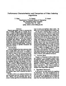
Figure 1: Hybrid Composite Beam Design (Hillman 2008) 1.2 Problem Statement The Virginia Department of Transportation (VDOT) was interested in deploying this design technology in a bridge, however, the agency wanted verification of the structural behavior of the HCB. Thus, the purpose of this investigation was to quantify some of the unknown behavior of this relatively new bridge technology, and how this skewed configuration performs relative to existing bridge design principles and existing HCB applications with no skew. Of particular interest was the flexural lateral load distribution behavior, the element load sharing behavior, and the dynamic load amplification of a skewed HCB structure. 2. EXPERIMENTAL PROGRAM This study examined the initial in-service behavior of a recently constructed HCB structure located on Route 205 over the Tides Mill Stream in Colonial Beach, VA. The construction involved replacing the previous concrete girders while maintaining the existing substructure. The HCB girders were 53 cm deep by 61 cm wide, and covered a 13.5 m clear span with a 19 cm cast-in-place composite deck. The girders were spaced at 1.2 m center-to-center, and the bridge measured 9.9 m transversely. The bridge carried two lanes of traffic, each with 0.9 m shoulders. The bridge spanned straight across a creek with two abutments on a 45° skew. In addition, the beams were made integral with the abutments by encasing the end sections of the beam in the abutment concrete. The in-service behavior of the system was evaluated through live-load testing. 2.1 Instrumentation Plan Although this particular investigation focused on the initial in-service performance of the HCB bridge, the instrumentation used on this structure was designed to serve two functions: 1) to yield measured responses during load testing and 2) provide long-term monitoring capabilities for the HCB bridge system. Two separate and complementary data acquisition systems were used to achieve this goal: the first system used a module recently developed module by Campbell Scientific Inc. (CSI) that is capable of dynamically measuring internally placed vibrating wire gages (VWG). The second system was a rapidly deployable wireless field testing system from Bridge Diagnostics Inc. (BDI) that measured externally mounted strain gages. Both systems were used during the load testing, but only the CSI system was intended for the long-term monitoring phase. Vibrating wire gages were installed internally on three of the HCBs at various stages in the fabrication phases (Figures 2 and 3). The locations selected for installation were determined in collaboration with VDOT and were intended to measure the HCB system behavior during load testing, but also over the long-term for inspection and evaluation purposes. Along the length of the beam, gages were installed at midspan and at both quarterspan locations to accommodate the influence of the skew. Additional gages were installed at the eighth points to measure shear response, but were not the focus of this particular study. At each longitudinal location, VWGs were installed during production of the composite girders at the location of the tension steel prior to infusion process of the FRP shell. Non-corrosive acrylonitrile butadiene styrene 3D printed frames were designed to hold two additional VWGs. These frames were installed in companion locations within the arch conduit prior to the placement of the arch Page-2
9th International Conference on Short and Medium Span Bridges (SMSB) Calgary, Alberta, Canada, July 2014
concrete. In addition, VWGs were affixed to the deck reinforcement at the same companion locations to provide a more comprehensive measure of the overall system behavior including the neutral axis location and level of composite action between the deck and girders.
Figure 2: Instrumentation Layout and Test Truck Loading Configurations (Cross-Section View) In conjunction with the internally placed gages, external strain gages were mounted on the FRP shell on the day of testing (Figures 2 and 3). These external gages were mounted on the bottom flange of each girder at midspan and the East quarterspan in order to capture distribution behavior of the bridge. Additional gages were mounted on the web of these girders at locations corresponding to the embedded VWGs in the arch (See Figure 2). These gages on the web gave an external strain profile that could be compared to the internal strain profile and help evaluate the load sharing behavior of the individual HCB components. Finally, two additional gages were mounted at midspan on the parapets to capture their contribution to the overall system behavior.
Figure 3: Instrumentation Bird’s Eye Overview Page-3
9th International Conference on Short and Medium Span Bridges (SMSB) Calgary, Alberta, Canada, July 2014
2.2 Load Test The load testing was performed by driving a load vehicle east to west across the bridge at predetermined transverse positions (Figure 2). The load truck used was a VDOT tandem-axle dump truck loaded with gravel, weighing 232 kN (80 kN front axle and 76 kN per rear axle). The truck was positioned in eight different transverse locations in order to elicit a maximum response from each of the eight girders during quasi-static testing, which consisted of driving the test vehicle across the bridge at a slow speed (