The Rational Unified Process (RUP) is a use case driven iterative software ...
design within the RUP involves user interface modelling and user interface ...
In Support of User Interface Design in the Rational Unified Process Chris Phillips and Elizabeth Kemp Institute of Information Sciences & Technology Massey University Palmerston North, New Zealand {C.Phillips,E.Kemp}@massey.ac.nz
Abstract The Rational Unified Process (RUP) is a use case driven iterative software engineering process User Interface design within the RUP involves user interface modelling and user interface prototyping. This paper describes two support artefacts - extended tabular use cases and UI element clusters - which provide a bridge between these two activities. They provide support for ‘flow of events’ storyboarding, the clustering of user interface elements and identification of UML boundary classes, and the initial sketching of user interface prototypes. Keywords: User interface design, Rational Unified Process, use case modelling, UML.
1
Introduction
The Rational Unified Process (RUP) is a use case driven iterative software engineering process (Jacobson, Booch and Rumbaugh 1999, Krutchen 2000). It is a descendent of Objectory (Jacobson, Christerson, Jonsson and Overgaard 1992) which has been further developed by Rational Software. The RUP is a customisable objectoriented framework which provides guidelines, templates and tools to support software development and component reuse. It incorporates best practices that can be tailored for a wide range of projects and is aimed at meeting the needs of end users. The models upon which the RUP is based are described using the Unified Modelling Language (UML) (Fowler and Scott 1997, Quatrani 1998, Richter 1999). UML consists of a collection of semi-formal graphical notations, and appears set to become the object-oriented modelling language standard (Kobryn 1999, Rumbaugh, Jacobson and Booch 1999, UML Revision Task Force 1999). UML provides for the construction of several views of a software system, and supports both static and dynamic modelling. The notations include use case diagrams, activity diagrams, class diagrams, interaction diagrams and state diagrams. Use cases are central to the RUP as they lay the foundation for subsequent development. They provide a functional (task) view, modelling the way an actor interacts with the system. Each use case describes one
Copyright © 2002, Australian Computer Society, Inc. This paper appeared at the Third Australasian User Interface Conference (AUIC 2002), Melbourne, Australia. Conferences in Research and Practice in Information Technology, Vol. 7. John Grundy and Paul Calder, Eds. Reproduction for academic, not-for profit purposes permitted provided this text is included.
use of the system, and involves the sequencing of interactions and (implicitly) the manipulation of objects. In UML, use cases are represented at a system context level in a use case diagram, which shows the system boundaries, the external actors, and any structural relationships which exist. UML provides no syntax aimed specifically at describing the detail of use cases, although activity diagrams can be employed to provide an outline workflow view. In Section 2, support for user interface design within the RUP is briefly reviewed. Section 3 describes use case storyboarding and introduces an extended tabular use case representation which assists with the identification of user interface (UI) elements. Section 4 describes how this supports user interface prototyping, through the clustering of UI elements, the identification of UML boundary classes, and the initial sketching of user interface designs.
2
The RUP and User Interface Design
User Interface design within the RUP involves two stages: user interface modelling and user interface prototyping. The main input to these activities is the use case model, which describes how the system is used. At the user interface modelling stage, each use case is described via a use case storyboard, which is a conceptual description of how a use case is to be supported by the user interface (Krutchen, Ahlqvist and Bylund 2001). It includes the following properties: 1.
Flow of events storyboard: a high-level textual description of the interaction between the actor and the system.
2.
Interaction diagrams: which provide a detailed graphical description of how objects interact in the realisation of the use case.
3.
Class diagrams: which provide a description of the boundary classes and relationships that participate in the realisation of the use case.
4.
Usability requirements: a textual description of requirements relating to the quality and ease of use of the system.
5.
References to the user interface prototype: references to the UI elements which make up the user interface, including those corresponding to boundary classes.
Properties 2 and 3 are supported directly – both class diagrams and interaction diagrams are part of UML.
Notation
Flow
Actor
Level of detail fair
Exceptions
not shown
User/system separation poor
Activity diagram Textual
explicit implicit
shown
fair
good
out of line
Tabular
explicit
shown
good
good
out of line
in situ
Other aspects visual can be lengthy can be lengthy
Figure 1: Comparison of use case representations Usability requirements (Property 4) are normally specified textually. The focus of the research reported here is on supporting properties 1 and 5. Support for ‘flow of events’ storyboarding is described in Section 3. Support for linkage to user interface prototyping is described in Section 4. The user interface prototyping stage involves the design and evaluation of both ‘lo-fidelity’ and ‘hi-fidelity’ prototypes. Lo-fidelity prototypes (Rettig, 1994), the focus in this paper, involve sketches and mockups, using paper and pencil and possibly ‘façade’ tools such as Microsoft PowerPoint.
3 The Use Storyboard
Case
‘Flow
of
Events’
The use case ‘flow of events’ storyboard is a high-level textual description of the interaction between the actor and the system which consists of brief action statements. It represents a step by step description of the corresponding use case (Krutchen, Ahlqvist and Bylund 2001). Use case behaviour, though, can be described in various ways. Whilst many commentators (e.g. Cockburn 2001, Fowler and Scott 1997, Richter 1999) support the need for detailed textual use case descriptions, there is no agreement on physical presentation or detail. A structured format involving main and sub flows is generally used, and use cases may subsume other use cases. Tabular representation is a more structured textual form in which the actions of the actor and the system are separated into two columns. Care must be taken in detailed use case specification to avoid making implicit user interface decisions which may constrain design. In particular, premature decisions must be avoided in relation to sequence, presentation, and I/O devices. Essential use cases (Constantine and Lockwood 1999) seek to eliminate this possibility. In some recent research (Phillips, Kemp and Kek 2001), three use case representations seen as potentially useful at the early stages of user interface design were evaluated. These were UML activity diagrams, textual descriptions, and tabular descriptions. The three representations were evaluated from the viewpoint of the amount and level of information they provide about the activities being performed, and their likely value as input to the initial phase of the design of a user interface to support the activities.
The results of this evaluation are summarised in Figure 1. None of the representations is ideal, and to an extent the graphical and textual representations are complementary. Thus, an activity diagram may be useful in providing a pictorial overview of the flow through a use case described textually. Activity diagrams show the time sequencing of activities and the conditions under which they occur. The tabular representation is the preferred one from the viewpoint of supporting user interface design, because it captures detail, clearly separates user and system actions, and shows any interaction sequence reasonably well. Figure 2 shows one use case from a Library Loans System expressed in the tabular format. In this application, Library users can search for books, request that books be reserved, and/or display their lending record. The system requires user identification for either the reservation of books or display of a lending record. The Request Book use case of Figure 2 commences with the system displaying details of a book, all copies of which are on loan. The user may select a copy of the book, optionally enter a last date, and request the book for loan. The system checks the identification of the user and, if valid, confirms the loan request. At any stage, the user may either request a printout of the book details or may terminate the use case. Figure 2 includes a main flow plus two sub-flows S1 and S2, and one exception flow E1 (following invalid user input). It should be noted that the entry of a date by the user (shown greyed out) is optional.
3.1
Extended Tabular Representation
Use
case
Out of this research, an extended tabular use case representation has been developed. It provides the detail and actor/system separation of the tabular representation, together with the visual flow of the activity diagram. An example (an extended version of the use case of Figure 2) is shown in Figure 3. The UI elements column identifies five workspaces (W1 – W5) and four functional elements - Select, Submit, Print and Cancel - as being required to support the user and system activities shown in the other two columns. It shows how the workspaces are related with regard to task flow and how much data is to be displayed in each one. The latter is derived partly from domain object knowledge (captured in UML class diagrams) and partly from analysis of the interactions which make up the use case.
Use case: Actor: Goal: Preconditions: Postconditions:
Request Book Library User Permits a library user to request an unavailable book. Book details are being displayed and book status is “unavailable” None
Library User
System
Main Flow At any time , may - request a printout of book details (S1) - cancel the request (S2) Select a copy of the book, enter a last date and submit the request Enter ID
Identify Library User (E1) Confirm the request and inform the library user to check lending record twice weekly to see whether the book is available. The use case ends
Subflows S1: Request a printout of book details Print book details. The use case continues. S2: Cancel the request. The use case ends Exception Flows E1: Invalid ID entered.
Display message. The use case ends.
Figure 2: Tabular representation of the Request Book use case
A feature of this form of use case representation is that it is independent of user interface style. The user interface designer can therefore employ it to capture the specification and flow of tasks independently of the style of interaction of the system under development, in a form easily understood by non-technical personnel. In relation to user interface modelling within the RUP (Section 2), the extended tabular representation supports properties 1 and 5, that is, it provides a ‘flow of events storyboard’, plus references to the UI elements required to support the interaction. The UI elements are abstract components which relate to the content of the interface. No attempt has been made at this stage to define the distribution or clustering of the elements, or to define interaction style or metaphor (the ‘look and feel’). The functional elements could be realised in a variety of ways, for example, via menu selection or ‘drag and drop’.
4
Linkage to User Interface Prototyping
The UI elements must next be grouped and arranged to form the visual interface, and a first cut made at allocating screen space. In the first instance this can be achieved by representing the elements as real or electronic ‘sticky notes’ (Constantine and Lockwood 1999) and experimenting with physical arrangements. The interaction style to be adopted is an important input to this process, which leads to the development of UI element clusters which define the distribution and broad layout of the elements over interaction spaces. The same set of elements could, for example, be mapped onto a single complex direct manipulation space offering many selectable options, or alternatively arranged as a sequence of simple menu-based spaces each offering just one choice.
REQUEST BOOK: Actor: Precondition: Postcondtion:
Permits a Library user to request an unavailable book
Library User Book details are currently being displayed and book status is “unavailable” None
Library User
System
UI Elements
Main Flow
Title W1 Author Publisher ISBN copy no call no * Location status
At any time , may: - request a printout of book details (S1) - cancel the request (S2)
Select a copy of the book
SELECT W2 (mm/dd/yy)
Enter a date
SUBMIT
Submit the request Enter ID Identify library user (E1)
Confirm request and inform library user to check lending record twice weekly to see whether book is available
W3 User-ID/passwd
E1
W4 request confirmed - check your lending record twice weekly
The use case ends
Subflows S1: Request printout
Print book details
PRINT
The use case continues S2: Cancel request The use case ends
CANCEL
Exception flows E1: Invalid ID entered
Display message The use case ends
Invalid user-ID passwd
W5
Figure 3: Extended tabular representation for the Request Book use case Figure 4 shows a possible UI element cluster for a GUI for the Request Book use case described in Figure 3. It is based on a direct manipulation style of interaction. The overlapping of workspaces W1 and W3, and W4 and W5,
implies that they can share space. With software support, these elements could be picked up directly from the UI elements column of the tabular use case and arranged to form clusters via ‘drag and drop’.
Book Request W1 Title Author Publisher ISBN copy no call no * Location status
W4 request confirmed - check your W5 lending record Invalid twice weekly user-ID passwd
W3 User-ID/passwd
W2 (mm/dd/yy)
Message
User Id
SELECT
SUBMIT
PRINT
CANCEL
Figure 4: UI Element cluster for the Request Book use case, with the boundary classes labelled It should be noted that these clusters do not define the widgets to be used, or their behaviour, but rather are concerned with identifying relationships between UI elements. They therefore stop short of specifying the detail of the ‘look and feel’ of the interface. Metaphors may still be added, particularly at the detailed level. It is also useful to add some notes or commentary to the clusters, for example to capture design decisions or provide pointers to the initial sketching and prototyping stage which follows. The labelled elements, Book Request, Message, and User Id represent UML boundary classes. A boundary class is one of the standard stereotypes provided in UML (the others are entity and control). It represents the actorsystem interface which is concerned with the collection and presentation of information (Jacobson, Booch and Rumbaugh 1999). Boundary classes are used to isolate changes made to the user interface. Objects of this class can represent windows, forms, panes, menus or printer interfaces. Boundary classes can be verified through the construction of UML interaction diagrams (Property 2 of the RUP use case storyboard defined in Section 2). UI element clusters can be used by the designer to proceed to user interface sketches and lo-fi prototypes that support the activities of the use case. These sketches begin to tie down the “look and feel” of the interface, and are concerned with space allocation and layout, the behaviour and appearance of widgets, and navigation between contexts. In conventional window-based interfaces this will include identifying primary and secondary windows and allocating functionality. The usability requirements defined as property 4 of the RUP use case storyboard (Section 2) must also be
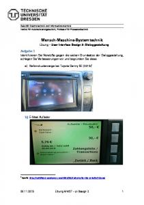
considered at this stage and throughout the remainder of the implementation. These may include specific quantitative requirements such as maximum execution times and error rates, in addition to more qualitative needs such as support for error recovery and flexible working. Figure 5 shows a possible GUI sketch for the Request Book use case derived from the UI elements identified above. It includes representations of workspaces W1, W2 and W4 (an overlaid message). The four functional elements are represented as buttons. At this stage, workspaces are physically sized to fit requirements, and the positioning of both workspaces and functional elements is checked back against task flow needs, as captured within the use case. Other functional elements relating to system operations, e.g. Help, may be added. This process is repeated for each use case and the sketches combined to create a composite user interface prototype.
5
Review and Conclusions
This paper has described two support artefacts - extended tabular use cases and UI element clusters - which provide a bridge between the two central activities within the RUP which relate to user interface design: user interface modelling and user interface prototyping. These artefacts provide support for ‘flow of events’ storyboarding, the clustering of user interface elements and identification of UML boundary classes, and the initial sketching of user interface prototypes.
Library Catalogue System Search Result Request confirmed: check your lending record twice weekly
Title: Human-Computer Interaction Author: Dix, Publisher:Finlay Prentice Hall ISBN: 0132398648
OK
No
Call Number
Location
Status
1.
004.21019 Hum
Campus A
On loan
2.
004.21019 Hum
Campus C
On loan
Select
3.
004.21019 Hum
Campus A
On loan
Select
Select
Enter last date on which book is wanted (mm/dd/yy)
Print
Submit
Cancel
Figure 5: UI sketch for the Request Book use case with confirmation message overlaid There are a number of advantages to using this approach. Tabular use cases: •
Describe essential task sequencing but impose no order on optional activities.
•
Incorporate naturally any “includes” and “extends” use case relationships.
•
Identify exception conditions that have to be handled, including mistakes made by users when entering data.
Extended tabular use cases: •
Provide a flow of events storyboard which is graphical as well as textual. The visual depiction of UI elements makes this easy to understand by all involved in the development process.
•
Are independent of any interface representation style since the elements relate to the content of the application and not a particular “look and feel”.
•
Provide the basis for the generation of the set of transactions for testing the implementation (the extended tabular notation shows all relevant attributes).
UI element clusters: •
Define the distribution and broad layout of UI elements over interaction spaces.
•
Support experimentation with different user interface styles, and the exploration of issues relating to screen layout at a broad level.
•
Make it reasonably straightforward to identify the required UML boundary objects for any specific arrangement of UI elements.
In conclusion, the notation and approach described in this paper provide a systematic approach to moving from a flow of events storyboard that is both graphical and textual to an early prototype of a system. With software support, UI elements could be picked up directly from the third column of extended tabular use cases and arranged to form clusters. Work is proceeding on this. The above process has been followed for a number of applications, including a much fuller version of the library system described in this paper, a university student registration system, and a kiosk-based public information system. The scalability of the artefacts remains to be fully tested. The approach is currently being trialed at Massey University on a postgraduate paper in user interface design.
6
References
COCKBURN, A. (2001) Writing Effective Use Cases, Addison Wesley, Boston. CONSTANTINE, L.L. & LOCKWOOD, L.A.D. (1999): Software for Use: A Practical Guide to Models and
Methods of Usage-Centered Design, Addison-Wesley, Reading, Massachusetts. FOWLER, M. & SCOTT, K. (1997): UML Distilled: Applying the standard object modeling language, Addison-Wesley, Reading, Massachusetts. JACOBSON, I, M. CHRISTERSON, P. JONSSON, & G. OVERGAARD. (1992): Object-Oriented Software Engineering: A Use Case Driven Approach. AddisonWesley Publishing Company, Reading, Massachusetts.
PHILLIPS, C.H.E., KEMP, E.A. & KEK, S.M. (2001): Extending UML use case modelling to support graphical user interface design, Proc. of ASWEC 2001, IEEE, Canberra, Australia, 26-28 August 2001, 48-57. QUATRANI, T. (1998): Visual modeling with Rational Rose and UML, Addison-Wesley, Reading, Massachusetts. RETTIG, M. (1994): ‘Prototyping for Tiny Fingers’, Comms. of the ACM, Vol 37, No 4, 21-28.
JACOBSON I., BOOCH G. & RUMBAUGH J. (1999): The Unified Software Development Process, AddisonWesley, Reading, Massachusetts.
RICHTER, C. (1999): Designing Flexible ObjectOriented Systems with UML, Macmillan, Indianapolis, Indiana.
KOBRYN, C. (1999): UML 2001: A Standardisation Odyssey, Comm. ACM, Vol 42, No 10, 29-37.
RUMBAUGH J., JACOBSON I. & BOOCH G. (1999): The Unified Modeling Language Reference Manual, Addison-Wesley, Reading, Massachusetts.
KRUCHTEN P. (2000): The Rational Unified Process: An Introduction (2nd ed), Addison-Wesley, Reading, Massachusetts. KRUCHTEN P., AHLQVIST S. AND BYLUND S. (2001): User Interface Design in the Rational Unified Process, in Object Modeling and User Interface Design, ed Van Harmelen, Addison-Wesley, Reading, Massachusetts.
UML REVISION TASK FORCE (1999): OMG UML v 1.3 Revision and Recommendations document ad/9906-08, Object Management Group.