Thanksto George Oje- mann and Ken ... References. 1. Ojemann GA, Ojemann J, Lettich E, Berger ... Modayur B, Prothero J, Ojemann G, Maravilla. K, Brinkley J.
Incorporating Constraint-Based Shape Models Into an Interactive System For Functional Brain Mapping Kevin P. Hinshaw, M.S.* and James F. Brinkley, M.D., Ph.D.t Structural Informatics Group * Dept. of Computer Science and Engineering, Box 352350 t Dept. of Biological Structure, Box 357420 University of Washington, Seattle, WA 98195 hinshawfcs.washington.edu, brinkleyfu.washington.edu we are developing an information system for storing, organizing, and sharing functional brain map data, using stimulation mapping as our prototype application.2 This information is gathered during neurosurgery to plan resection for intractable epilepsy. While the patient performs an object naming task, sites on the surface of the brain are stimulated with a mild electrical current. Regions where the stimulation interferes with the naming task are deemed essential for language function, and therefore must be avoided during resection to prevent language impairment. The maps gathered during these surgeries provide a wealth of information about the organization of language function in the brain. Previous work described an interactive system for recovering the 3-D locations of these stimulation sites.3 The system worked by reconstructing the surface of a patient's brain from MR images and allowing the user to mark sites on it, using an intraoperative photo of the exposed cortex for reference. Repeatability results validated the accuracy of this visual mapping approach, but a major drawback was that the surface reconstruction stage required considerable expertise to control. In parallel with this brain mapping project, we have been developing an interactive, shape-based approach to segmentation that promises accurate results and is more intuitive to control than standard methods.4 In this paper we describe a system which integrates the shape-based segmentation method into the brain mapping process. Timing results show that this system is sufficiently fast and robust to be used for the reconstruction and mapping of large numbers of patients.
Through intraoperative electrical stimulation mapping, it is possible to identify sites on the surface of the brain that are essential for language function. Interesting correlations have been found between the distribution of these sites and behavioral traits such as verbal IQ. In previous work, tools were developed for building a reconstruction of a patient's cortical surface and using it to recover coordinates of essential language sites. However, considerable expertise was required to produce good reconstructions. This paper describes an improved version of the mapping procedure, in which segmentation is driven by a 3-D shape model. The model-based approach provides more intuitive control over the system, allowing a trained user to complete a surface reconstruction and mapping in about two hours. This level of performance makes it feasible to gather language maps for a large number of patients, which hopefully will lead to significant new findings about language organization in the brain.
INTRODUCTION Questions about how the human brain works have intrigued both philosophers and scientists for ages, and recent advances in technology have been providing answers rapidly. One such method for learning about how the brain functions is electrical stimulation mapping, which can be used to locate cortical sites that are involved in language processing. Correlations have been shown between the locations of these essential language sites and behavioral indicators such as verbal IQ,1 which raises interesting questions about the connections between variations in cortical anatomy and function. Possible avenues for exploring this relationship abound, especially with the growing availability of fMRI, PET, and other non-invasive methods for gathering functional data. As part of the national Human Brain Project,
1091-8280/98/$5.00 © 1998 AMIA, Inc.
THE MAPPING PIPELINE The protocol for the visualization-based mapping procedure is illustrated in figure 1. Three sets of MR images of the patient's head are acquired. Af-
921
before further processing can take place. Using information that is stored in the image headers about the MR scanner's coordinate space, a single bounding box containing all three series is computed. Each series is then resampled to get a 2563 volume with uniform-sized voxels, yielding three aligned data sets in which a given voxel will correspond to the same location in machine coordinate space. For now, it is assumed that any patient motion between MR scans is negligible. This is not always the case, and in the future we plan to finetune the registration between the three volumes to compensate for patient motion. Segmentation After the three data sets have been aligned, they need to be segmented to find the cortical surface and superficial vessels. Since the objects of interest are known, it is appropriate to use a modelbased approach. Toward this end, we have developed the radial surface model to capture an object's basic shape and range of variation.4 This approach is similar in spirit to deformable models ,5,6 except that the model's constraints are based upon knowledge about the object's shape, rather than a generic local smoothness criterion. Surface features of the cortex vary considerably across the population, so no generalized shape model will be able to capture every detail. However, the overall shape of the brain - its "envelope" - is fairly similar from person to person. Therefore, the radial surface model is used only for finding this envelope. The results of this coarse segmentation can then be used to strip away the scalp and other unwanted structures in the MR data, making it easier to reconstruct a high-resolution cortical surface. The radial surface model. A shape model of the brain's envelope is derived from training examples, which are constructed by defining a reference axis relative to stable landmarks, then extending radials from the axis to the object's surface. These radials are distributed in a series of parallel slices that run perpendicular to the axis. For the brain, we have chosen to use landmarks of the Talairach reference system,7 which is commonly used for registration purposes in neurological studies. For each example surface, ratios of radial lengths are computed to get information about local shape features. Then, for each pair of neighboring radials, the minimum and maximum length ratios occurring in the training set are stored in the model. These ratios act as constraints, spec-
41 "1
4l map sites
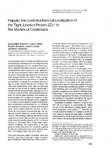
Figure 1: The mapping pipeline. After three sets of MR images are acquired and aligned, they are segmented to reconstruct the cortical surface and its superficial vessels. Stimulation site coordinates are recovered by interactively matching the surface to an intraoperative photo. ter these images have been aligned to one another, an interactive segmentation tool is used to extract the cortical surface and its superficial blood vessels. Finally, using the intraoperative photo for reference, the user marks the positions of stimulation sites on the 3-D reconstruction. The final result is a set of coordinates for the stimulation sites that are in registration with the MR volume. This section describes the stages of the mapping procedure, with emphasis placed on the segmentation stage, which is the most complex and newest component of the system. (See figure 2 for a screen
shot from the system.) Image Acquisition Shortly before a patient's surgery, three image series are acquired using a whole body 1.5 Tesla MR scanner: one is optimized for cortical anatomy, the second for veins, and the third for arteries. These three data sets are transferred from radiology to a local database. Alignment The three sets of MR images have differing orientations and resolutions, so they must be aligned
922
ifying how each radial's length varies relative to its neighbors. When the model is instantiated in a new data set, these constraints can be used to calculate uncertainty intervals for each radial, providing a bounded region within which the object of interest should be located. Model fitting. The user initiates this step by loading a shape model and specifying the landmarks that orient the model. The user also enters one or more initial radials, which are combined with the model's shape constraints to bound the lengths of neighboring radials. A one-dimensional edge detector searches along radials, and each time a likely surface point is found, it can be used to tighten the uncertainty intervals. The system searches for edges and propagates constraints until it can no longer find any good boundary candidates. At this point, it presents its best guess at the fitted model to the user, who can inspect the results and correct individual radials as necessary. Once the model has been fitted to the anatomy data set, it is simple to derive a companion model for use with the aligned venous and arterial data sets. Since the vessels of interest lie just above the surface of the cortex, we slightly lengthen each radial of the fitted model and allow the user to make adjustments as needed. By using the fitted model as a starting point, we avoid the overhead of constraint propagation and edge detection when computing this second model. Volume masking. Once the shape model has been fitted to a particular patient, it is used to mask out the regions outside the cortex. First, a shell is built by marking each voxel that is sufficiently close to a face of the fitted model. Next, a 3-D flood fill is used to mark all of the voxels surrounded by the shell. The unmarked voxels are then removed from the data set, stripping away structures outside of the cortex. Surface extraction. From the masked data set, a final surface can be extracted. A marching cubes algorithm8 is used to construct an isosurface for the cortex. The resulting surface is smoothed by recomputing the vertex normals as a weighted average of the normals in their neighborhood. With the exception of the initial model fitting, the stages of segmentation run very quickly. Thus it is easy for the user to adjust the segmentation results interactively. By looking at the masked volume or the extracted isosurface, it is fairly easy to locate errors in the fitted model. Fixing such errors is straightforward - the user simply ad-
justs radials in the affected region, recomputes the masked data, and extracts a new isosurface. Visual Mapping In the final stage of the mapping process, the reconstructed cortical surface is displayed alongside a digitized version of a photograph taken during the patient's surgery. (See figure 3.) The user establishes the 3-D coordinates for the stimulation sites by dragging numbered tags onto the 3-D surface. The reconstructed veins act as important guides during this process, since the orientation of the patient is often unclear in the photo. RESULTS With any system intended for production use, there are three natural measures of performance: correctness, speed, and ease of use. For the purposes of this project, "correctness" applies primarily to the site locations extracted from the final mapping. Specifically, we want to make sure that the strategy of visually matching the 3-D surface to the photo produces reliable coordinates. Preliminary testing of the previous version of this system showed good repeatability results for a collection of expert and non-expert users.3 The shape-based method produces surfaces that look as good as or better than the earlier reconstructions, so we are confident that the revised system is just as accurate. To gauge the speed of the system, we measured the time required to run a patient through the entire mapping procedure. Table 1 shows the timing results for the various stages of the mapping pipeline, based on having one of the authors process three patients. (The time for image acquisition and transfer has been omitted, since it is independent of the rest of the mapping procedure.) Trials were performed on a Silicon Graphics Indy workstation with a 133MHz R4600 processor and 256 megabytes of memory. On average, it took under two hours to complete a patient's mapping.
STAGE Align Cortex Seg. Vein Seg. Artery Seg. Map Total
PATIENT (h:mm) 2 3 Avg. 0:10 0:09 0:10 0:10 1:07 0:53 1:00 1:00 0:20 0:33 0:14 0:22 0:15 0:08 0:08 0:10 0:10 0:07 0:06 0:08 2:02 1:50 1:38 1:50 1
Table 1: Timings for the mapping pipeline stages.
923
The third performance measure, ease of use, is harder to quantify. One possible indicator is the type of interaction made possible by the shapebased approach. When segmentation errors occur in our current system, the user can quickly locate them, adjust the fitted model in that region, and extract a new surface. From a user's standpoint, this is a significant improvement over our earlier region growing method, which offered little or no local control over the segmentation results. We plan to perform usability studies to see how quickly individuals unfamiliar with the system can learn to use it.
sites could be predicted from fMRI, it would provide a powerful, non-invasive method for planning surgery for these patients. The mapping system we have built is now mature enough to make possible such studies of language organization, and we look forward to the answers that lie ahead.
Acknowledgements This work was sponsored by Human Brain Project grant LM/DC02310, Achievement Rewards for College Scientists (ARCS), and cosponsored by the National Library of Medicine and the National Institute on Deafness and Other Communication Disorders. Thanks to George Ojemann and Ken Maravilla, our collaborators in the departments of Neurosurgery and Radiology. The visual mapping interface and additional support code were developed by Jeff Prothero.
DISCUSSION AND FUTURE WORK Given the inherent problems of any system that involves image segmentation, this interactive mapping system strikes a good balance between automation and practicality. The observations above suggest that it is reasonably fast and robust. It is also important to note that the radial surface model is not limited to segmentation of the brain. We plan to test its usefulness for reconstructing abdominal organs to facilitate radiation treatment planning. Before we do so, the model may need to be generalized to handle structures such as the liver, in which no straight reference axis can be found. One drawback of the system is that the final, high-resolution surfaces are too complex to be manipulated at truly interactive rates. (A typical reconstruction, complete with blood vessels, contains around one million 'triangles, which takes several seconds to render on our current hardware.) For now, this problem is alleviated by allowing the user to experiment with subsampled data until a good segmentation is achieved, and then applying the fitted model to the full-size data set. This is only a temporary solution, though; work needs to be done to simplify the surfaces. Of particular interest are multi-resolution representations, which could be used both to speed the display of complex surfaces and to allow surface editing at multiple levels of detail.9 One exciting prospect is the possibility of expanding the current system to incorporate functional MR imaging. Data could be "painted" onto the surface reconstruction to highlight parts of the brain that are involved in performing certain tasks. In particular, fMRI data for the object naming task could be acquired and mapped onto our reconstructions to study their relationship to stimulation mapping data. If essential language
1.
2.
3.
4.
5. 6.
7. 8.
9.
924
References Ojemann GA, Ojemann J, Lettich E, Berger M. Cortical language localization in left, dominant hemisphere. J. Neurosurgery 71:316-326, 1989. Brinkley JF, Myers LM, Prothero JS, Heil GH, Tsuruda JS, Maravilla KR, Ojemann GA, Rosse C. A structural information framework for brain mapping. in Koslow S, Huerta M, (eds), Neuroinformatics: An Overview of the Human Brain Project, Mahwah, New Jersey, Lawrence Erlbaum, 1997:309-334. Modayur B, Prothero J, Ojemann G, Maravilla K, Brinkley J. Visualization-based mapping of language function in the brain. Neuroimage 6:245-258, 1997. Hinshaw KP, Brinkley JF. Using 3-d shape models to guide segmentation of mr brain images. in AMIA Fall Symposium. 1997:469-473. Kass M, Witkin A, Terzopoulos D. Snakes: Active contour models. Int. J. Comput. Vision 1:321-331, 1987. Davatzikos C, Bryan RN. Using a deformable surface model to obtain a shape representation of the cortex. IEEE Trans. Med. Imag. 15:785795, 1996. Talairach J, Tournoux P. Co-planar stereotactic atlas of the human brain. George Thieme Verlag, Stuttgart, 1988. Lorensen WE, Cline HE. Marching cubes: a high resolution 3d surface construction algorithm. in Computer Graphics. 1987:163-170. Finkelstein A, Salesin DH. Multiresolution curves. in Proc. SIGGRAPH. 1994:261-268.
N.-.E.I.-.-......
I.....,.
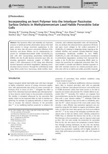
Figure 2: The segmentation interface. Slices through the MR volume are shown at top, with radials from a fitted model displayed on the coronal slice. Bottom left shows an extracted isosurface.
Figure 3: The visual mapping stage. The intraoperative photograph is shown at top left, with the surface reconstruction below. When a site is marked on the 3-D surface, its position is also displayed on MR slices at top right.
925