Dec 4, 2016 - Strategic Center for Science, Technology and Innovation in the ï¬eld of ICT ... RPC Remote Procedure Call ... SaaS Software as a Service.
Aalto University School of Science Degree Programme in Computer Science and Engineering
Sowmya Ravidas
Incorporating Trust in Network Function Virtualization
Master’s Thesis Espoo, October 7, 2016
Supervisor: Advisor:
Prof. Tuomas Aura, Aalto University Dr. Ian Oliver, Nokia Bell Labs
Aalto University School of Science Degree Programme in Computer Science and Engineering
ABSTRACT OF MASTER’S THESIS
Author: Sowmya Ravidas Title: Incorporating Trust in Network Function Virtualization Date: October 7, 2016 Pages: 102 Major: Mobile Computing - Services and Se- Code: T-110 curity Supervisor: Prof. Tuomas Aura, Aalto University Advisor: Dr. Ian Oliver, Nokia Bell Labs This thesis concentrates on ways of establishing trust in a telecommunications cloud environment based on Network Function Virtualization (NFV). Telecommunication network functions can be deployed as software packages known as Virtualized Network Functions (VNF). These VNFs are mission critical network elements such as the Mobility Management Entity (MME) or Home Location Register (HLR), which must be hosted on trusted infrastructure. In such an application, it is important to verify the integrity of both the infrastructure and the VNF in order to reduce the blind trust we place upon it. This leads to challenges, such as finding a balance between resource selection based on trust status and fault tolerance. The goal of this thesis is to understand these challenges in detail, to develop methods to address them, and also to implement a prototype demonstrating these features. We design and implement a trusted telecommunications cloud environment where the infrastructure integrity is verified using trusted computing technologies which use Trusted Platform Module (TPM). We develop a management entity called the Trusted Security Orchestrator (TSecO). This system implements signing of VNF images and VNF-TPM binding to enable VNF integrity checks at launch time and to ensure that VNFs are hosted on the most suitable (trusted) platform available. One particularly interesting problem identified in the experiments is that incorporating trust in NFV may lead to failure situations when the desired trusted resources are not available. We propose a policy-based fault tolerance approach to address the trusted resource selection problem. Altogether, the techniques developed in this thesis are a step towards practical deployment of trusted NFV in the telecommunications cloud. Keywords: Language:
NFV, Telecommunications cloud, Trust, TPM, Orchestration, OpenStack English 2
Acknowledgements This thesis study is conducted at the Security Research Team of Nokia Bell Labs in Espoo, Finland. The work is presented at Aalto University School of Science, as part of the degree requirement for the master’s program in Mobile Computing - Services and Security. The work was supported partly by TEKES, as part of the Cyber Trust program of DIMECC (the Finnish Strategic Center for Science, Technology and Innovation in the field of ICT and Digital Business). I would like to thank my manager, Gabriel Waller, for providing me the opportunity to do master thesis at Nokia Bell Labs. Sincere thanks and gratitude to my advisor, Dr. Ian Oliver; this thesis would not have been possible without his constant guidance and support. Heartfelt thanks to Prof. Tuomas Aura (Aalto University) for supervising my thesis and for providing constructive comments. Many thanks to Ian Oliver, Shankar Lal and Leo Hippel¨ainen for providing their valuable insights on my work. I appreciate the time and effort they took to proof-read this document. Thanks to Dr. Yoan Miche, Dr. Silke Holtmanns, Aapo Kalliola and other members of security research team at Nokia Bell Labs for their constant support. I once again thank Prof. Tuomas Aura, for providing me the opportunity to work as a Research Assistant at the Secure Systems Group of Aalto University during my master studies. It was a good learning experience for me both personally and professionally. Needless to say, this was also a great support to fund my education. Thank you Tuomas, for your continuous help and guidance. Sincere thanks and profound gratitude to Prof. Mario Di Francesco, Prof. Antti Yl¨a-J¨aa¨ski and Eija Kujanp¨a¨a for encouraging me to pursue this degree and for their continued support. 3
Many thanks to Vipin Sir, Abhilash Ettan and other members of am-foss for encouraging me to take risks in life and helping me take steps towards a research career. Special thanks to Sreepriya, Savita and Gayathri for their generous financial aid. I thank Timo and Outi for their kind help during my initial days in Finland. Life here would not have been fun without my friends in Otaniemi and Helsinki. I am grateful for their friendship. Lots of love and gratitude to Amma for supporting me during some of the hardest times in my life. I dedicate this thesis to my parents and sister for believing in my strengths and being with me during the ups and downs of my life.
Espoo, October 7, 2016 Sowmya Ravidas
4
Abbreviations and Acronyms
5G AIK API BIOS BSS BTS CIT CLI CPU CRTM DB DRM EC2 EMS ENodeB ETSI GB GHz HLR HTTP IaaS ID Intel TXT Intel SGX JSON LCP LI LTS MANO
5th Generation Mobile Networks Attestation Identity Key Application Programming Interface Basic Input/Output System Business Support System Base Transceiver Station Cloud Integrity Technology Command Line Interpreter Central Processing Unit Core Root of Trust Measurement Database Digital Rights Management Elastic Compute Cloud Element Management System Evolved Node B European Telecommunications Standards Institute Gigabyte Gigahertz Home Location Register Hypertext Transfer Protocol Infrastructure as a Service Identifier Intel Trusted Execution Technology Intel Software Guard Extensions JavaScript Object Notation Launch Control Policy Lawful Interception Long Term Support Management and Orchestration 5
MB MD5 MLE MME MNO NFV NFVI OS OSS PaaS PC PCR QEMU QoS RAM REST RNG RPC RSA SaaS SHA-1 SHA-256 SLA SP SQL TCB TCG TCP TPM TSecO vCPU vTPM VIM VLR VM VNF XML
Megabyte Message Digest Algorithm 5 Measured Launch Environment Mobility Management Entity Mobile Network Operator Network Function Virtualization Network Function Virtualization Infrastructure Operating System Operations Support System Platform as a Service Personal Computer Platform Configuration Register Quick EMUlator Quality of Service Random Access Memory Representational State Transfer Random Number Generator Remote Procedure Call Rivest, Shamir, & Adleman (Public Key Encryption Technology) Software as a Service Secure Hash Algorithm 1 Secure Hash Algorithm 256 (SHA 2 Family) Service Level Agreement Service Provider Structured Query Language Trusted Computing Base Trusted Computing Group Trusted Computing Pool Trusted Platform Module Trusted Security Orchestrator Virtual Central Processing Unit Virtual Trusted Platform Module Virtualised Infrastructure Manager Visitor Location Register Virtual Machine Virtualized Network Function Extensible Markup Language
6
Contents
Abbreviations and Acronyms
5
1 Introduction
13
1.1
Problem Statement . . . . . . . . . . . . . . . . . . . . . . . . 14
1.2
Contributions . . . . . . . . . . . . . . . . . . . . . . . . . . . 15
1.3
Research Methods . . . . . . . . . . . . . . . . . . . . . . . . . 16
1.4
Structure of the Thesis . . . . . . . . . . . . . . . . . . . . . . 16
2 Background 2.1
17
Cloud Computing and Network Function Virtualization . . . . 17 2.1.1
Network Function Virtualization . . . . . . . . . . . . . 18
2.2
Need for Trust in the Cloud . . . . . . . . . . . . . . . . . . . 20
2.3
Trusted Computing Concepts . . . . . . . . . . . . . . . . . . 22 2.3.1
Trusted Platform Module Architecture . . . . . . . . . 22
2.3.2
Platform Trust Through Boot Time Measurement . . . 24
2.3.3
External Attestation Process . . . . . . . . . . . . . . . 25
2.4
Trusted Cloud . . . . . . . . . . . . . . . . . . . . . . . . . . . 27
2.5
Summary . . . . . . . . . . . . . . . . . . . . . . . . . . . . . 29
7
3 Challenges in Providing Trust in NFV
30
3.1
Terminology . . . . . . . . . . . . . . . . . . . . . . . . . . . . 30
3.2
VNF-VM Assumption . . . . . . . . . . . . . . . . . . . . . . 33
3.3
Requirements . . . . . . . . . . . . . . . . . . . . . . . . . . . 33
3.4
Challenges . . . . . . . . . . . . . . . . . . . . . . . . . . . . . 34
3.5
3.4.1
Platform Trust . . . . . . . . . . . . . . . . . . . . . . 35
3.4.2
VNF Integrity Verification . . . . . . . . . . . . . . . . 36
3.4.3
Launch VNFs on Specific NFVI . . . . . . . . . . . . . 37
3.4.4
Resource Management . . . . . . . . . . . . . . . . . . 38
3.4.5
Fault Tolerance . . . . . . . . . . . . . . . . . . . . . . 40
Summary . . . . . . . . . . . . . . . . . . . . . . . . . . . . . 41
4 Architecture and Design
42
4.1
Modified ETSI NFV Architecture . . . . . . . . . . . . . . . . 42
4.2
Trusted Security Orchestrator . . . . . . . . . . . . . . . . . . 43
4.3
Signing Mechanism . . . . . . . . . . . . . . . . . . . . . . . . 44
4.4
VNF-TPM Binding Mechanism . . . . . . . . . . . . . . . . . 46
4.5
Resource Selection . . . . . . . . . . . . . . . . . . . . . . . . 48 4.5.1
Modified Filter Scheduler in OpenStack . . . . . . . . . 48
4.5.2
Modified OpenStack’s Architecture: Launch of VNF Instance . . . . . . . . . . . . . . . . . 50
4.6
Fault Tolerance Based on Policy Mechanism . . . . . . . . . . . . . . . . . . . . . . . . . 53
4.7
Trust Relationship Between Entities . . . . . . . . . . . . . . . 55
4.8
Use Cases . . . . . . . . . . . . . . . . . . . . . . . . . . . . . 57
4.9
Summary . . . . . . . . . . . . . . . . . . . . . . . . . . . . . 58 8
5 Implementation
59
5.1
Building a Trusted Cloud
5.2
Implementation Set-up . . . . . . . . . . . . . . . . . . . . . . 61
5.3
Implementation of Custom Filters . . . . . . . . . . . . . . . . 63
5.4
. . . . . . . . . . . . . . . . . . . . 59
5.3.1
Signature Filter . . . . . . . . . . . . . . . . . . . . . . 64
5.3.2
VNF-TPM Binding Filter . . . . . . . . . . . . . . . . 65
Implementation of Trusted Security Orchestrator . . . . . . . . . . . . . . . . . . . . . . . . . . . . 66 5.4.1
Verifying Integrity of VNFs Through Signing Mechanisms . . . . . . . . . . . . . . . . . . . 67
5.4.2
Binding VNFs to TPM . . . . . . . . . . . . . . . . . . 67
5.5
Performance Evaluation of Signing and VNF-TPM binding . . 72
5.6
Summary . . . . . . . . . . . . . . . . . . . . . . . . . . . . . 76
6 Discussion
77
7 Conclusions
81
A
89 A.1 Enabling tboot . . . . . . . . . . . . . . . . . . . . . . . . . . 89 A.2 OpenStack Hypervisor Summary . . . . . . . . . . . . . . . . 90 A.3 TSecO Modules Code Snippets . . . . . . . . . . . . . . . . . 92 A.3.1 Log Function . . . . . . . . . . . . . . . . . . . . . . . 92 A.3.2 Signature Verification Function . . . . . . . . . . . . . 92 A.3.3 PCR Function . . . . . . . . . . . . . . . . . . . . . . . 94 A.3.4 VNF-TPM Binding Function . . . . . . . . . . . . . . 95 A.4 Creating a Filter . . . . . . . . . . . . . . . . . . . . . . . . . 98 9
A.4.1 Modified Base Host Filter . . . . . . . . . . . . . . . . 99 A.4.2 Signing Filter . . . . . . . . . . . . . . . . . . . . . . . 100 A.4.3 VNF-TPM Binding Filter . . . . . . . . . . . . . . . . 101 A.5 MongoDB and Policy Insertion . . . . . . . . . . . . . . . . . 102
10
List of Figures
2.1
ETSI NFV Reference Architecture
. . . . . . . . . . . . . . . 19
2.2
Trusted Platform Module Architecture . . . . . . . . . . . . . 23
2.3
Chain of Trust
2.4
Remote Attestation . . . . . . . . . . . . . . . . . . . . . . . . 26
2.5
Attestation Service Communication Flow . . . . . . . . . . . . 26
3.1
Assumption . . . . . . . . . . . . . . . . . . . . . . . . . . . . 33
3.2
NFVI Time Scale . . . . . . . . . . . . . . . . . . . . . . . . . 35
3.3
Trusted Resource Selection . . . . . . . . . . . . . . . . . . . . 39
4.1
High Level System Architecture . . . . . . . . . . . . . . . . . 43
4.2
Trusted Security Orchestrator . . . . . . . . . . . . . . . . . . 44
4.3
Creating a Signature File . . . . . . . . . . . . . . . . . . . . . 45
4.4
Verification of Signature . . . . . . . . . . . . . . . . . . . . . 45
4.5
Policy for Binding . . . . . . . . . . . . . . . . . . . . . . . . . 46
4.6
VNF-TPM Binding Process . . . . . . . . . . . . . . . . . . . 47
4.7
OpenStack Filter Scheduler . . . . . . . . . . . . . . . . . . . 49
4.8
OpenStack Resource Selection Process . . . . . . . . . . . . . 49
. . . . . . . . . . . . . . . . . . . . . . . . . . 24
11
4.9
Provisioning VNFs: Modified Architecture . . . . . . . . . . . 51
4.10 Policy Lattice Based on Length of Policies . . . . . . . . . . . 54 4.11 Trust Chain . . . . . . . . . . . . . . . . . . . . . . . . . . . . 55 5.1
Cloud Infrastructure . . . . . . . . . . . . . . . . . . . . . . . 59
5.2
PCR Values . . . . . . . . . . . . . . . . . . . . . . . . . . . . 61
5.3
Implementation Set-up . . . . . . . . . . . . . . . . . . . . . . 62
5.4
Image Metadata . . . . . . . . . . . . . . . . . . . . . . . . . . 64
5.5
Sequence Diagram of Signing Process . . . . . . . . . . . . . . 68
5.6
VNF-TPM Binding Process . . . . . . . . . . . . . . . . . . . 69
5.7
Response from Attestation Server . . . . . . . . . . . . . . . . 70
5.8
Sequence Diagram of Binding Process . . . . . . . . . . . . . . 71
5.9
Execution Time of Filters . . . . . . . . . . . . . . . . . . . . 73
5.10 Normal Launch Time Vs Launch Time with Signature Verification . . . . . . . . . . . . . . . . . . . . . . . . . . . . . . . 74 5.11 Launch time with Signature Verification Using Different Hash Functions . . . . . . . . . . . . . . . . . . . . . . . . . . . . . 75 A.1 OpenStack Hypervisor Summary . . . . . . . . . . . . . . . . 90 A.2 Intel Attestation Server Portal . . . . . . . . . . . . . . . . . . 90 A.3 VNF Image Metadata . . . . . . . . . . . . . . . . . . . . . . 91 A.4 VNF Integrity Output . . . . . . . . . . . . . . . . . . . . . . 93 A.5 VNF-TPM Binding Output . . . . . . . . . . . . . . . . . . . 97
12
Chapter 1
Introduction Cloud computing is one of the fastest growing technologies. Services such as email, servers, storage and network components are being deployed in the cloud environment, due to its scalability, elasticity and low cost [34]. In this study, the focus is on the Infrastructure as a Service (IaaS) model of cloud computing, in which the customers are provided with storage, network and processing capacity. However, the underlying architecture is controlled by the infrastructure providers [34]. In such scenarios, it is not possible to completely trust the infrastructure providers and the servers where our data resides. The notion of trust has been considered in cloud infrastructure standards such as ETSI’s Network Functions Virtualization (NFV) [6], where telecommunication network functions can be deployed as software in the form of virtualized network functions (VNFs). In such a critical application, it is of high priority to launch network functions in a trusted environment. The Trusted Computing Group (TCG)1 has developed a specification that aims to enhance security and trust of the computer platforms [2]. This enhancement is possible with the introduction of Trusted Platform Module (TPM), which is an embedded chip capable of storing keys, certificates and other confidential data and protecting from the software running on the machine. Furthermore, TPM along with other software mechanisms such as launch control policies (LCP) and external attestation can perform integrity checks on the infrastructure and the customer-selected platform, and also notify the administrator when any unauthorized modifications have been made 1
https://www.trustedcomputinggroup.org
13
CHAPTER 1. INTRODUCTION
14
to it. Such hardware-software co-design based integrity verification mechanisms harden the system against software attacks. Integrating trusted computing technologies with the cloud infrastructure has been studied in [9], [35], [52] and [38]. Intel processors incorporate Trusted Execution Technology (Intel TXT) [22] that provides a hardware root of trust by verifying the integrity of critical components, such as the BIOS module, host OS and the hypervisor, and storing the results in TPM. This can be used in NFV where the service providers need to know the trust level of the computing infrastructure before launching the VNFs. Hence, it is important to check the integrity of the cloud platform after boot. Existing external attestation technologies such as the Intel Cloud Integrity Technology (Intel CIT)2 performs the remote verification of the platform and verifies if the platform is trusted or not based on known good values. However, in an NFV environment, we are required to provide more than boot-time trust and external attestation. In addition to platform integrity, verifying the integrity of the VNFs and launching the VNFs on most suitable hardware are crucial for establishing trust in NFV. Also, the infrastructure provider is required to maintain the service level agreements (SLAs) with the user or service providers. The SLAs explain the responsibilities of the infrastructure provider on the quality of service (QoS). In order to meet the desired QoS in NFV, we have to minimize the failures in launching the VNFs. Hence, it is also necessary to consider the aspects of fault tolerance and resource management. In this thesis, trust refers to knowing the state of the system. This means that, even if the system is in a bad state, we still trust that it is in a bad state, rather than in an unknown state.
1.1
Problem Statement
The VNF integrity check during the launch time is a crucial factor for the successful deployment of VNFs. An image is selected to launch the VNFs; however, the integrity of this image is usually not verified. It is possible to inject malware into VNF images within a few seconds. The existing mechanisms do not consider insider attackers as potential threats. Hence, there is a need for external verification and monitoring of VNFs. 2
http://download.intel.com/support/sftw/ds/cit/sb/trust attestation server 2 0 product guidev2.pdf
CHAPTER 1. INTRODUCTION
15
In a telco cloud environment, the service providers would require to launch the VNFs in a platform with specific configurations. While the TPM can measure the system components, there are no existing methods that bind the VNFs to a specific platform. Also, there are limited works that consider trust failure when using trusted technologies in cloud-based environments. For example, there can be scenarios where there are no trusted hosts available, leading to a resource management problem. In such cases, there is a need to consider fault tolerance mechanism to handle the unavailability of trusted hosts.
1.2
Contributions
In this thesis, we address the problem of integrity verification of VNF images and binding VNFs to the TPM. We also address the resource management and fault tolerance issues in an NFV environment. Our contributions are as follows: 1. Implemented a trusted telecommunication cloud using trusted computing technologies. 2. Designed and implemented VNF integrity check using an external signing mechanism, which is a method for verifying the VNF image integrity at the launch time. 3. Designed and implemented VNF-TPM binding mechanism using a policybased approach that solves the problem of whether the VNF can be launched on the selected host. 4. Implemented the Trusted Security Orchestrator, which is a management entity deployed in the management and orchestration stack of NFV. This entity performs the VNF integrity check, VNF-TPM binding mechanism and keeps audit logs of hypervisor requests. 5. Investigated on the resource management problem in a trusted telecommunication cloud. 6. Proposed a policy-based fault-tolerance mechanism to handle the unavailability of trusted resources.
CHAPTER 1. INTRODUCTION
1.3
16
Research Methods
In this thesis, the experimental research method [18] has been used where we devised solutions to the identified problems and evaluated them. Existing trusted computing technologies are used to build new solutions such as the external signing of VNF images and the VNF-TPM binding mechanism. We made new observations on the problem of trust and resource management. Also, a solution for solving resource management problems through a faulttolerance approach is proposed, which leads to new research directions.
1.4
Structure of the Thesis
The rest of the thesis is structured as follows. Chapter 2 gives an overview of trust in telecommunication cloud environment, trusted computing technologies and discussions on the existing work in this area. In Chapter 3, we highlight the challenges of incorporating trust in NFV. The system design and architecture are detailed in Chapter 4, and Chapter 5 provides the implementation details and performance evaluation. Chapter 6 discusses the strengths and limitations of our work, and Chapter 7 concludes the report.
Chapter 2
Background This chapter provides an overview of cloud computing and the notion of trust in a cloud infrastructure with a focus on telecommunication cloud. We explain the concepts of trusted computing, Network Function Virtualization (NFV) and the current research on enabling trust in NFV. Throughout this thesis, we refer telecommunication cloud as telco cloud.
2.1
Cloud Computing and Network Function Virtualization
Nowadays, we can find most of the applications and services are being deployed in a cloud environment. In addition to fast scalability, cloud provides a pay as you go model that makes it more convenient for businesses to use [34]. The services provided by the cloud are categorized into the following three models [16]. 1. Software as a Service (SaaS) The cloud providers release their services that can be accessed over the Internet. Examples of such services are Gmail and Google docs. 2. Platform as a Service (PaaS)
17
CHAPTER 2. BACKGROUND
18
In a PaaS model, the development platform is made available to the users, who can develop cloud-based services. One such example is Google App Engine. 3. Infrastructure as a Service (IaaS) In an IaaS model, the infrastructure that includes the processing, storage, network and other resources are provided to the users. Amazon’s EC2 is an example of an IaaS model. This eliminates the need to construct and maintain a data center. With the reduced capital and operational expenses, there is a trend towards companies deploying their operations entirely to a cloud-based environment. There are various categories of deployments of the cloud. Often it is categorized as either public cloud or private cloud [10]. When the services are provided to the general public, it is called as public cloud, such as Amazon EC2. When the services are available only within an organization and not to general public, then this is called as a private cloud, typically used by large organizations. There are also other types of deployment such as the community cloud and hybrid cloud [16]. In a community cloud, different organizations maintain and share a cloud environment. Hybrid cloud can be a combination of any of public, private or community cloud. Another category of cloud is the telco cloud, where the focus is on telecom applications that can be deployed in a cloud [20]. Some of the benefits of moving telecom operations to cloud include virtualizing data center infrastructure for on-demand hosting, delivering telecom functions as SaaS applications and providing storage on demand [11]. In this thesis, we focus on the SaaS and IaaS models of a telco cloud. In such models, the aim is to deploy telecommunication operations by virtualizing the software and network functions.
2.1.1
Network Function Virtualization
In a telco cloud environment, network functions such as mobility management entity (MME), base transceiver station (BTS), home location register (HLR) and visitor location register (VLR), form the basic building blocks and provide the functionality required for any communication services. Adding
CHAPTER 2. BACKGROUND
19
new services in network functions require purchasing new hardware equipments or physical installation and commissioning of them. Also, software upgrade becomes complicated due the physical location of hardware equipments such as cell towers. Network functions can take a long time to activate or upgrade the system and makes the process difficult, especially in scenarios where more devices get connected to each other1 . Hence, there is a need for an easier way to deploy these network functions. Network Function Virtualization helps to solve this problem by reducing the need to rely on hardware and thereby reducing the overall cost. In NFV, network functions and some parts of the infrastructure are implemented as software or, in other words, they use virtualized resources. Traditional cloud combined with NFV provides an ideal environment for the next generation telco cloud. The ETSI NFV Reference architecture [5] is shown in Figure 2.1. The
Figure 2.1: ETSI NFV Reference Architecture
NFV architecture consists of Network Function Virtualization Infrastructure (NFVI), which consists of the hardware and virtual resources. We deploy our VNFs on the NFVI. There is also a Management and Orchestration ele1
https://www.ericsson.com/res/docs/whitepapers/network-functions-virtualizationand-software-management.pdf
CHAPTER 2. BACKGROUND
20
ment that performs the resource allocations in NFVI, life cycle management of VNFs and overall orchestration. The functionality of these components is explained below. The Network Function Virtualization Infrastructure (NFVI) consists of all the hardware resources such as compute, storage and network elements. The virtualization layer creates a hardware abstraction of the resources below. Above this, we have the virtual compute element, virtual storage element and virtual network element. We see that NFVI consists of the hardware, virtualization layer as well as the virtual resources that are necessary to launch a VNF. Above the NFVI, we have the Virtualized Network Functions (VNF) which are basically software packages that can implement the network functions (such as routers and firewalls) using the infrastructure provided by the NFVI. Each VNF is connected to an Element Management System (EMS) that manages the operations of the VNF. The OSS and BSS refer to the operational and the business support systems of a mobile network operator (MNO). The Management and Orchestration block consists of the Virtualized Infrastructure Manager (VIM), VNF Managers and the Orchestrator. The VIM manages and controls the interaction of NFVI to the VNFs. It performs the resource management and also analyses the performance of NFVI. The VNF Managers help the VNFs to instantiate, update, scale and terminate, and they also perform other critical functions that are necessary for the entire VNF life cycle. The Orchestrator performs global management of NFVI and policy management for the network services.
2.2
Need for Trust in the Cloud
With the advancements in the area of cloud and NFV, enterprises have considered deploying their services on the cloud. However, one of the major challenges they face is the lack of trust. The notion of trust is an important factor to consider, especially when we run mission critical components on the cloud. In [49], the authors have considered various definitions of trust as a social concept as well as in a digital environment. Ko et al. [28] define trust in cloud
CHAPTER 2. BACKGROUND
21
as the confidence that we place in the cloud. In an IaaS model, the word trust can be associated with the confidence that we place on infrastructure providers i.e. the belief that our data is protected and our services in cloud are working in an expected manner. In such scenarios, trust often refers to the integrity of the system. In all the service models of cloud, users do not have control over the infrastructure and they are often required to trust the infrastructure providers [41]. Chow et al. [12] emphasize the lack of control of data in the cloud, which is one of reasons why some enterprises do not move their operations into the cloud. Also, organizations that require data protection policies are required to know how the data is managed and also to know if there have been any changes made to it [37]. Hence, transparency of data control and security guarantees are crucial for placing trust in the cloud. With the growing use of virtualization technologies, the users and the service providers have to trust the cloud providers. Zhang et al. [53] consider cloud security as one of the main topic areas of research and trusting the infrastructure as one of the important challenges faced by the cloud users. The authors state that the infrastructure provider must provide confidentiality and auditability to the service provider to ensure secure data transfer and integrity of the data. The authors further stress on the need for a trusted hardware and trusted virtualization layer. In [41], the authors highlight the set of attacks possible in a cloud environment. For example, they explain the possibility of an attacker to retrieve confidential information such as passwords, certificates, private keys and other critical information from the cloud. Their attacks mostly deal with attacking the VM such as capturing VM snapshots, analyzing memory dump of VM, attacks performed on VM migration. The authors also list the possibility of circumventing the current protections in the cloud environment; however, they do not propose a solution or mitigation for the specified attacks. In [15], the authors explain the challenges of IaaS such as the level of trust on the infrastructure provider, data control, data integrity verification and VM integrity. The paper also provides a method to secure virtual machine images by encrypting it in the client side. However, the proposed method does not enhance trust in infrastructure providers. Dawoud et al. [14] provide a list of challenges associated with trust in IaaS and also lists the possible solutions to address these challenges. According to the authors, one of the critical components in an IaaS is the Service Level
CHAPTER 2. BACKGROUND
22
Agreements (SLA). SLAs detail the benefits and responsibilities of the service provider and infrastructure provider. The IaaS providers are not supposed to violate the SLAs or the requirements of the service providers. This is crucial in scenarios, such as, lawful interception where there is a legal requirement to launch the services in a specific geographic location. In such scenarios, it is important to have a clear list of policies concerning the SLAs, especially in cases of VM migration and evacuation. Preserving SLAs is a critical component in a telco cloud environment as well. The aspect of trust has also been considered in other cloud infrastructures such as in mobile cloud [25]. Survey papers focusing on cloud security such as [14], [48], [19], [12] and [21], have discussed the aspect of trust with respect to IaaS and the necessity to introduce trusted computing technologies in the infrastructure. Yang et al [51] discuss about security in NFV and have consider trust management as a security challenge. In [53], the authors highlight the necessity to introduce TPM to the hardware and also motivates the need to have multiple layers of trust in the architecture. It is evident from the above sources that trust is an important factor to be considered in a cloud environment and especially for IaaS model. A solution specified in the above papers is to use trusted computing technologies, which provides a method to enable trust by verifying the integrity of the platform.
2.3
Trusted Computing Concepts
Trusted Computing defines a set of technologies that can provide trusted platforms [43], and hence, reducing the level of blind trust the users have on the cloud infrastructure providers. Such technologies leverage the use of the Trusted Platform Module (TPM) chip in its hardware layer. In this section, we will look into the TPM architecture and explain how such technologies provide a trusted platform.
2.3.1
Trusted Platform Module Architecture
Trusted Platform Module2 (TPM) is a micro-controller that is capable of storing keys, passwords, certificates and other confidential data. TPM can 2
http://www.trustedcomputinggroup.org/trusted-platform-module-tpm-summary/
CHAPTER 2. BACKGROUND
23
Figure 2.2: Trusted Platform Module Architecture
be used for secure storage, to verify the integrity of the platform and also disk encryption. TPM is often embedded onto the motherboard of servers or PCs. The basic components of a TPM version 1.2 [1] are shown in Figure 2.2. The I/O Buffer is the area between the host system and the TPM. The system sends the request and retrieves the response through this buffer. The non-volatile memory stores the state associated with the TPM. The TPM checks if the value it stores is same as that of the values in the non-volatile storage. This component must be in a protected area and should have restricted access. TPM uses random numbers while creating signatures, nonces and also in keys. The random number generator has components such as entropy functions, mixing functions and state registers to ensure the randomness. The Platform Configuration Registers (PCRs) are registers that contain the measurements of various components such as BIOS, hypervisor and operating system. Measurements are cryptographic hashes of these components and are stored in PCRs. Each TPM has 24 PCR registers numbered 0-23. Each PCR register has the capacity to store 20 bytes in it. PCR Registers 0-7 store the measurement values of ROM and the BIOS. PCR 8-16 stores the measurement values of the OS-related files. PCR 18 stores the value of the hypervisor and PCR 22 stores the measurement of a Geo-location trust certificate and related entities. The SHA-1 Engine performs the hash function used by the TPM to take the
CHAPTER 2. BACKGROUND
24
hash of the measured values. In this scenario, we use the SHA-1 algorithm. The Attestation Identity Key (AIK) or simply known as the Attestation Key is generally used for the signing procedures. The key generation component produces two keys. One is the ordinary key that is generated by the RNG. The other is the primary key that is generated using the seed value. The Program Code executes the TPM commands and also ensures the integrity of PCRs. The RSA Engine performs the 2048 bit RSA encryption and decryption operations.
2.3.2
Platform Trust Through Boot Time Measurement
Platform trust during the boot time can be achieved with the use of TPM. As mentioned previously, the PCR registers in TPM store cryptographic hashes of software components such as the BIOS, boot loader, OS and hypervisor. In this section, we explain this process using the Intel TXT terminology. Intel TXT is a hardware technology from Intel which aims to provide root of trust and verify the integrity of platform [22].
Figure 2.3: Chain of Trust
The Trusted Computing Base (TCB) refers to the set of platform specific components which are crucial for measuring the trust level of the system.
CHAPTER 2. BACKGROUND
25
TXT provides a Measured Launch Environment (MLE), which verifies the measurement values of these components based on known good values. The Core root of trust Measurement (CRTM) is the first set of code executed during boot. During the initial boot, the CRTM measures BIOS and writes the hash to the PCRs 0-4. Then it transfers the control to BIOS. BIOS measures the boot loader, writes to PCRs 5-7 and transfers control to the boot loader. The boot loader measures the operating system, writes to PCRs 8-15 and gives control to the OS. The OS would perform this operation on the hypervisor, and so on forming a chain of trust [29], [46]. This is as depicted in Figure 2.3. During a trusted boot, these components are measured and verified against known good values. If this chain is broken, then the system is halted or is started according to the launch control policies (LCP) specified by the admin. Launch Control Policies are the list of policies that verifies if the system meets the required criteria and further decides if the system has to be booted or not. This is a static root of trust measurement. If there has been any changes in measurement values after establishing the trust, due to new components or upgrades, then the TPM has to be reset.
2.3.3
External Attestation Process
Verifying the platform trust is achieved during the system boot. However, in a telco cloud environment, after the NFVI boot the service provider may want to verify the platform configurations before launching its VNFs. In such scenarios, we require an external attestation mechanism that can prove the trust of a remote platform. External attestation is a process where a verifier can check the integrity of a remote machine with the help of an attestation server. The verifier can query the attestation service to know if a host is trusted. The attestation service queries the TPM of the selected host and fetches the PCR values. The attestation server compares them against known good values and informs the verifier whether the host is trusted or not, as shown in Figure 2.4. This mechanism is successful only for hosts that have TPM configured in it. The communication and key exchange between the verifier, attestation service and TPM are as shown in Figure 2.5 [33].
CHAPTER 2. BACKGROUND
Figure 2.4: Remote Attestation
Figure 2.5: Attestation Service Communication Flow
26
CHAPTER 2. BACKGROUND
27
1. Step 1: The verifier sends a 160 bit nonce to the attestation server. 2. Step 2: The Attestation server sends this nonce to the TPM of the machine whose integrity is to be verified. 3. Step 3: The TPM responds to the attestation server with a TPM quote which includes the PCR values and the quote that is signed by the attestation identity key. 4. Step 4: The attestation server also retrieves the current measurement from the measurement list. 5. Step 5: It further sends the quote and the measurement list to the verifier. The verifier decrypts the quote with the public attestation identity key. It checks if the nonce is the same as the one that it had sent to the attestation server. Further, it compares the PCR values to the measurement list and decides whether it can trust the system or not. Intel’s Cloud Integrity Technology [7] is an example attestation server which can be used in cloud platforms.
2.4
Trusted Cloud
We can build a trusted NFV by enabling a TPM in the NFVI layer. A trusted NFV can enhance the trust level of the platform and also enhance the confidence of telecom operators to deploy their network functions as VNFs. In this section, we discuss some of the ongoing research on integrating TPM with a NFV or cloud infrastructure. In [27], authors explain the challenges and the requirements that emerging technologies need to satisfy in order to establish trust in cloud. These requirements include platform integrity and remote access control. Additionally, they have also considered certification of the cloud and a strong security policy as some of the other requirements for placing trust in cloud. Abbadi et al. [8] discuss the issue of data control by IaaS providers and the need for trust mechanism between the users and the providers. In their paper, a trust framework is presented for cloud. In this framework, the physical layer consists of TPM and it communicates with the control agent
CHAPTER 2. BACKGROUND
28
so as to monitor the operational status of the cloud. The authors aim to create a chain of trust between the user and the cloud provider, although, it seems to be an extended version of trust establishment based on remote attestation process. In [45], the authors present a mechanism to verify the integrity of a VM. This is achieved by introducing a cloud verifier component that attests the VM, and the process involves key exchange between the user and the cloud verifier. Further, they devise a functionality to encrypt the image and decrypt it when a request arrives. The authors claim that this gives enough proof to the user that their VM is launched in a trusted hardware. However, verifying the integrity of VM images during launch time is not considered. Also, a strong evaluation of this mechanism is missing from their paper. Previously, we have discussed SLAs and the need to protect them. A common SLA between the user and the cloud provider is to enforce data protection by defining geographic boundaries to the data as mentioned in [26]. In such conditions, the VM migration or evacuation might not be possible if it violates the geographic policy specified by the user. However, in a cloud environment with many VMs running, the IaaS providers do not provide any verification mechanism that the VMs are actually functioning according to the policies specified. In [26], the authors further discuss engineering a middle-ware system that can assert the integrity of the components and to verify if geographic trust is maintained. This is achieved by introducing TPM in the hardware and maintaining a hardware root of trust. The paper discusses more challenges associated with ensuring geographic trust. Yan et al. [50], presented a trust framework for network function virtualization and 5G security. The authors use trusted computing technologies in the NFVI layer, so as to preserve trust in the platform. Further, they have a trust management middle layer and trust functions running on top of NFVI. However, they have not evaluated the framework with the requirements they have specified and also an implementation of this framework is missing. In [37], authors have focused on implementing trust in cloud by using trusted computing technologies. The proposed system’s functionality is similar to traditional trusted boot mechanism and remote attestation. The authors have included the aspect of logging in-order to monitor and detect tampering. There have been efforts on virtualizing the TPM, commonly known as vTPM [39], [44]. vTPM is helpful during migration where we can migrate the vTPM along with the VM. This guarantees a flexible migration process and provides
CHAPTER 2. BACKGROUND
29
an easier way to do an integrity check after migration. However, this process is complicated. vTPM has to measure components in the new platform, which results in a failure as vTPM would contain the old cryptographic keys or associated data against the specified VM [42]. There has been significant work done on establishing trust in cloud through trusted computing technologies. Technologies such as Intel TXT [22] and Intel’s Software Guard Extensions (Intel SGX)3 are being used in real world cloud scenarios. However, it is still insufficient to solve the challenges in a telco cloud environment. In this thesis, we aim to establish trust in NFV and address the challenges associated with it.
2.5
Summary
In this Chapter, we have explained the concepts of cloud computing and NFV. We explored the need for placing trust in such environments. Further, we have discussed the existing trusted computing technologies and their functionality. In the last section, we have looked into the existing research that combines trusted computing in cloud-based systems.
3
https://software.intel.com/en-us/sgx
Chapter 3
Challenges in Providing Trust in NFV In this chapter, we explain the challenges in providing trust in NFV. The challenges include providing platform trust for NFVI, developing VNF integrity verification mechanisms, resource management in NFV and fault tolerance. Firstly, we explain the terminology associated with trust and our assumptions. Next, we look into these challenges in detail.
3.1
Terminology
In this section, we introduce and clarify the terminology associated with NFVI, VNF and trust. NFVI States: 1. NFVI Boot This refers to the boot process of a single NFVI host. In trusted environment, the NFVI integrity is verified during this stage. 2. NFVI Run This refers to the state of NFVI where it is functional and is capable to launch a VNF. To verify the trust status of an NFVI element during its run time, we can use the remote attestation mechanisms.
30
CHAPTER 3. CHALLENGES IN PROVIDING TRUST IN NFV
31
3. NFVI Terminate This state occurs when the NFVI encounters a shut down due to crash or for maintenance purposes. When a trusted NFVI hosting sensitive workload encounters this state, all the workload needs to be migrated to another trusted platform residing in trusted compute pool. 4. NFVI Crash The NFVI can move to a crash state when any of its components stops functioning correctly. VNF States: 1. VNF Launch This state refers to the processing of request to launch the VNFs. A host is selected during this phase that match the requirements of a VNF. 2. VNF Boot This refers to the boot process of individual VNFs. A VNF can also be booted in a trusted way by verifying its integrity. 3. VNF Run This refers to the running state of a VNF where the network functions start to operate. 4. VNF Suspend VNF can enter into a suspend state when we want to save the current state of the VNF and resume during a later point in time. When a VNF is suspended, its virtual storage disk should be encrypted in order to avoid sensitive data leakage. The encryption and decryption keys can be secured by storing them in TPM. 5. VNF Snapshot A snapshot is a VNF system state at a particular time. A snapshot of a VNF can be loaded as a new image. 6. VNF Migration This process involves the movement of running VNFs from one NFVI to another including its memory, compute and storage. 7. VNF Evacuation VNF evacuation is the process of forced migration. This operation is performed during emergency situations such as NFVI crash.
CHAPTER 3. CHALLENGES IN PROVIDING TRUST IN NFV
32
8. VNF Crash A VNF can crash due to failure in VNF components or the NFVI. VNF crashes can be mitigated using fail-over or backup mechanisms but the data associated with crashed VNF needs to be securely deleted or evacuated in order to avoid unauthorized access to it. Terminology Associated with Trust: We now define the terminology associated with the notion of trust depending on the platform and location of NFVI. 1. Platform Trust The term platform trust implies the state of NFVI where the integrity of all critical components such as BIOS, OS and hypervisor is preserved. For VNFs that require only platform trust, it is free to start, migrate or evacuate on a trusted machine as long as the integrity of platform components is preserved. 2. Geographic Trust Geographic trust implies the geo-location trust of NFVI. This is critical in cases of VNFs such as Lawful Interception (LI), where the VNFs are expected to be launched in specified geographic location. In such scenarios, the VNFs may be restricted to migrate or evacuate to other geographic locations that are not mentioned in the service level agreements. In a telco cloud environment, the service providers may have to run critical VNFs that impose geographic restrictions. In such scenarios, we require both the platform trust as well as geographic trust. In such conditions, the VNFs can be migrated or evacuated to another trusted machine but in the same geographic area. We define trust as a process of ensuring that the integrity of the system is preserved or maintained. Integrity of platform components affect the placement of VNFs. In this thesis, we introduce two new terms, the hard trust and soft trust. If the VNFs require hard trust, it implies that the VNFs can be launched only if all the components of the system are trusted. Such policies of trust can lead to difficulties during migration and evacuation when there are no trusted resources and this eventually leads to deliberate killing of the VNFs. However, soft trust allows mitigations and the VNFs can be
CHAPTER 3. CHALLENGES IN PROVIDING TRUST IN NFV
33
launched irrespective of trusted hosts and later have the flexibility to migrate to more suitable trusted host. Such mechanisms preserve SLAs and are easier to perform migration and evacuation of the VNFs.
3.2
VNF-VM Assumption
VNFs are network functions such as MME, HLR and VLR, that run on a virtual machine. We can run multiple VNFs on a single VM or single VNF on multiple VMs as well. The relationship between a VNF and VM is manyto-many.
Figure 3.1: Assumption
In this thesis, we assume the relationship between VNF and VM is one-toone for simplicity reasons. This assumption is reasonable, as many of the practical deployments often consider VNFs as traditional VMs.
3.3
Requirements
In this section, we list the requirements of trust in NFV. The ETSI report on security and trust guidance [6], mentions about NFV high level trust goals. Some of these are: 1. Establishing trust in the platform or NFVI. The goal is to verify that the platform is in an expected state. 2. Establishing trust in software, policies and processes. This includes VNFs, MANO elements and other components in NFV. Establishing trust in each of these components is essential; for example, a tampered VNF can affect other VNFs.
CHAPTER 3. CHALLENGES IN PROVIDING TRUST IN NFV
34
3. Supplying guidance for operational environment such as MANO and EMS, that is critical in decision making. 4. Defining trust relationships between virtualization resources for trust life-cycle management. In the ETSI report they have also stressed on the measures that need to be taken during a trust failure. Some of the options they have considered are: 5. Inform the failure to another trusted entity 6. Increasing the logging levels 7. Reducing operational parameters 8. Other options include to work normal, cease the operation or destroy Consolidating the above goals, we derive the following requirements to establish trust in NFV. 1. The NFVI must be trusted and a mechanism is needed to verify this. 2. NFVI must ensure that the quality of service (QoS) of VNFs are met. This implies that NFVI should aim to preserve SLAs and minimize the occurrence of failure. 3. NFVI should verify the trust status of VNFs before launching. 4. An external needs to audit the actions of NFVI
3.4
Challenges
NFV is a relatively new concept and there are numerous challenges associated with it. However, only a few existing literatures have discussed on the challenges of incorporating trust in NFV. The ETSI white paper [4] on NFV details the challenges associated with NFV. They consider security and resilience as some of the challenges, however, they do not explicitly state trust as a challenge. Similarly in [23], the
CHAPTER 3. CHALLENGES IN PROVIDING TRUST IN NFV
35
authors consider only security as one of the challenges but do not consider the aspects of trust in NFV. Based on the requirements that we have considered earlier, we see that trust is an essential aspect that needs to be incorporated in NFV in each of its layers. We need to consider the platform trust and trust of VNFs. We also need to consider resource management and fault tolerance aspects, which are critical to such environment. In this section, we explain these challenges in detail.
3.4.1
Platform Trust
The main component in an NFV architecture is its infrastructure, consisting of hardware and the virtualization layer together forming the NFVI. Before launching the VNFs it is essential to know the state of the platform where these functions are to be launched.
Figure 3.2: NFVI Time Scale
As mentioned in section 2, there are trusted computing technologies that use TPM for performing the integrity check of the platform. During the boot time measurement; the cryptographic hash of platform components (such as BIOS, OS, hypervisor) are calculated and are verified against known good measurement values. We have also seen the remote attestation mechanisms where the verifier can check if the platform is in a trusted state to launch
CHAPTER 3. CHALLENGES IN PROVIDING TRUST IN NFV
36
a VNF. The prover guarantees this by obtaining the PCR values from the TPM through a secure communication. In Figure 3.2, we show the time-scale associated with NFVI. t1 represents the point in time during which the system is running and had undergone a successful trusted boot. t2 represents the point in time where the NFVI is successfully attested by the attestation service. Here, during the time interval between the points t1 and t2, we can say that the NFVI element is trusted by itself. During time interval between points t2 and t3, we say that the element is trusted by the cloud as it is verified by the attestation service. However, this degree of trust can degrade over time, especially in a cloud scenario when reboot of NFVI does not take place often. In such scenarios, we need a re-attestation marked by t3 in the figure. Although re-attestation can be guaranteed, the values loaded in TPM are during the boot time. Hence, even if there is a change in integrity measurements of NFVI, it can only be detected during the next boot time, i.e, after restarting the system. Therefore, re-attestation does not guarantee the freshness of trust level. To solve this we require run time attestation mechanisms. Currently, there has been limited works on run-time attestation of NFVI and it remains an open challenge.
3.4.2
VNF Integrity Verification
Consider a scenario where company A sells its cloud infrastructure to company B. Company B may verify the integrity of the platform with the help of trusted computing technologies. However, it has no way to guarantee that VNF supplied by Company A is not tampered with. Verifying the integrity of VNFs during its launch-time is crucial to establish trust in NFV. During VNF launch-time, a VNF image is selected by the hypervisor. It might be possible that the VNF image has been tampered or corrupted. For example, it takes only a few seconds to add a malware to these VNF images. Such VNFs, if launched, can affect the functioning of the entire system and also of other VNFs. In [31], the authors describe a method of secure cloud computing by verifying the freshness of the VM image. However, this does not prevent from insider attacks and also does not provide user-data confidentiality.
CHAPTER 3. CHALLENGES IN PROVIDING TRUST IN NFV
37
OpenStack 1 will be having an image signing feature in its next release Mitaka, but they do not consider scenarios where the image server is compromised, which might lead the attacker to create fake signatures. To establish trust in VNF, we need to address the following challenges 1. How to encrypt or sign a VNF 2. How to verify integrity of VNFs 3. How to prevent insider attacks
3.4.3
Launch VNFs on Specific NFVI
In a telco cloud, the service providers may want their VNFs to run only on servers with certain platform configurations, such as specific BIOS version, OS type etc. In traditional PC, an analogous to this problem is addressed by using the technique of CPU pinning where the processes are bound to specific CPUs and are allowed to execute only on them. In a cloud scenario, CPU pinning refers to the pinning of virtual CPUs (vCPUs) of VNFs to the physical CPUs of the host [24]. This is useful in scenarios where two guest vCPUs compete for CPU time of the host, which might lead to high latency of the work load running on the VNFs. CPU pinning avoids this latency by allocating vCPUs to specific threads in the host, thereby, balancing the workload executing on the vCPU and efficiently using the cache2 . While this solution can guarantee the SLA of running VNFs on certain physical CPUs, it does not let the service provider know the state of the platform. Binding VNFs to NFVI require policies that should be satisfied for the binding to be successful. The policies would contain the platform configurations that the NFVI must possess in order to launch the VNF. In [13], the authors broadly describe the policies that are required in provisioning of a virtual network operations center. However, the patent does not provide any mechanism for the start-up of VNFs. Also, it does not provide a method to bind 1
https://specs.openstack.org/openstack/glance-specs/specs/liberty/image-signingand-verification-support.html 2 https://specs.openstack.org/openstack/nova-specs/specs/juno/approved/virt-drivercpu-pinning.html
CHAPTER 3. CHALLENGES IN PROVIDING TRUST IN NFV
38
VNFs the TPM. Zhang et al, [54], explains the need for restricting access from one Xen based VM to another Xen based VM. Here, they specify a policy that details which pairings of VM can communicate with each other. However, this IPR does not address the policies required for VM startup mechanism nor the VNF-NFVI binding. In order to solve the challenge of VNF-NFVI binding, we need to address the following: 1. How to understand if a VNF requires binding 2. How to retrieve the platform configuration state of NFVI 3. To implement the binding mechanism and the policies associated with this 4. A mechanism to verify the binding rules before launching any VNFs In chapter 5, we solve this problem using an external verifier and having a policy mechanism in place.
3.4.4
Resource Management
Mijumbi et al. [36] explain the challenges associated with NFV Management and Orchestration. One of the challenges mentioned is the resource management, in particular, the problem of identifying a host to launch the VNFs. This problem gets more complicated in trusted NFV environment where we require trusted hosts to launch VNFs. The host selection process is performed based on criteria that the user wants while launching an instance. For example, the user can specify that they need 1GB RAM, host is functional and it is trusted. Also, there can be additional custom requirements. In order to guarantee a QoS for the VNFs, it is important to meet the VNF requirement by the NFVI. The question to be solved is how do we select a host M where image i can be instantiated. The selection of trusted hosts is possible and there are practical implementations in Openstack. There are also concepts of Trusted Computing Pools in
CHAPTER 3. CHALLENGES IN PROVIDING TRUST IN NFV
39
OpenStack 3 , that are based on Intel TXT4 . Here, the machines with TPM support form a pool of trusted resources. The user can specify to launch their VNF on a trusted environment and the infrastructure provider provides with one of the machines in the trusted pool where the VNF can be launched. Resource selection can also be performed by specifying the location details or the geographic boundaries where the VNFs must be launched. The geolocation trust can be verified with the help of PCR 22 in the TPM, which stores the geo-tagging index. We can also perform the external check of image signature and select hosts that can run the particular image.
Figure 3.3: Trusted Resource Selection
Consider the Figure 3.3, where initially we have a total number of available hosts. We will select a subset that satisfies our initial criteria of necessary RAM. Further again select a subset of these that are trusted. Further, we can apply custom properties that selects a fewer set of machines which are capable of running the particular image. The selection of host from a subset of valid hosts can be done randomly or based on some priority set. As we can see the problem of resource management gets harder in a trusted cloud environment. Such mechanisms of resource selection might lead to unavailability of trusted resources. Also, we need to consider scenarios where no host is found and in such cases there needs to be some mechanism to manage the resources effectively and launch an instance without citing a failure so as to preserve the SLAs. 3
https://wiki.openstack.org/wiki/TrustedComputingPools http://www.intel.com/content/dam/www/public/us/en/documents/guides/inteltxt-software-development-guide.pdf 4
CHAPTER 3. CHALLENGES IN PROVIDING TRUST IN NFV
3.4.5
40
Fault Tolerance
Fault tolerance is yet another unexplored area in a trusted cloud scenario. We consider a system has failed when the user is not able to launch a VNF due to unavailability of resources. The current systems have focused on fault avoidance; however, it prevents the system from functioning during a failure. In such scenarios, it is necessary to consider fault tolerance aspects. Dobson et al [17] have mentioned that it is an unrealistic approach to depend on a system based on fault prevention alone. The authors have also emphasized on the need to have fault tolerance mechanisms in practice. In [32] the authors explain the design requirements for an NFV system. Although, the article does not cover the requirements we stated in Chapter 3, it mentions fault tolerance as one of the requirements. In an NFV environment, VNFs may demand various platform specific requirements. In such scenarios the service providers should be able to decide the platform configuration and the hardware selection before launching the VNFs [30]. Some VNFs would require certain guaranteed geographic locations where it can be launched. Some critical VNFs would need trusted platform while others might just want to be launched and may be migrate to trusted platform later. Considering these cases, we have come up with the scenarios where we require a fault tolerance or in other words mitigations to the failure scenarios. 1. Unavailability of resources that satisfy the platform specific conditions set by a VNF 2. VNF integrity is compromised 3. Binding of VNF to NFVI resulted in failure 4. NFVI is not trusted 5. NFVI does not meet the required platform policies for launching a VNF In order to guarantee fault tolerance during failure scenarios, we need to consider the above cases and provide a mitigation during these events. Implementing a fault tolerance approach has the potential to solve the resource management problem that we have previously discussed.
CHAPTER 3. CHALLENGES IN PROVIDING TRUST IN NFV
3.5
41
Summary
In this chapter, we described the various terminologies associated with trust, NFVI and VNF. Further, we have looked into the challenges of establishing trust in NFV. We have explored challenges such as platform trust, VNF integrity verification, VNF-NFVI binding, resource management and fault tolerance in an NFV environment.
Chapter 4
Architecture and Design This chapter gives an overview of the system architecture and its components. We have modified the ETSI NFV architecture to build trusted NFV. Further we have developed two mechanisms: signing and VNF-TPM binding. The signing mechanism performs the VNF integrity checks and the VNF-TPM binding mechanism achieves the VNF-VNFI binding. We explain the process of resource selection in specific to OpenStack. Also, we propose a policybased fault tolerance method.
4.1
Modified ETSI NFV Architecture
We have constructed a system that introduces new components, such as, the TPM, Trusted Security Orchestrator (TSecO) and the attestation server to the existing NFV architecture, as shown in Figure 4.1. In our architecture the NFVI consists of servers with TPM chip that enables the boot time integrity verification of NFVI. Above this layer, we have the host operating system and further up the stack we have the hypervisor. Above the hypervisor layer we deploy the network functions(MME, HLR, VLR) as VNFs. We introduce the TSecO and the attestation service to the management and orchestration stack of NFV. To explain the communication links between the components, we use OpenStack with QEMU(Quick EMUlator) as the hypervisor, which communicates with the TSecO. The host operating system consists of a trust agent which can securely communicate with the attestation server. We use Intel’s CIT 42
CHAPTER 4. ARCHITECTURE AND DESIGN
43
Figure 4.1: High Level System Architecture
attestation service which fetches the PCR values from TPM. Additionally, we also assume that the orchestrator can communicate with the TSecO, and this is particularly required during failure scenarios and their mitigation.
4.2
Trusted Security Orchestrator
We have developed the TSecO, an entity in MANO whose aim is to perform the integrity check of VNF images, select a suitable host to launch the VNF and to audit the hypervisor requests. The hypervisor scheduler sends the image metadata to the TSecO that verifies the integrity of image and also checks if the selected host has the necessary criteria to launch the particular image. After these verification, the TSecO sends the result back to the hypervisor, if it is possible to continue launching a VNF or not. TSecO can communicate with the attestation server and retrieve the PCR values. TSecO keeps an audit log of hypervisor requests including the time of request, host selection and VNF launch decision. The TSecO can perform additional functions such as the license management and asset management as shown in Figure 4.2. In this chapter, we explain the two main functionality provided by TSecO: the signing and binding. As mentioned before, signing is the process of
CHAPTER 4. ARCHITECTURE AND DESIGN
44
Figure 4.2: Trusted Security Orchestrator
verifying the image integrity whereas binding solves the problem of whether the selected host can run the particular VNF. The signing and binding processes are invoked during the VNF launch time. Let us revisit the terminology we have discussed in Section 3.1. VNF launch refers to the processing of request to launch the VNFs. During this phase, a host is selected that match the requirements of a VNF and in our case, the hypervisor selects a host only if VNF integrity and binding are successful. In the subsequent sections, we will look into the detailed functionality and architecture of the signing and binding process.
4.3
Signing Mechanism
During the VNF launch time, the hypervisor selects an image which is used for launching the VNF. This image is prone to attacks from malicious insiders, such as members of cloud admin group and also from hackers who gain admin privileges. The admin has access to all VNF related data and can easily make changes or tamper it, thereby affecting the user data confidentiality. In order to guarantee VNF integrity, the integrity of VNF images has to be verified before launching a VNF. In this section, we describe how to achieve this
CHAPTER 4. ARCHITECTURE AND DESIGN
45
Figure 4.3: Creating a Signature File
Figure 4.4: Verification of Signature
using software signing mechanisms. The process involves our TSecO and an external signing authority. Prior to launching a VNF, the hash of the image is calculated and sent as input to the signing authority. The signing authority creates a signature from the hash value, which is then used as signature of the image as shown in Figure 4.3. This signature is stored in TSecO. During the launch time of VNF, the hash of the image is calculated by the hypervisor and is sent to TSecO along with the image identifier. The TSecO retrieves the signature file earlier stored corresponding to the image identifier. TSecO also has the root certificate which contains the public key of the signing authority. TSecO verifies if the signature is valid or not and sends this response to the hypervisor as shown in Figure 4.4. Additionally, TSecO also logs the hypervisor requests for signature verification. The log consists of the time of request, VNF image ID, information on signing authority, host selection and the result of signature verification. This signing mechanism prevents from launching malicious images as the
CHAPTER 4. ARCHITECTURE AND DESIGN
46
signature verification in TSecO would result in a failure for tampered images. Also, such a mechanism is helpful in proving the ownership of VNF images. Having an external signing authority and verification mechanism reduces the possibilities for insider attacks. For example, if a fake admin tries to launch a malicious VNF, it would fail the signature verification and hence prevents from launching the VNF. It is indeed possible for the fake admin to proceed to host selection irrespective of the result from TSecO. However, once the hypervisor sends request to the TSecO for signature verification, the external log in TSecO stores all the necessary information and hence it is easier to detect if there has been any malicious activity. As discussed in Chapter 3, the existing literatures perform the signature verification of VNF images internally, but does not consider insider attackers as potential threats. We believe having an external signing mechanism provides an efficient way to attest the VNF integrity and log the integrity status.
4.4
VNF-TPM Binding Mechanism
In our scenario, the process of binding VNF to NFVI is achieved through the TSecO. This functionality is useful in telco cloud environment, where we want the VNFs to be launched only in hosts that have the expected hardware characteristics. It helps in binding VNFs to the platform with particular hardware configurations. During the launch time of VNF, TSecO verifies the binding and sends the result to hypervisor whether the VNF can be launched in the selected host or not.
Figure 4.5: Policy for Binding
CHAPTER 4. ARCHITECTURE AND DESIGN
47
Figure 4.6: VNF-TPM Binding Process
The process of binding is performed by associating the image with one or more policies. Each policy consists of combinations of PCR registers and we take a hash of the concatenated PCR values, which is stored in TSecO as shown in Figure 4.5. During the verification process, the hypervisor communicates with the TSecO by providing the image identifier and host name. The TSecO fetches the current PCR values corresponding to the policy elements and calculates the concatenated hash of the retrieved values. TSecO compares this against the known good hash values that are already stored against the selected policy. If the hashes match, the binding is considered to be successful. This result is communicated back to the hypervisor as shown in Figure 4.6. If the binding fails, the hypervisor does not launch the VNF. Similar to signing mechanism, the TSecO logs details related to binding, such as VNF image identifier, time of request, host selection and the result of binding. This method allows
CHAPTER 4. ARCHITECTURE AND DESIGN
48
combinations of PCR values to be taken into consideration and hence VNF can be associated with more specific policies. To our knowledge there are no existing works on policy-based approach for VNF-NFVI binding. This method helps to launch VNF on the platform that has certain hardware configurations and such mechanisms are necessary especially in a telco cloud environment.
4.5 4.5.1
Resource Selection Modified Filter Scheduler in OpenStack
To facilitate the communication between hypervisor and TSecO, we use the concept of filters in OpenStack. Filters in the OpenStack scheduler find the most fitting host to launch a VNF. Some of the available filters are RAM filter, compute filter etc. for checking the available memory and CPU cores and to select hosts based on these factors to launch the VNF. Additionally, OpenStack allows the possibility to create custom filters, which we use in this thesis to communicate with the TSecO. In this section, we describe the process of filtering in OpenStack. The scheduler driver in OpenStack’s compute node launches the filter scheduler. Filter scheduler contains all the standard filters1 as well the custom filters that we can create. In the configuration file, we can add custom filter to be a part of the default filters, so that the filter scheduler launches this filter along with other filters during the launch of VNFs. When a request to launch a VNF arrives, the filter passes through each host and selects the list of host that satisfies the criteria. We can add any number of filters to the category of default filters. Each of these filters select the host that satisfies the requirement of that particular filter and passes the list of selected host to next filter and so on. After the last filter in the process, the filter scheduler performs weighing. The filter scheduler assigns weights to each of the selected hosts depending on the RAM, CPU and any other custom factors and selects a host that is suitable for the VNF. Consider Figure 4.7 where have the initial set of four hosts. The filters are applied on each of them with the criteria such as RAM, trusted, VNF integrity and the binding policy of OS type. We see that host 2 and host 1
https://wiki.openstack.org/wiki/Scheduler Filters
CHAPTER 4. ARCHITECTURE AND DESIGN
Figure 4.7: OpenStack Filter Scheduler
Figure 4.8: OpenStack Resource Selection Process
49
CHAPTER 4. ARCHITECTURE AND DESIGN
50
4 fail to satisfy the filtering rules. After the filtering, weighting is applied to host 1 and host 3 to select the best of two. The weighting rule in this scenario depends on the RAM. The host that has more memory is selection and this case it is host 3. The resource selection architecture in our scenario is as shown in Figure 4.8. We use the custom filters for sending the image identifiers and hostname to the TSecO. It receives the status of signing and binding from TSecO and does not launch the VNF if TSecO returns a False. We also see the process of resource selection in OpenStack which is similar to challenge we discussed in section 3.
4.5.2
Modified OpenStack’s Architecture: Launch of VNF Instance
The OpenStack’s instance launching procedure2 describes the sequence of events during the launch of a VNF instance. In this section, we present an extended version of this VNF startup procedure as shown in Figure 4.9. We use the sequence numbers used in this figure to describe the flow of events. When the user creates a launch-instance request, the user credentials are sent to the Keystone which is the identity service (1). The identity service performs the authentication check and sends an authentication token to CLI (Command Line Interpretor) (2). The CLI or the dashboard sends the launch-instance request to Nova API (3) and the Nova API validates the authentication token as well as the access permissions of the users. The identity service checks the authentication token and sends response with the roles and permissions (4). The Nova API interacts with the Nova database (Nova DB) and creates a database entry for the new instance (5). The Nova components use Remote Procedure Calls (RPC) to communicate with each other. rpc.cast mode is used when the function does not wait for a return value and rpc.call mode is used when it waits for the result. The Nova DB sends a rpc.call to Nova Scheduler (6) and expects it to select a host and launch the instance. The Nova Scheduler communicates with the Nova DB (7) and gets list of hosts. It passes the list of hosts to filter scheduler (8), which consists of a set of filters. f1 can be for example a RAM filter. After the completion of f1, we 2
https://ilearnstack.com/2013/04/26/request-flow-for-provisioning-instance-inopenstack/
CHAPTER 4. ARCHITECTURE AND DESIGN
Figure 4.9: Provisioning VNFs: Modified Architecture
51
CHAPTER 4. ARCHITECTURE AND DESIGN
52
receive a set of hosts that has the required RAM to run the instance (9). f2 can be for example the trust filter. This performs the check if the host is trusted i.e. the instance requires only the hosts that are trusted. We then pass these trusted hosts to our custom filters (10). In our scenario, the custom filter sends the image metadata and host name to the Trusted Security Orchestrator (TSecO) that we have developed (11). As mentioned before, the TSecO performs the VNF integrity checks and VNF-TPM binding procedures. For example, TSecO can communicate with the signing authority for signature verification (12-13). It also communicates with the attestation server (14-15) for the binding process. After the verification process, TSecO sends the response to the custom filter (16). If all the filters return a true value, the filter scheduler provides the set of hosts to the weighing component (17). This component allocates weights to the hosts and selects the best host. The host with the maximum weight is selected and in this case, it is Compute 2. The name of selected host is sent back to the filter scheduler (18). The filter scheduler provides the selected hostname Compute 2 and its identifier to the Nova Scheduler (19). The Nova Scheduler sends this response to Nova API (20). The Nova Scheduler sends an rpc.cast to Compute 2 node to launch the instance (21) and Compute 2 node sends rpc.call to the conductor, in order to provide the instance information such as RAM, CPU, disk etc. (22). The conductor interacts with the Nova DB and retrieves the required values (23) and this information is then sent to the Nova Compute (24). The compute node interacts with the Nova image component to retrieve the image URI via glance API (25). The Nova image component validates the authentication token with the identity service (26). The glance API fetches the image URI from the Nova image component and sends them to the compute node (27). Further, the compute node communicates with the Nova network component through the network API (28). The quantum server checks the authentication token and it gets the required network resources to start the instance (29). The compute node gets the required network information (30) and it communicates with the Nova block-storage component via the cinder API to attach the volumes to instances (31). The cinder API validates the authentication token with the identity service (32) and communicates with the Nova block-storage service to retrieve the block storage information. The compute node gets the block storage information to attach volumes to instances (33) and it can now communicate with the hypervisor driver to execute the request (34).
CHAPTER 4. ARCHITECTURE AND DESIGN
53
To conclude, in this section we looked into the case of provisioning a VNF and how different components interact in our modified architecture.
4.6
Fault Tolerance Based on Policy Mechanism
As seen from Figure 4.8, the problem of resource selection becomes complicated with the introduction of trusted filter as well as custom filters. There can be situations where there are no trusted resources available, and this might lead to problems in launching as well as migration and evacuation of VNFs. We introduce a policy-based mechanism to address this problem. As seen from the VNF-TPM binding, we associate each image to one or more policies and each policy is a combination of PCRs. If none of the policies are satisfied, this can lead to unavailability of resources. However, it is possible to find a set of one or more sub-policies that might satisfy parts of the requirement. For example, consider the case where the strongest policy does not successfully complete the binding. In such scenarios, it might be possible to launch the VNF with the next set of policies that satisfy the requirement. This would require communication between TSecO and orchestrator so as to launch the VNF with minimal policy but with certain set of protection such as network monitoring of VNFs. We depict this as a partially ordered set of policies as shown in Figure 4.10. Consider a mechanism where the policy strength depends on the length of policies and, if the strongest policy is not available then we can select one of the next strongest policies available from the lattice. From the Figure 4.10, the strongest policy is {0, 17, 18, 22} as it has the maximum policy length. Here, {0, 17, 18, 22} corresponds to the PCR values of BIOS, OS, hypervisor and geo-location trust respectively, and the least being φ. If the policy {0, 17, 18, 22} fails, and the policy {0, 17, 18} is successful, it is possible to launch the VNF with the latter policy provided there are some mitigations. In the above example, if the geo-location trust is not guaranteed, it might be possible to migrate the VNF to nearest geographic location with network monitoring in place. The real challenge here is to determine the policy strength. Since this is a partial order problem, it is difficult to define the policy strength in cases of
CHAPTER 4. ARCHITECTURE AND DESIGN
54
Figure 4.10: Policy Lattice Based on Length of Policies
policies which are incomparable in the lattice. One approach to solve this is to allocate weights to each of the PCRs. As seen in boot time measurement, the core root of trust management measures the BIOS first, and the BIOS would measure the boot loader, and so on. Hence, giving higher weights to PCR 0 (BIOS) than PCR 17 (OS) can help in arranging the polices according to their strength. However, this approach is not always scalable especially in scenarios when we consider all the 24 PCRs. Another method is to arrange policies according to the policy length. We have depicted this in the Figure 4.10, where we consider the case of 4 PCRs. In the current implementation we assume that higher the number of PCR registers satisfying the binding conditions, the stronger the policy. This is because if higher the number of PCRs that match the required binding, the lesser will be the number of mitigations required. If the policy {0 , 17} and {0, 17, 18} returns true for the hash verification, then the host that has the longer policy length is chosen, which in this case is policy {0, 17, 18}. If we have two policy sets that is incomparable such as {0, 17} and {0, 18}, then we might have to randomly select a policy and launch the host that satisfies the policy. This decision has to be made by the orchestrator. Again we can see that arranging polices based on their lengths makes it complicated when we consider the case of all the 24
CHAPTER 4. ARCHITECTURE AND DESIGN
55
PCR registers with various combinations between them. A method for defining policy strength as well as implementing a fault tolerance method based on the policies would be some of our future works.
4.7
Trust Relationship Between Entities
Figure 4.11 shows the trust relationship between the entities consisting of Service Provider (SP), Trusted Security Orchestrator (TSecO), Signing Authority (SA), Attestation Service (AS) and Infrastructure Admin (IA).
Figure 4.11: Trust Chain
The trust relationships between the entities are explained below. 1. TSecO and Signing Authority The TSecO establishes a trust relationship with the signing authority for verifying the VNF image integrity. The Signing authority provides the signature file of the VNF image and its root certificate to the TSecO. The TSecO trusts this communication and the data it receives from the signing authority.
CHAPTER 4. ARCHITECTURE AND DESIGN
56
2. TSecO and Attestation Service The TSecO establishes a direct trust relationship with the attestation service. The attestation service provides the PCR values of the infrastructure to the TSecO. The TSecO trusts that these values are fresh and are obtained from the legitimate host. 3. Infrastructure Admin and Attestation Service The admin trusts the attestation service on verifying the platform integrity of its hosts after their boot. The attestation service fetches the PCR values from TPM and compares against known good values. The admin confirms if its cloud is trusted only if the attestation service verifies it to be true. 4. Infrastructure Admin and TSecO The admin trusts the TSecO to perform the VNF integrity check and VNF-TPM binding check. It relies on TSecO audit logs to verify if there has been an attempt to launch any malicious VNF images. 5. Service Provider and TSecO The service provider does not directly establish a trust relationship with the signing authority and attestation service, however, there is a transitive trust through the TSecO i.e. the service delegates the trust decision to TSecO 6. Service Provider and Infrastructure Admin Even if TSecO is trusted, the service provider has to trust the infrastructure admin. This is because there is no direct communication between the service provider and attestation service or the service provider and signing authority. The service provider only knows the final decision through the admin and has to trust the same. However, after each VNF launch, the service provider can verify the TSecO logs and know if there has been any malicious activity. This partially limits the need for service provider to trust the infrastructure admin. If the trust chain between SP and TSecO is broken, then there is no way of knowing if the signing and binding process resulted in correct values. This is because the SP has a transitive trust to the signing authority and attestation service because of the trust that it places in TSecO. Similarly, if the trust chain between the infrastructure admin and attestation service is broken, this affects the trust between infrastructure admin and TSecO. The admin would not believe the decision from TSecO as the binding process is based on values it retrieves from the attestation service. Finally, if the trust chain
CHAPTER 4. ARCHITECTURE AND DESIGN
57
between SP and admin is broken then SP would not believe the final decision, although it can verify the audit logs of TSecO. The trust chain helps in viewing the high level picture and the trust relationship between the entities. We see that the longer the trust chains are, the more fragile is the architecture. However, the aim of this thesis is to build techniques to enhance VNF trust, VNF placement and to address other issues, such as, resource management and fault tolerance. Hence, we are not focusing on building an end-to-end trust.
4.8
Use Cases
Following are some of use cases of trusted computing, signing, VNF-TPM binding mechanism and the fault tolerance approach. 1. Lawful Interception Lawful interceptions are the legal policies to intercept a communication or network traffic [3]. These are usually targeted at suspected criminals, and the information collected is used by legal authorities for analysis. LI components usually have conditions on the platform where it is run and also on the geographic locations. The VNF which provides the LI functionality must guarantee that it runs on a platform with the specified conditions. Using the VNF-TPM binding mechanism, we can ensure that the VNF is mapped to specific platform configurations and verify if it is possible to launch the VNF in it. This guarantees the placement of VNFs in the correct platform and avoid launching it if it violates the legal policies. Also, we include PCR 22 on the VNF-TPM binding if the VNFs require geo-location trust. 2. Safety-Critical VNFs Safety Critical VNFs such as Medical VNFs, Telecommunication software, Firewalls etc. needs to be started irrespective of the platform they are launched on. Using the VNF-TPM binding, if there are no available platforms that satisfy all the requirements, there are other policies that might satisfy parts of the requirement. The list of policies for a VNF makes it possible to launch a VNF in a platform with a certain level of guarantees. Also, verifying the integrity of such critical VNFs is also necessary and we can achieve this using the signing method.
CHAPTER 4. ARCHITECTURE AND DESIGN
58
3. Digital Rights Management Digital Rights Management (DRM) defines the policies, techniques and tools for managing the digital content [47]. Our VNF-TPM binding mechanisms will be useful in scenarios where VNFs require DRM. The provider can define custom policies that would enforce VNFs to start on a particular platform and refuse to launch if the policies do not match. 4. Edge Computing Edge computing refers to placing the network functionality, such as, mobile network base stations away from the centralized nodes to the network edge3 . This allows easier physical access when managed in data center and therefore there is a high possibility for attack. Having trusted computing technologies can help to detect if there has been any unauthorized modifications made to the system. Also an external signing mechanism can help in verifying the integrity of VNFs to be launched in such networks. 5. Data Sovereignty Consider a scenario where the Russian personal data needs to be stored in servers within the EU [40]. In such situations, the main concern is associated with privacy and integrity of the data. Data Sovereignty refers to the sensitive data flow outside a nation’s border and aims to isolate particular section of cloud to the rest of the infrastructure. In such scenarios, using remote attestation can guarantee the trust status of the infrastructure. Also, methods such as VNF signing and VNFTPM binding can prove the ownership and integrity of the VNFs.
4.9
Summary
In this chapter, we have looked into the system architecture that we have proposed in order to solve the challenges of placing trust in NFV. We have designed two mechanisms: signing and VNF-TPM binding. Further, we also propose a policy based fault tolerance approach to solve the resource management problem. Additionally, we have also discussed the trust chain between entities and the use cases of the signing and binding mechanisms. 3
http://www.etsi.org/technologies-clusters/technologies/mobile-edge-computing
Chapter 5
Implementation In this chapter, we explain how we implemented a trusted telco cloud. We discuss the implementation details of TSecO, signing mechanism and the VNF-TPM binding mechanism.
5.1
Building a Trusted Cloud
As discussed in Chapter 4, we introduce TPM in the NFVI layer to enable platform trust. In our set up, we have the NFVI hardware components that consist of TPM configured servers. Additionally, we also have servers without TPM for testing purposes.
Figure 5.1: Cloud Infrastructure
Our cloud consists of five servers as shown in Figure 5.1. We have a Nokia Air Frame server and two Intel Rack servers with TPM enabled. We have 59
CHAPTER 5. IMPLEMENTATION Node
Processor
Controller
Intel Xeon E5-2658 v3 3.00GHz 2 Cores Intel Xeon 5160 3.00GHz 2 cores Intel Xeon 5160 3.00GHz 2 cores
Network Compute
60 System Memory 24GB
Hard Drive
32GB
150GB
24GB
150GB
150GB
Table 5.1: Hardware Specifications of Nodes validated that these servers confirm the boot time integrity verification of the system and hence are considered to be trusted. However, the HP Rack Servers do not have a TPM configured and falls into the category of untrusted hosts. The host operating system we use is Linux Ubuntu 14.04 LTS version. Above this we have set up our hypervisor, which is the OpenStack kilo version. According to OpenStack terminology, the trusted hosts form a trusted computing pool. OpenStack’s three node architecture1 involves a controller node, network node and a compute node. The controller node runs services such as identity service, image service, management of compute nodes, dashboard and SQL database. The network node involves components such as networking plugins. They also provide services which include switching, routing and connectivity of VNF instances. The compute node operates the VNFs and might also run networking services, firewall services etc. There can be more than one compute node depending on the requirements. The processor specification and memory of each of these nodes in our scenario are as shown in the Table 5.1. We have configured Intel TXT which depends on the TPM to provide platform trust. From Figure 5.2, we see that the status of TXT measured launch is TRUE, which means that TXT has been configured correctly and the measurements of components has been successfully verified. We use tboot 2 which is an open-source tool that uses Intel TXT for setting up the trusted boot. In the practical implementation, the boot loader executes the tboot binary which takes hash measurement of components and writes to TPM before transferring control to Linux Kernel. The boot-time attestation is performed 1 2
http://docs.openstack.org/juno/install-guide/install/apt/content/ch overview.html https://sourceforge.net/projects/tboot/
CHAPTER 5. IMPLEMENTATION
61
using the launch control policies that has the known good values. The step wise procedure for a trusted boot is discussed in Appendix.
Figure 5.2: PCR Values
In Figure 5.2, we show the 24 example PCR values. PCR-00 to PCR-07 shows the measurement values of BIOS and boot loader components. PCR17 to PCR-19 are the measurement values of OS and hypervisor and PCR-22 shows the measurement value of geographic trust. The other PCRs have the value 00 since TPM has not extended its measurement to these PCRs.
5.2
Implementation Set-up
In Figure 5.3, we show our implementation set up. We have implemented the TSecO which includes the signing and binding functionality. We have also implemented the custom filters in OpenStack.
CHAPTER 5. IMPLEMENTATION
62
Figure 5.3: Implementation Set-up
The TSecO that we have developed is the external server capable of communicating with signing authority, attestation server and MANO components. The filters in OpenStack are the signing filter and VNF-TPM binding filter. The signing filter sends the image identifier and hash of the image to TSecO. TSecO has the signature file corresponding to the image and certificate of the signing authority. The TSecO verifies the integrity of the image and sends the result of the verification to the signing filter. The VNF-TPM binding filter sends the image identifier and the host name that is selected to the TSecO. The TSecO communicates with attestation server to fetch the PCR values and takes a concatenated hash according to the specified policy in TSecO. TSecO verifies if the host satisfies the policy required by the VNF and sends the result to the VNF-TPM binding filter. Additionally, the communication between TSecO and MANO components is essential during a failure scenario. In our set-up the TSecO is placed externally. This is because it is deployed
CHAPTER 5. IMPLEMENTATION
63
as an additional management component in MANO and such management functionality cannot be placed inside the filters. The filters send the request to TSecO and decide to proceed or not depending on the verification result from TSecO. This dependency helps in efficient logging in the TSecO side even if the filter fails to function properly. In the subsequent sections, we explain the implementation details of creating filters, developing TSecO and the signing and binding process that happen inside TSecO.
5.3
Implementation of Custom Filters
We know that above the hypervisor layer, we deploy our VNFs such as MME, HLR and VLR. During the VNF launch time, the hypervisor selects a NFVI to launch them, based on the requirements of these VNFs. In our scenario, the host is selected only if the signing and VNF-TPM binding functionality are successful. This is achieved by introducing custom filters in OpenStack. As seen in the previous chapter, OpenStack uses a set of filters to filter the hosts and select the one that is appropriate to run the image. OpenStack enables the creation of custom filters3 . To extend the OpenStack functionality to the external signing mechanism and to the VNF-TPM binding mechanism, we have implemented custom filters in the OpenStack filter scheduler. The Base Host Filter in the filter scheduler, is responsible for starting the filtering process and calls all the default filters. The custom filters inherit the properties of Base Host Filter. The filters are written using the Python4 programming language. Each filter has a function named host passes(), which takes parameters such as host state and filter properties. The parameter host state provides information of the selected hosts, whereas, filter properties define the VNF image properties, such as RAM and compute requirements. An instance is successfully launched only if the host passes() function returns true for all the filters. The code for a sample custom filter is explained in Appendix A.4. For demonstration, we use the cirrOS image (cirros-0.3.4-x86 64) of 12MB, 3
http://docs.openstack.org/kilo/config-reference/content/section computescheduler.html 4 https://www.python.org/
CHAPTER 5. IMPLEMENTATION
64
Figure 5.4: Image Metadata
whose properties are shown in Figure 5.4. We have added the meta-data integrity verification and VNF-TPM binding. If the integrity verification is set to true, the signing filter communicates with the TSecO. If the VNF-TPM binding policy exist, then the VNF-TPM binding filter communicates with the TSecO for the binding verification. In Figure 5.4, the binding policy consists of OS version (ubuntu 14.04), hypervisor (KVM) and kernel version (3.19.0-39-generic).
5.3.1
Signature Filter
One of the custom filters that we have created is the signing filter. Signing filter does not perform the signature verification by itself but it proceeds with filtering of hosts only if the signature verification of VNF images are successful in TSecO.
CHAPTER 5. IMPLEMENTATION
65
The filter extracts the ID and hostname from the filter properties and host state. In order to verify the image signature, we also take the SHA256 of the image file. This data is sent to the TSecO in the form of JSON. Example of JSON input is as follows: {"ID":"43f24f28-faba-4232-8fa8-86322a3536d8", "Image hash":"34987d0d5702f8813f3ff9efe90e9e39e 6926ec78658763580a79face67f3394"} This is sent to the TSecO using Python requests. We use the endpoints /checkSignature in TSecO, to verify the signing. checksig = requests.get("http://x.x.x.x:8081/checkSignature", data=json, headers=’Content-type’: ’application/json’) The host passes() of the filter returns a True/False based on the response from TSecO.
5.3.2
VNF-TPM Binding Filter
We introduced the VNF-TPM binding filter in the OpenStack’s filter scheduler, which is also a custom filter that selects hosts based on the VNF-TPM binding requirements. This filter extracts the hostname and Image identifier from the filter properties. {"hostname":"controller", "ID":"43f24f28-faba-4232-8fa8-86322a3536d8"} This data is sent to TSecO using python get request to the /checkVMTPM API end point. vmtpm = requests.get("http://x.x.x.x:8081/checkVMTPM", data=json, headers={’Content-type’: ’application/json’})
CHAPTER 5. IMPLEMENTATION URL /checkSignature
HTTP Verb GET
/checkVMTPM
GET
/pcr
GET
/log
POST
Explanation For verifying Image Signature For VM-TPM Binding Verification Retrieves PCR values from Attestation Server Writes log entries to the database
66 Result True/False True/False PCR Values
OK/ERR
Table 5.2: TSecO REST API Endpoints The filter selects platform that satisfies the VNF-TPM binding policies.
5.4
Implementation of Trusted Security Orchestrator
In this thesis, we have implemented a Trusted Security Orchestrator, which is introduced as a new entity in the management and orchestration stack of NFV. We implemented the TSecO as a server written in Node.js5 platform. We used Node.js version v0.10.25 with Express framework6 and is deployed as a RESTful web service. We have set up MongoDB7 database (MongoDB shell version: 2.6.10). The data required for signing and binding, such as, the certificates, signature files and policies are stored in this database. The API endpoints used by TSecO are as shown in Table 5.2. For the external signing functionality, the TSecO is capable of receiving the image ID and image hash from the signing filter in Json format. This is received in the /checkSignature API endpoint through HTTP GET method. For the VM-TPM binding functionality, TSecO receives image ID and hostname from the VNF-TPM binding filter and is received in the /checkVMTPM API 5
https://nodejs.org/en/ http://expressjs.com/ 7 https://www.mongodb.org/ 6
CHAPTER 5. IMPLEMENTATION
67
endpoint through HTTP GET method. TSecO receives the hostname selected by the hypervisor on an iterative basis and for each hostname, it checks if the verified image can be launched in the selected host. The /pcr API endpoint receives the hostname and fetches the corresponding PCR values from the attestation server. This functionality is called during the CheckVMTPM process, in order to verify the policy hash. Additionally, we also have the /log, which writes the log entries to the MongoDB that includes the timestamp, filter results, selected hosts, verification results etc.
5.4.1
Verifying Integrity of VNFs Through Signing Mechanisms
The TSecO parses the obtained JSON from the filter and extracts the image ID and image hash. This information is sent as a query to the database and the corresponding image file is retrieved. This signature file, along with received hash and also the root certificate containing the public key of the signing authority, is sent to the verification process in TSecO, which confirms if the received hash is same as that of the image. The sequence diagram of this functionality is shown in Figure 5.5. For the initial process of creating the signature file, the admin calculates the hash of the image and is sent to the signing authority. The signing authority responds with the signature file which has the file extension .p7. The image is then loaded to the OpenStack with a suitable Image ID. Additionally, the admin loads the signature file in the TSecO where the image ID forms the name of the signature file. During the launch of instance, the custom signature filter calculates the current hash of the image and sends it to TSecO along with its image ID. TSecO retrieves the signature file corresponding to the image ID and the certificate of signing authority, and verifies the if the signature is valid. The TSecO further communicates the result to the OpenStack. The instance launch would be terminated if the signature verification fails.
5.4.2
Binding VNFs to TPM
For the VNF-TPM binding, TSecO communicates with the attestation server, which returns the PCR values. After the VNF-TPM binding verification, TSecO sends the result to VNF-TPM binding filter in OpenStack. The over-
CHAPTER 5. IMPLEMENTATION
Figure 5.5: Sequence Diagram of Signing Process
68
CHAPTER 5. IMPLEMENTATION
69
Figure 5.6: VNF-TPM Binding Process
all implementation sequence is as shown in Figure 5.6. Binding the VNFs to the TPM is performed based on a set of polices defined in the Trusted Security Orchestrator. A Policy is a 3-tuple entry consisting of the tuple (Image ID, Policy, Hash). Image ID: This field corresponds to the Image ID of the image. This can be a 32 bit string used to identify an image. Policy: The policy is an array consisting of the PCR registers that forms the policy. For example, policy [0,18] specifies the need for BIOS and hypervisor to be trusted. Hash: Hash has the SHA256 value of the PCR values of the Registers in the policy list. For each entry in the policy array, the corresponding PCR value from the (Register, PCR value) pair list is taken. We then calculate the SHA256 of the sum of PCR Values of the given policy list. Further, we compare the
CHAPTER 5. IMPLEMENTATION
70
Figure 5.7: Response from Attestation Server
obtained hash with the expected hash in the database. If the hashes match, the server sends Ok message to the filter. The TSecO parses the obtained JSON and extracts the hostname. For a given hostname, it queries the attestation and retrieves the information on PCR values. Figure 5.7 shows the response from attestation server in an xml format. This shows the attestation details corresponding to the host controller. The details include the date and time of verification when it communicated with the TPM. It has the value which is the PCR value and the name of the register. The TrustStatus = 1 implies that the records are verified and the host can be trusted. TrustStatus = 0 implies the host cannot be trusted. From the figure, we have the value 3515f30b44a4e6adcc25c35fd9939773c91 d7b2b corresponding to Name ”0”. This value is the hash measurement of the BIOS which is implied by the PCR register name 0. When creating a collection in database, we insert the image id and the corresponding policy array consists of register 17, 0, 18 and 22 i.e. hypervisor, BIOS, OS and geo-location respectively. Here, the geo-location can be the address where the server resides or the geographic region where it is allowed to relocate. We have set the geo-location as Espoo, Finland in our experimental setup. The corresponding hash that is expected is given the hash field. The TSecO uses XML parser to parse through the XML response from the attestation server and creates a name value pair (Register, PCR Value). ’0’: ’17’: ’18’: ’22’:
’3515f30b44a4e6adcc25c35fd9939773c91d7b2b’, ’e0ebd16c271116462f9eaf024d24c18fe1cf5d7e’, ’f2a13311d6970e5da38b9de155bbdf1aeeff1a4d’, ’6b529d1ccf62c302ab13c1f0e7ad929168ee8e15’
CHAPTER 5. IMPLEMENTATION
Figure 5.8: Sequence Diagram of Binding Process
71
CHAPTER 5. IMPLEMENTATION
72
The checkvmtpm module in the TSecO server receives this (name,value) pair. Further, it makes connection to the database. The module retrieves the policy list and the expected hash from the database. For each entry in the policy array, the corresponding value from the (name, value) pair is taken. We then calculate the SHA256 of the entire value list and compare with the expected hash in the database. If the hashes match, the TSecO sends Ok message to the VNF-TPM binding filter indicating a success as shown in Figure 5.8.
5.5
Performance Evaluation of Signing and VNF-TPM binding
We evaluate the performance of signing and VNF-TPM binding mechanisms based on the time taken for OpenStack filters to perform resource selection. This includes the time to send the image metadata to TSecO, time taken by TSecO to verify the signing and binding, and also the time at which filters receive the result from TSecO. Further, we evaluate the correlation between the size of image and the total time taken to select a host. As discussed before the RAM filter and compute filter are standard OpenStack filters. The trust assertion filter is a third party filter by Intel which is used to select trusted hosts. The signing and VNF-TPM binding are the custom filters which we have developed. The time taken for the filters : RAM filter, compute filter, trust assertion filter, signing filter and the VNF-TPM binding filter to execute are represented as a box plot in Figure 5.9. This data is collected after a launch of 20 instances where the signing and binding was successful and the instances were launched in a trusted host. The hardware specifications of the trusted hosts have been explained in Section 5.1. The mean execution time taken for RAM and compute filters are approximately around 0.0014 seconds. Whereas, the signing and VNF-TPM Binding Filter takes 0.14sec and 0.12sec respectively. As mentioned before, this includes the time taken for both these filters to communicate with TSecO and retrieve the result. The filter that takes fairly long time to execute is the Intel’s Trust Assertion Filter with the mean time of 7.4 seconds. This is a
CHAPTER 5. IMPLEMENTATION
Figure 5.9: Execution Time of Filters
73
CHAPTER 5. IMPLEMENTATION
74
Figure 5.10: Normal Launch Time Vs Launch Time with Signature Verification
third party filter that is used to select trusted resources. The execution time is relatively higher as it communicates with the TPM to fetch the PCRs and compare it against known good hash values. The remote connection takes time, however, this is acceptable for our NFV application. We see that the signing and VNF-TPM binding process contributes only 3.5 % of the overall time. This proves that adding custom filter for signing and binding functionality does not add much overhead to the existing filtering process. The signing process requires calculating hash of the VNF image. In order to understand the correlation between the image size and the time taken to perform the signing verification, we have launched images of varied sizes such as 13 MB, 289.8 MB, 951.1 MB, 2.5 GB and 5 GB. We plot the graph of normal launch time of these images Vs the launch time with the signing verification in place. This time is calculated from the VNF launch until it is available for use i.e. when the VNF is running. From Figure 5.10, we see that the overhead introduced by signing process for images of small size are only a few milliseconds. However, the time taken to launch the VNF increases with the increase in image size. This is because of the SHA256 calculation
CHAPTER 5. IMPLEMENTATION
75
Figure 5.11: Launch time with Signature Verification Using Different Hash Functions
for each of the images and the time taken for this calculation increases, with the increase in size of the image. In-order to compare the effect of hash functions on the launch time, we further compared the launch times and signature verification by using different hash functions such as SHA256, SHA1 and MD5. Although using MD5 is not a feasible solution, some of the practical implementations on internal checksum verification of VNF images still use MD5 8 . From Figure 5.11, we see that the overhead is much less for MD5 and SHA1 when compared to SHA256. We notice that for smaller images, introducing signing functionality is feasible. For the images with size above 2.5GB, the signing verification can add performance overhead. However, having mitigation, such as, overlapping the hash computation with image transfer over the data center network and caching the result might minimize the overall time taken. To conclude, the addition of signing and binding filters do not add much overhead to the existing VNF launch time. Although the overall time of signing 8
https://specs.openstack.org/openstack/glance-specs/specs/liberty/image-signingand-verification-support.html
CHAPTER 5. IMPLEMENTATION
76
functionality increases with the increase in image size, it can be addressed with certain mitigations in place.
5.6
Summary
In this Chapter, we have looked into the method of implementation of the signing and the VNF-TPM binding. Further, we have also performed an evaluation to show that these methods do not add much overhead to the resource selection process.
Chapter 6
Discussion In Chapter 3, we have listed the requirements for enabling trust in a telco cloud environment. In this chapter, we discuss how our approach meets these requirements and detail some of our future works. The first requirement is the NFVI trust. In this thesis, we have constructed a trusted telco cloud using the existing trusted computing technologies that leverages the use of TPM. Using trusted computing platforms for cloud-based environments ensure the integrity of critical software components such as BIOS, OS and hypervisor. Further, storing the cryptographic measurements of these components in TPM chip reduces the possibility of software-based attacks. Building a trusted cloud guarantees the NFVI trust during the boot time and also ensures that the integrity of the platform is preserved. While this satisfies the requirement of boot time trust, we must note that these are the static measurements taken by the TPM during the boot time of a system. In a cloud environment, the servers may not be rebooted on a continual basis and in most cases, the TPM contains the old measurement values which were taken during the boot time. Hence, it is important to invent methods to perform the run time attestation of software components in-order to preserve its integrity during the run time. While there are methods to perform run time verification, such as, Intel TXT, currently we are not aware of techniques that can perform run time attestation which will be a part of our future work. The next requirement is to meet the Quality of Service of VNFs. Meeting the QoS of VNFs requires less failure and the VNF needs to be launched when it is requested without any latency. In order to meet this requirement, we proposed a policy-based fault tolerance approach. Each policy consists of
77
CHAPTER 6. DISCUSSION
78
a list of software components such as BIOS and OS whose integrity needs to be preserved. In our scenario even if the integrity of all components are not verified, it might be possible to launch the VNF with minimal policy but with certain mitigations in place. This preserve the SLAs and reduce the failures during launch of VNFs. We also proposed methods to define policy strength that are based on weighing and the length of policies. However, defining policy strength is crucial and a difficult problem. To our knowledge, there are no existing works that deal with policy-based fault tolerance approach for resource management. We strongly believe that such an approach is essential for a telco cloud environment where the primary goal is to preserve the SLAs and maintain QoS. Defining the policy strength as well as implementing a policy-based fault tolerance approach will be a part of our future work. Another requirement is to consider the integrity verification of VNFs during the launch time. In this thesis, we developed TSecO, an external management entity capable of performing the VNF integrity checks. We developed a signing mechanism where the signing authority signs the hash of the VNF image and stores this signature file along with its root certificate in TSecO. During the VNF launch time, the hypervisor sends the VNF identifier and hash of the image to TSecO who verifies the integrity. For the proof of concept we implemented this signing functionality in TSecO and the request for signature verification is sent by one of the custom filters in OpenStack. This further led to the development of VNF-TPM binding process. In case of a telco cloud environment the service providers want to have certain platform specifications in order to launch the VNFs and the VNF-TPM binding method achieves this. We devised a policy-based mapping of VNF images to the platform configurations. We implemented the VNF-TPM binding method in TSecO where we select the host based on policy-based criteria associated with the VNF. Further, we did the performance evaluation of both the signing and the binding methods, and showed that it does not add much overhead to the existing provisioning of VNFs. In the existing works, VNF integrity checks are performed in hypervisor itself and do not take insider attackers into consideration. Performing the signing operation by TSecO prevents unauthorized modification by insider attackers and also keeps a log of the hypervisor requests. Also, to our knowledge there are no existing works on policy-based VNF-TPM binding. This method is another way to ensure QoS service to the VNFs by guaranteeing the platform configuration where it is placed. We see that both the signing and binding methods are essential for a telco cloud environment.
CHAPTER 6. DISCUSSION
79
We can also associate the requirement of maintaining QoS of VNFs to the resource selection problem in NFV. This is because the question here is to select a NFVI where the VNFs can be instantiated based on certain criteria of VNF. In a trusted telco cloud the criteria is to find a trusted host where these VNFs can be instantiated. In this thesis, we used an attestation service that communicates with the TPM and helps us verify the trust level of the platform. As a proof of concept, we used trusted filters and custom filters in OpenStack that help us select host that satisfy the requirements of the VNF being launched. We noticed that by solving the challenges of incorporating trust in NFV, the thesis moved its focus to a much bigger problem of resource management. This is because identifying a resource that satisfies all the requirements of VNFs and narrowing the possibility of selecting a resource might lead to a situation of not finding a suitable host. However, having a policy-based fault tolerance along with methods of signing and binding of the VNFs, we see that our work has the potential to solve the resource management problem. The VNF integrity and its placement can be verified with the help of signing and binding methods. If the current policies do not satisfy these requirements, we can use the policy-based fault tolerance approach where we can launch the VNF with minimal policy but with mitigations. This ensures that the VNFs are launched irrespective of the availability of resources, yet preserving the SLAs and satisfying the requirements for launching the VNFs. While an implementation of policy strength and mitigation mechanisms are missing in this thesis, we are not aware of any existing works that deal with policy-based fault tolerance for resource selection. The last requirement we considered was to have an external entity to audit the actions of NFVI. In our development setup the TSecO performs the logging operations. It logs the time of request, VNF identifier, host selection, VNF integrity verification result, VNF binding verification result etc. TSecO acts as a management entity which communicates with the signing authority, attestation service and other MANO components. The operation performed by TSecO is critical and hence we cannot perform the same inside the hypervisor. An external logging is always beneficial to understand the failure scenarios in NFVI. We have satisfied the requirements which we had specified in Chapter 3. However, our techniques have its own limitations. While VNF integrity verification through signing and the VNF-TPM binding mechanism address certain challenges, both these methods are depended on their communication
CHAPTER 6. DISCUSSION
80
with the TSecO. If an attacker gains admin privilege in the hypervisor, it is possible to launch a malicious instance by modifying the filter scheduler, even if the TSecO returns a failure. However, it is very well possible to detect this using the log entries in TSecO. Placing the TSecO and its management function separated from the NFVI helps in detecting any malicious actions. Also, the service provider can communicate with TSecO and check the audits during every launch of VNF to verify the entire launch process. It might be still possible for the attacker with admin privileges to inject malware after the signature verification. Hence, our method does not completely prevent the system from such an attack. Consider the trust chain we discussed in Section 4.7. In our architecture, the service provider can communicate with the TSecO, which is a trusted entity to acquire the platform specific information. One of the limitations here is the inability of the service provider to directly communicate with the attestation server. The direct communication between service provider and attestation server is one of the main goals of attestation and this architecture fails to provide that. This is because such a feature is not yet available in the current OpenStack and Intel’s attestation service, because their architecture aims to hide the technical details of attestation from the service provider. Also, we noticed that service provider has to place trust in the infrastructure provider. While the level of trust can be limited with the presence of TSecO and audit logs, yet we cannot completely break this part of the trust chain. Also in our trust chain, the service provider has a transitive trust relationship through the TSecO. If the trust chain between the service provider and the TSecO is broken, then the service provider cannot trust the signing authority and the attestation service. We see that the longer the trust chain, the more fragile is the architecture. To summarize, this thesis provides an overview of the challenges in incorporating trust in NFV and devises techniques to address these challenges. We constructed a trusted telco cloud to address the issue of platform trust. We have invented methods such as VNF signing and VNF-TPM binding, which aims to ensure the VNF integrity and proper placement of VNFs. We looked into the aspects of resource management and meeting the QoS requirements of VNF. We also proposed a policy based fault tolerance mechanism, which along the VNF integrity is a way to handle resource management problems. We showed that our work satisfies all the requirements that we have specified in Chapter 3. We also discussed the limitations of our work which opens up new research directions for enhancing the trust in telco cloud.
Chapter 7
Conclusions In this thesis, we have looked into various aspects of incorporating trust in a Network Function Virtualization. The discussions focused on the scenarios of telco cloud, which involves mission critical components. We looked into the challenges of incorporating trust in NFV such as platform trust, VNF integrity and fault tolerance. Further, we have devised techniques to address these challenges. The first challenge which we identified is to provide platform trust during the boot time of NFVI. We used the existing trusted computing technologies to achieve this. We have constructed a trusted telco cloud, which uses TPM to store the cryptographic measurements of various software components such as BIOS, OS and hypervisor. Using hardware-based solutions to enable platform trust, helps in detection of unauthorized modification and reduces the possibility of attacks. We have also included the attestation service in our architecture that verifies the platform trust remotely. Further, the thesis introduces a new management entity to the management and orchestration stack of NFV, which is the Trusted Security Orchestrator (TSecO). The main functionality of TSecO is to verify the VNF integrity and to bind VNF to specific NFVI, which are the next set of challenges we identified. One of the contributions of this thesis is the implementation of the TSecO itself. Apart from communicating with the attestation server and signing authority, TSecO performs critical functionalities such as verifying signatures, checking the binding policies, logging the hypervisor requests and communicating the result back to hypervisor. Additionally, TSecO can also communicate with other MANO components in NFV.
81
CHAPTER 7. CONCLUSIONS
82
During the startup of a VNF, an image is selected by the hypervisor, whose integrity needs to be verified before launching it. We have discussed the need for this VNF integrity verification and devised techniques to address the same. We designed and implemented an external signing functionality in TSecO, that can verify the integrity of VNFs during the launch time. This method detects if the VNF images are tampered, proves the ownership of VNFs and also protects them from internal attackers. Hence, this functionality is better than the existing internal signing features. We also observed that telco cloud demand certain specifications on the platform before launching the VNF. We focused on methods to bind VNFs to certain platform configurations. We have designed and implemented a VNF-TPM binding mechanism in TSecO where we associated VNFs to PCR values of the hosts. This mechanism helps in determining if platform configurations satisfy the requirements of VNFs to be launched. Further, the performance of signing and VNF-TPM binding methods are evaluated to show that it does not add much overhead to the existing resource selection by the hypervisor. Another challenge of incorporating trust in NFV is meeting the QoS of VNFs. Meeting the QoS of VNFs involves launching them without failure. The occurrence of failure seems to be rapid in cases where the NFVI does not have any trusted resources. To solve this resource management problem, we proposed a policy based fault tolerance approach. In our approach, we define policies necessary to launch a VNF by considering the scenarios for a failure. Here, we discussed the challenges of constructing policies as well as defining the strongest policy. Having a policy based approach helps in launching the VNFs with best possible policy, while also maintaining the SLAs at the same time. Moreover, in scenarios where the strongest policy fails, this method allows the VNFs to be launched with less strong policy, but with certain mitigations in place. We believe that the proposed fault tolerance method along with the VNF integrity mechanisms, have the potential to handle the resource management problems in trusted NFV.
Bibliography [1] TPM Architecture Specification (Version 2.0). Trusted Computing Group. http://www.trustedcomputinggroup.org/wp-content/uploads/ TPM-Rev-2.0-Part-1-Architecture-01.16.pdf. [2] TCG Specification Architecture Overview. vol. 1, Trusted Computing Group, TCG Specification Revision, pp. 1–24. [3] Technical Aspects of Lawful Interception. In ITU-T Technology Watch Report (May 2008), International Telecommunication Union, Telecommunication Standardization Policy Division, ITU Telecommunication Standardization Sector. [4] Network Functions Virtualization: An introduction, benefits, enablers, challenges and call for action. In SDN and OpenFlow World Congress (October 2012), ETSI. [5] Network functions virtualisation (NFV); architectural framework. ETSI Group Specification ETSI GS NFV 002 V1.1.1 (2013-10), 2013. [6] Network Functions Virtualization; NFV Security; Security and Trust Guidance. In Report ETSI GS NFV-SEC 003 (V1. 1.1) (December 2014), ETSI, NFVISG. [7] Intel Cloud Integrity Technology Product Guide, Revision 2.0. Intel, April 2015. http://download.intel.com/support/sftw/ds/cit/sb/ trust_attestation_server_2_0_product_guidev2.pdf. [8] Abbadi, I. M., and Alawneh, M. A framework for establishing trust in the cloud. In Computers & Electrical Engineering (2012), vol. 38, Elsevier, pp. 1073–1087. [9] Achemlal, M., Gharou, S., and Gaber, C. Trusted platform module as an enabler for security in cloud computing. In Network and 83
BIBLIOGRAPHY
84
Information Systems Security (SAR-SSI), 2011 Conference on (2011), IEEE, pp. 1–6. [10] Armbrust, M., Fox, A., Griffith, R., Joseph, A. D., Katz, R., Konwinski, A., Lee, G., Patterson, D., Rabkin, A., Stoica, I., et al. A view of cloud computing. Communications of the ACM 53, 4 (2010), 50–58. [11] Buvat, J., and Nandan, P. Cloud computing: The telco opportunity. Telecom, Media & Entertainment, Telecom and Media Insights, 57 (2010). [12] Chow, R., Golle, P., Jakobsson, M., Shi, E., Staddon, J., Masuoka, R., and Molina, J. Controlling data in the cloud: Outsourcing computation without outsourcing control. In Proceedings of the 2009 ACM Workshop on Cloud Computing Security (2009), CCSW ’09, ACM, pp. 85–90. [13] Davne, J., Volkov, A., Yankelevich, M., and Malamud, M. Managing services in a cloud computing environment, Dec. 9 2014. US Patent 8,910,278. [14] Dawoud, W., Takouna, I., and Meinel, C. Infrastructure as a service security: Challenges and solutions. In the 7th International Conference on Informatics and Systems (INFOS) (2010), IEEE Computer Society. [15] Descher, M., Masser, P., Feilhauer, T., Tjoa, A. M., and Huemer, D. Retaining data control to the client in infrastructure clouds. In International Conference on Availability, Reliability and Security ARES’09. (2009), IEEE, pp. 9–16. [16] Dillon, T., Wu, C., and Chang, E. Cloud computing: issues and challenges. In Advanced Information Networking and Applications (AINA), 2010 24th IEEE International Conference on (2010), IEEE, pp. 27–33. [17] Dobson, J., and Randell, B. Building reliable secure computing systems out of unreliable insecure components. In In Proceedings of the Conference on Security and Privacy, Oakland, USA (1986), IEEE, pp. 187–193. [18] Dodig-Crnkovic, G. Scientific methods in computer science. In Proceedings of the Conference for the Promotion of Research in IT at
BIBLIOGRAPHY
85
New Universities and at University Colleges in Sweden, Sk¨ovde, Suecia (2002), pp. 126–130. [19] Fernandes, D. A., Soares, L. F., Gomes, J. V., Freire, M. M., ´ cio, P. R. Security issues in cloud environments: a survey. In and Ina International Journal of Information Security (2014), vol. 13, Springer, pp. 113–170. [20] Gabrielsson, J., Hubertsson, O., Mas, I., and Skog, R. Cloud computing in telecommunications. Ericsson Review 1 (2010), 29–33. [21] Gonzalez, N., Miers, C., Redigolo, F., Carvalho, T., Simplicio, M., Naslund, M., and Pourzandi, M. A Quantitative Analysis of Current Security Concerns and Solutions for Cloud Computing. In Proceedings of the 2011 IEEE Third International Conference on Cloud Computing Technology and Science (2011), IEEE Computer Society, pp. 231–238. [22] Greene, J. Intel trusted execution technology. Whitepaper (2012).
Intel Technology
[23] Han, B., Gopalakrishnan, V., Ji, L., and Lee, S. Network function virtualization: Challenges and opportunities for innovations. Communications Magazine, IEEE 53, 2 (2015), 90–97. [24] Hoban, A., Czesnowicz, P., Mooney, S., Chapman, J., Shaula, I., Kinsella, R., and Buerger, C. A Path to Line-Rate-Capable NFV Deployments with Intel Architecture and the OpenStack Juno Release. Intel Corporation, March 2015. [25] Huang, D., Zhang, X., Kang, M., and Luo, J. Mobicloud: building secure cloud framework for mobile computing and communication. In Service Oriented System Engineering (SOSE), 2010 Fifth IEEE International Symposium on (2010), IEEE, pp. 27–34. [26] Jayaram, K., Safford, D., Sharma, U., Naik, V., Pendarakis, D., and Tao, S. Trustworthy geographically fenced hybrid clouds. In Proceedings of the 15th international middleware conference (2014), ACM, pp. 37–48. [27] Khan, K. M., and Malluhi, Q. Establishing trust in cloud computing. In IT professional (2010), vol. 12, IEEE, pp. 20–27.
BIBLIOGRAPHY
86
[28] Ko, R. K., Jagadpramana, P., Mowbray, M., Pearson, S., Kirchberg, M., Liang, Q., and Lee, B. S. TrustCloud: A framework for accountability and trust in cloud computing. In 2011 IEEE World Congress on Services (2011), IEEE, pp. 584–588. [29] Krautheim, F. J., Phatak, D. S., and Sherman, A. T. Introducing the trusted virtual environment module: a new mechanism for rooting trust in cloud computing. In International Conference on Trust and Trustworthy Computing (2010), Springer, pp. 211–227. [30] Lemke, A. Why service providers need an NFV platform: Strategic White Paper. Alcatel Lucent, January 2015. [31] Lie, D., Cohen, R., and Reiner, R. System and method for secure cloud computing, July 14 2015. US Patent 9,081,989. [32] Masutani, H., Nakajima, Y., Kinoshita, T., Hibi, T., Takahashi, H., Obana, K., Shimano, K., and Fukui, M. Requirements and design of flexible nfv network infrastructure node leveraging sdn/openflow. In Optical Network Design and Modeling, 2014 International Conference on (2014), IEEE, pp. 258–263. [33] McCune, J. M. Reducing the trusted computing base for applications on commodity systems. ProQuest, 2009. [34] Mell, P., and Grance, T. The NIST Definition of Cloud Computing. National Institute of Standards and Technology Gaithersburg, 2011. [35] Membrey, P., Chan, K. C., Ngo, C., Demchenko, Y., and De Laat, C. Trusted virtual infrastructure bootstrapping for on demand services. In Availability, Reliability and Security (ARES), 2012 Seventh International Conference on (2012), IEEE, pp. 350–357. ´, S., Char[36] Mijumbi, R., Serrat, J., Gorricho, J.-L., Latre alambides, M., and Lopez, D. Management and orchestration challenges in network functions virtualization. Communications Magazine, IEEE 54, 1 (2016), 98–105. [37] Neisse, R., Holling, D., and Pretschner, A. Implementing trust in cloud infrastructures. In Proceedings of the 2011 11th IEEE/ACM International Symposium on Cluster, Cloud and Grid Computing (2011), IEEE Computer Society, pp. 524–533.
BIBLIOGRAPHY
87
[38] Ngo, C., Membrey, P., Demchenko, Y., and De Laat, C. Security framework for virtualised infrastructure services provisioned ondemand. In Cloud Computing Technology and Science (CloudCom), 2011 IEEE Third International Conference on (2011), IEEE, pp. 698– 704. [39] Perez, R., Sailer, R., van Doorn, L., et al. vTPM: Virtualizing the trusted platform module. In Proc. 15th Conf. on USENIX Security Symposium (2006), pp. 305–320. [40] Pitt, D. Trust in the cloud: the role of SDN. In Network Security (2013), vol. 2013, Elsevier, pp. 5–6. [41] Rocha, F., and Correia, M. Lucy in the sky without diamonds: Stealing confidential data in the cloud. In Dependable Systems and Networks Workshops (DSN-W), 2011 IEEE/IFIP 41st International Conference on (2011), IEEE, pp. 129–134. ¨ ble, C., and Winandy, M. Property-based [42] Sadeghi, A.-R., Stu TPM virtualization. In International conference on Information Security (2008), Springer, pp. 1–16. [43] Santos, N., Gummadi, K. P., and Rodrigues, R. Towards trusted cloud computing. In Proceedings of the 2009 Conference on Hot Topics in Cloud Computing (Berkeley, CA, USA, 2009), HotCloud’09, USENIX Association. [44] Scarlata, V., Rozas, C., Wiseman, M., Grawrock, D., and Vishik, C. TPM Virtualization: Building a general framework. In Trusted Computing. Springer, 2008, pp. 43–56. [45] Schiffman, J., Moyer, T., Vijayakumar, H., Jaeger, T., and McDaniel, P. Seeding clouds with trust anchors. In Proceedings of the 2010 ACM workshop on Cloud computing security workshop (2010), ACM, pp. 43–46. [46] Stumpf, F., Benz, M., Hermanowski, M., and Eckert, C. An approach to a trustworthy system architecture using virtualization. In International Conference on Autonomic and Trusted Computing (2007), Springer, pp. 191–202. [47] Subramanya, S., and Yi, B. K. Digital rights management. IEEE Potentials 25, 2 (2006), 31–34.
BIBLIOGRAPHY
88
[48] Takabi, H., Joshi, J. B., and Ahn, G.-J. Securecloud: Towards a comprehensive security framework for cloud computing environments. In Computer Software and Applications Conference Workshops (COMPSACW), 2010 IEEE 34th Annual (2010), IEEE, pp. 393–398. [49] Yan, Z., and Holtmanns, S. Trust modeling and management: from social trust to digital trust. IGI Global (2008), 290–323. [50] Yan, Z., Zhang, P., and Vasilakos, A. V. A security and trust framework for virtualized networks and software-defined networking. Wiley Online Library, 2015. [51] Yang, W., and Fung, C. A survey on security in network functions virtualization. In 2016 IEEE NetSoft Conference and Workshops (2016), IEEE, pp. 15–19. [52] Zhang, F., Chen, J., Chen, H., and Zang, B. CloudVisor: Retrofitting protection of virtual machines in multi-tenant cloud with nested virtualization. In Proceedings of the Twenty-Third ACM Symposium on Operating Systems Principles (2011), ACM, pp. 203–216. [53] Zhang, Q., Cheng, L., and Boutaba, R. Cloud computing: stateof-the-art and research challenges. Journal of internet services and applications 1, 1 (2010), 7–18. [54] Zhang, X., and Seifert, J.-P. Method and system for enforcing trusted computing policies in a hypervisor security module architecture, July 10 2012. US Patent 8,220,029.
Appendix A
A.1
Enabling tboot
1. Enable and activate Current TPM State in the TCG Configuration tab of BIOS. 2. Enable Intel TXT, SMX and VMX in BIOS. 3. Use any linux distribution as the host OS. Here, we use Ubuntu 14.04 LTS. 4. Install tboot, trousers and tpm packages. $ sudo apt-get install tboot tpm-tools trousers 5. Check if tpm is present in the path /dev/tpm0 6. Update the grub boot loader grub-mkconfig ?o /boot/grub/grub.cfg 7. Reboot and select the tboot option 8. After reboot check the txt stat and PCR values as shown in the Figure 5.2.
89
APPENDIX A.
A.2
90
OpenStack Hypervisor Summary
In Figure A.1, we show the hypervisor summary of three hosts controller, compute1 and compute-trusted. The Geo/Asset Tag shows the trust status and geo-location verification status. The Figure also shows vCPUs, RAM and storage details of the hosts.
Figure A.1: OpenStack Hypervisor Summary
Figure A.2: Intel Attestation Server Portal
APPENDIX A.
91
We notice that only the hosts controller and compute-trusted are trusted. Hence, only these hosts are verified by the attestation server. Figure A.2 shows the Intel Attestation Server portal. We see the trust dashboard which lists the host along with the trusted platform components. The image metadata with the custom properties of VNF integrity verification and VNF-TPM binding are shown in Figure A.3.
Figure A.3: VNF Image Metadata
APPENDIX A.
A.3 A.3.1 1 2 3 4 5 6 7 8 9 10 11
92
TSecO Modules Code Snippets Log Function
tsecoLog . startlog ( { ’ Timestamp ’ : new Date , ’ initial_hosts ’: jsonobject . initial_hosts , ’ start_time ’ : jsonobject . start_time , ’ end_time ’ : jsonobject . end_time , ’ selected_hosts ’: jsonobject . selected_hosts , ’ filters ’ : jsonobject . filters , ’ filter_duration ’: jsonobject . filter_duration , ’ o ve ra ll _t im e_ ta ke n ’: jsonobject . ove ra ll _t im e_ ta ke n } , " debug " )
A.3.2
Signature Verification Function
1 2 var checkSignature = function ( obj , callback ) { 3 nonce = uuid () ; 4 // Insert Log Entries 5 tsecoLog . insertLogEntry ({ ’ function ’: ’ checkSignature ’ , 6 ’ nonce ’ : nonce , 7 ’ data ’ : obj } , " debug " ) 8 var ImageID = obj . Image_ID 9 var Current_hash = obj . Current_hash 10 var signature_file = ’ ’+ ImageID + ’. p7 ’ 11 // Read the Signature File Associated with the VNF Image 12 fs . readFile ( ’/ home / seco / T r u s t e d S e c O C o m p o n e n t / ’+ signature_file + ’ ’ , { encoding : ’utf -8 ’ , flag : ’ rs ’} , function (e , data ) { 13 if ( e ) 14 return console . log ( e ) ; 15 }) ; 16 // Verify Signature 17 var task = child_process . exec ( ’ mongofiles -d tseco -c CheckSignature get ’+ signature_file + ’ -- quiet && / home / seco / SAverify / SAverify -t / home / seco / SAverify / RootCA . pem -s / home / seco / T r u s t e d S e c O C o m p o n e n t / ’+ signature_file + ’ x ’+ Current_hash + ’ ’ , function ( error , stdout , stderr ) { 18 var SA_decision = stdout ; 19 var good_decision = " INFO : Signature verified successfully " + ’\ n ’+ " INFO : Signing Authority " 20 var verification = ( SA_decision == good_decision ) ? " Image is Trusted " : " Image cannot be Trusted " ;
APPENDIX A.
93
21 callback ( verification ) ; 22 }) ; 23 }
Console Output The console output of signature verification is shown in Figure A.4.
Figure A.4: VNF Integrity Output
APPENDIX A.
94
The output shows the content of signature file and the decision of signing authority.
A.3.3
PCR Function
1 var getPCRvalues = function ( hostname , callback ) { 2 nonce = uuid () ; 3 var arr = {}; 4 // Insert Log Entry 5 tsecoLog . insertLogEntry ({ ’ function ’: ’ getPCRvalues ’ , 6 ’ nonce ’ : nonce , 7 ’ data ’ : hostname } , " debug " ) 8 // setup the connection parameters to the CIT attestation server 9 var username = ’ ’ 10 var password = ’ ’ 11 var options = { 12 host : ’x . x . x . x ’ , 13 port : 8081 , 14 path : ’/ mtwilson / v1 / Att es ta ti on Se rv ic e / resources / hosts / reports / manifest ? hostName = ’+ hostname , 15 headers : { 16 ’ Authorization ’: ’ Basic ’ + new Buffer ( username + ’: ’ + password ) . toString ( ’ base64 ’) 17 } 18 }; 19 var xml = " " 20 var xmlbody = " " 21 var request = https . get ( options , function ( res ) { 22 res . on ( ’ data ’ , function ( data ) { 23 xmlbody += data ; 24 }) ; 25 res . on ( ’ end ’ , function () { 26 var parser = new xml2js . Parser ({ explicitArray : false }) ; 27 xml = xmlbody ; 28 // Parses the xml and creates a ( name , value ) pair of the register and pcr values 29 for ( var i = 0; i < xml . g e t E l e m e n t s B y T a g N a m e ( " Manifest " ) ; i ++) { 30 var name = result . h o s t _ m a n i f e s t _ r e p o r t . Host . Manifest [ i ]. $ . Name 31 var value = result . h o s t _ m a n i f e s t _ r e p o r t . Host . Manifest [ i ]. $ . Value 32 arr [ name ] = value ; 33 }
APPENDIX A. 34 35 36 37 38 39 40 41
95
// sends the ( name , value ) pair to checkvmtpm callback ( arr ) ; } }) res . on ( ’ error ’ , function ( e ) { console . log ( " Got error : " + e . message ) ; }) ; }) . end () ;
A.3.4
VNF-TPM Binding Function
1 var bind = function ( hname , im_ID , pcr , db , callback ) { 2 // Insert Log Entry 3 tsecoLog . insertLogEntry ({ ’ function ’: ’ bind ’ , 4 ’ nonce ’ : nonce , 5 ’ data ’ : hname } , " debug " ) 6 var res = {} 7 var c = 0; 8 // Find the policy that is associated with the given image ID 9 var db_info = db . collection ( ’ vmtpm ’) . find ({ ImageID : im_ID }) ; 10 // Keep a count on the number of entries that matches the given Image ID 11 var cnt = db_info . count ( function ( err , count ) { 12 if ( count != 0) { 13 // For each policy perform this 14 db_info . forEach ( function ( doc ) { 15 hash_value = doc . Hash ; 16 policy = doc . Policy ; 17 // For all the policy element in db , retrieve the corresponding pcr value from ( name , value ) pair and concatenate it in variable get_pcr 18 for ( var i = 0; i < policy . length ; i ++) { 19 get_pcr += pcr [ policy [ i ]]; 20 } 21 // Calculate hash of the sum of pcrs 22 pcr_hash = SHA256 . createHash ( ’ sha256 ’) . update ( get_pcr ) . digest ( " hex " ) ; 23 // Verify the calculated hash against the hash value in the database and update variable res 24 if ( pcr_hash == hash_value ) { 25 res [ c ]= " hashes match " ; 26 } 27 else { 28 res [ c ] = " hashes do not match " ; 29 } 30 get_pcr = " " ;
APPENDIX A. 31
// when the value of c equals the count , check if any of the values in res is equal to " hashes match ". If yes , return res . // This is not a proper policy strength based approach , but checking if any of the policy matched . if ( c == ( count -1) ) { for ( var k = 0; k use tseco; switched to db tseco >db.createCollection("vmtpm",ImageID : "string", Policy: "array", Hash: "string") "ok" : 1 >show collections logEntries system.indexes vmtpm >db.vmtpm.insert(ImageID: "1234", Policy: ["17", "0", "18", "22"], Hash: "8f6f570423f3fa83ef1cfd89264769b73ff18a28a8d980beb2350fe337de214e") WriteResult( "nInserted" : 1 )


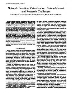


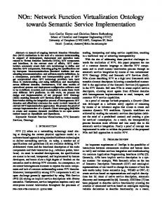
![[PDF] Download Network Functions Virtualization - Google Sites](https://m.moam.info/img/260x300/pdf-download-network-functions-virtualization-goog_6478ae1a097c474b228d7731.jpg)
![[PDF] Download Network Functions Virtualization - Google Sites](https://m.moam.info/img/260x300/pdf-download-network-functions-virtualization-goog_6478ae30097c474d228d6bfa.jpg)
![End to End Network Function Virtualization Architecture Instantiation [PDF]](https://m.moam.info/img/260x300/end-to-end-network-function-virtualization-archite_64a81cd6098a9e09738b4570.jpg)
![Network Function Virtualization Promises More Agility at ... - HPE.com [PDF]](https://m.moam.info/img/260x300/network-function-virtualization-promises-more-agil_64d01fdf098a9e383d8b45ad.jpg)


