able to learn color discrimination knowledge during training that accounts for hue ... proposed a skin color detection system with mean-based surface flattering.
Increased Performace of FPGA-Based Color Classification System Junguk Cho, Bridget Benson, Sunsern Cheamanukul, and Ryan Kastner Department of Computer Science and Engineering University of California, San Diego La Jolla, CA 92093, United States {jucho, b1benson, scheaman, kastner}@cs.ucsd.edu Abstract—This paper presents a hardware architecture for increased performance of color classification. In our architecture, color classification, based on an AdaBoost algorithm, identifies a pixel as having the color of interest or not. We designed the proposed architecture using Verilog HDL and implemented the design in a Xilinx Virtex-5 FPGA. The architecture for color classification can have 598 times performance improvement over an equivalent software solution and 1.9 times performance improvement over the leading hardware color classifier. Keywords-AdaBoost; architecture; FPGA; image processing; Verilog HDL
I.
color
classification;
INTRODUCTION
Color is an important feature in image processing as it allows for fast processing and robustness to geometric variations. Color classification is the act of identifying colors of interest in images. Color classification algorithms need a distinct set of color descriptors to allow for color discrimination of one object from another. Potential color classification applications include object detection, object tracking, human computer interaction, food classification, intelligent robots, and biomedical image analysis. A high frame processing rate and low latency are important for these applications that must provide quick decisions. Numerous approaches have been proposed for color classification. Askar et al. [1] present a robust method for skin color segmentation of moving hands for a real-time application. They proposed to adjust the thresholds for skin color segmentation automatically according to the specific participant and the illumination conditions. Somatilake and Chalmers [2] proposed a food classification system to grade six types of fresh produce using color images. Reyes et al. [3] presented an Adaboost learning based Fussy color contrast fusion color classification algorithm. Their system is able to learn color discrimination knowledge during training that accounts for hue and saturation drift of the target color. It is suitable for real-time color object recognition and contributes to accurate calculation of object position and orientation for the robot soccer game application. Lu and Zhang [4] presented an adaptive color classification algorithm and implemented the color classification algorithm in a RoboCup vision system. They used a Gaussian Mixture Model of two components to model the distribution of a color class in the YUV color space. Programmable hardware in the form of FPGA has been proposed as a conventional platform to exploit image processing in order to achieve high performance. Jin et al. [5]
proposed a skin color detection system with mean-based surface flattering. They implemented the design in an FPGA for real-time processing. Zhou et al. [6] presented a color image classification algorithm for mobile robot navigation. In order to calibrate the object color in different lighting conditions, a kind of statistic ellipsoidal model was constructed. They implemented this method on an FPGA for a mobile robot. Paschalakis and Bober [7] presented the issue of face detection and tracking in the context of mobile videoconferencing. Their proposed face detection and tracking method adopts the color-based face detection philosophy, due to its combined high performance and computational efficiency potential. They also examined an FPGA implementation of the proposed algorithmic frame work. This paper presents hardware architecture for increased performance of color classification. In our architecture, color classification is based on an AdaBoost algorithm [8] that identifies a pixel as having the color of interest or not. The main contribution of our work, described in this paper, is the design and implementation of a physically feasible hardware system to accelerate the processing speed of the operations required for real-time color classification. Therefore, this work has resulted in the development of a real-time color classification system employing an FPGA implemented system designed by Verilog HDL. Its performance has been measured and compared with the equivalent software and hardware implementations. The paper is organized as follows: In Section 2, we explain the color classification algorithm. In Section 3, we describe the hardware architecture, designed with Verilog HDL, of the color classification system. We also present the implementation of our real-time color classification system in an FPGA. In Section 4, we show the performance of the proposed system. We conclude in Section 5. II.
COLOR CLASSIFICATION ALGORITHM
For the color classifier, we identify pixels of a particular class. Each classifier is a binary classifier which can only tell that a pixel is from a class or non-class. It is possible to make a multi-classifier by combining the output of multiple binary classifiers. The training data are 320×240 RGB images from a color camera. We mark either a point or a rectangle as a positive or negative example of a class. The feature values of a pixel are HSV values (converted from RGB). For each pixel on an image, the hue, saturation and value of intensity are calculated and passed to trained binary classifiers. The classifier then outputs whether the pixel has the color of
interest. The binary classifier is trained using boosting on images obtained from the actual setup of the system. There are two reasons for doing this. First, we do not need to make any assumptions about the underlying distribution of the color space. Second, by using data from the actual setup, this automatically calibrates the system and no further calibration is needed. We generate the color classifier offline by feeding our training images and their positive and negative annotations to AdaBoost [8]. The training is performed using active training [9]. In the beginning, we start by marking color of interest and non-color of interest regions on each image. Then, a training set of color of interest and non-color of interest is sampled from all images. In each iteration of active training, the trained classifier is improved since hard examples and mistakes are introduced into the training set. Typically, our initial training set has about 15 images containing 20,000 samples of each type (color of interest and non-color of interest). When the training is done, boosting outputs a trained classifier which is represented as an alternating decision tree [10]. The alternating decision tree structure consists of two components: decision nodes and prediction nodes. Decision nodes specify a predicate condition. Prediction nodes specify a value to add to the score based on the result of the decision node. Each decision node can be seen as a conjunction between a precondition (the decision node was reached) and the condition specified in the decision node. The actual order that the alternating decision tree nodes are evaluated will likely be different than the order in which they were created, but all nodes in the higher branches of the tree must be evaluated before the nodes in the lower branches. In general, either breadth-first or depth-first evaluation will yield the correct interpretation. If a decision node is not reached then the node's predicate and subsequent prediction nodes will not be evaluated. The trained classifier describes if a particular pixel belongs to the color of interest or not. Our color classifier includes 99 binary classifiers to classify a pixel as having color of interest or not. It outputs a large value if the pixel belongs to the color of interest and a small value if the pixel does not. III.
HARDWARE ARCHITECTURE / IMPLEMENTATION
Figure 1 shows the overview of the proposed architecture for color classification. It consists of six modules: image interface, frame grabber, RGB to HSV converter, color classifier, display, and DVI interface. The image interface and DVI interface are implemented using ASIC custom chips with the FPGA board. The others are designed using Verilog HDL and implemented on an FPGA in order to perform color classification in real-time. The frame grabber controller generates the control signals for the image interface, and transfers images and sync signals from the image interface module to all of the modules of the color classification system. The RGB color space has a weakness in representing shading effects or rapid illumination changes [11]. To solve this problem, we consider converting from the RGB to HSV color space. The HSV model defines a color space in terms of three constituent components. Hue is the color type such as red,
Figure 1. Block diagram of proposed color detection system.
blue, or yellow that ranges from 0 to 360 degrees. Saturation is the vibrancy of color that ranges from 0 to 100%. The lower the saturation of a color, the more grayness is present and the more faded the color appears. Value of intensity is the brightness of the color that ranges from 0 to 100%. These ranges are not suitable for a hardware implementation, so they are normalized to 0 to 255 (8-bit) in the RGB to HSV converter. The HSV color image is obtained from the RGB color image using the converting equation [11]. The RGB to HSV converter module has a latency of 25 clock cycles and thus uses a pipeline structure to improve the processing speed of the RGB to HSV conversion. The RGB to HSV converter module also produces sync signals to synchronize all processes of the color classification in the HSV color space. The color classifier module performs the classification of color of interest. This module consists of classifiers, training data, comparators, accumulators, delayer, and comparator blocks to perform the color classification as shown in Fig. 2. The skin color classification is based on the AdaBoost algorithm [8] which identifies a pixel as having the color of interest or not. The color classifier includes k (100) binary classifiers to classify the color of interest in the images. The color classifier requires substantial computation because all pixels in the image should be classified with these classifiers sequentially. A general purpose computer of Von Neumann architecture has to process k×width×height (100×640×480= 30,720,000) classifications for each image when it processes an image with width×height (640×480) pixels. It may take a long latency delay every frame. In order to reduce processing time, we propose a specific architecture for the color classification. The architecture has a pipeline scheme which includes n (10) parallel classifiers blocks, n (10) corresponding to a constraint parameter given to AdaBoost algorithm. Each classifiers block has k (100) binary classifiers which are performed concurrently. A classifiers block evaluates k (100) binary classifiers by comparing the appropriate hue, saturation, or value of intensity value. The classifiers block then stores the result of the k-1 (99) binary classifiers (the result of the root node is always true) in the
...
...
result register and stores information about links between nodes in the link register. Figure 3 shows the block diagram of the classifiers blocks in the color classifier module. This block consists of binary classifiers, and result and link registers. If a binary classifier has true value, its bit of the result register has the value of 1. Otherwise, its bit of the result register has the value of 0. If the decision node of a binary classifier is reached, its bit of the link register has the value of 1. Otherwise, its bit of the link register has the value of 0. When a pixel passes each classifiers block, its result and link registers are updated concurrently. The value of the result register is calculated once in the first classifiers block (Classifiers 0) and then is just transferred to the result register of the adjacent classifiers block (Classifier n (n>1)) as shown in Fig 3. The link register, however, must be updated based on the previous link register in each classifiers block, to determine the list of decision nodes present in the solution for the current pixel. The values of the result and link register from the last (n-th) classifier block are used for an analyzer which makes an alternating decision tree of the current pixel. The training data for the color classification are stored as parameters in registers because they can be accessed quickly and simultaneously and modified easily. The accumulators perform the accumulation of the score of k (100) binary classifiers based on the alternating decision tree obtained from the analyzer. The comparator determines the classification of the color of interest. If the sore value obtained from the accumulators is larger than the threshold (1.0~2.0), the pixel belongs to the class of the color of interest. Otherwise, the pixel belongs to the class of the noncolor of interest. If the pixel is the color of interest, the comparator produces a detect signal and the position of the detected pixel. The delayer keeps the position of the processing pixels in the color classifier module and produces the position of the detected pixel. The color classifier module has a latency of 12 clock cycles where the n (10) parallel classifiers blocks require 10 clock cycles and the accumulators require 2 clock cycles to calculate the final score from k (100) binary classifiers. The display module stores the position of the pixels of the color of interest which is transferred from the color classifier module and makes a binary image of the color of interest of an image. The binary image is processed by the morphological operation of opening (erosion followed by dilation) to eliminate spot noises. The display module also displays the regions of the color of interest on the images by changing the pixel color to the green color. Therefore, the classified pixels of the color of interest show only green color while the pixels of the non-color of interest show their own color. The display module consist of analyzers, binary images, line buffers, window buffers, erosion, dilation, address generator, and print blocks as shown in Fig. 4. The analyzer receives the detect signal and the position of the detected pixel including the color of interest and makes a binary image of the color of interest from an input image in dual port BRAMs. The size of BRAMs for the binary image is the same as the resolution of the input images (640×480×1-bit). One port (port_a) is used to generate the binary image of the color of interest from an input image; the
Figure 2. Block diagram of the color classifier module.
Figure 3. Block diagram of the classifiers blocks.
Figure 4. Block diagram of the display module.
other port (port_b) is used to read the generated binary image for the morphological operation of opening to eliminate spot noises of the color classification. There are two operations; erosion followed by dilation. In order to perform these operations, we need a 3×3 window buffer which contains the necessary values of a binary image for each operation [12]. We designed the specific architecture that consists of the line buffers and window buffer to generate the 3×3 window in a single clock cycle for morphological operation. In this architecture, the line buffers store some parts of a binary image. The line buffers use dual port BRAMs where the number of BRAMs (2) is the same as the value of row-1 (3-1=2) in the window buffers. Each dual port BRAM can store one line of a binary image. Thus, the x-coordinates (0~width: 0~640) of the binary image can be used as the address for the dual port BRAM. Since each dual port BRAM stores one line of a binary image, it is possible to get a value from every line simultaneously. The result
value of erosion is transferred to the other line buffers and window buffers to generate the other 3×3 window buffers for dilation. The result value of dilation is transferred to the other analyzer to generate the other binary image. The printer reads the value of the other binary image according to the address generator to display the regions of the color of interest on the image by changing the pixel color to the green color (RGB: 0 255 0). The regions of the color of interest show only green color while the regions of the non-color of interest show their own color. In the display module, the Digital Visual Interface (DVI) specification is applied to display the processed image sequence to the LCD monitor through a DVI transmitter in the DVI interface module. IV.
EXPERIMENT / RESULTS
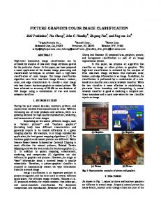
The proposed architecture for color classification has been designed using Verilog HDL, synthesized using XST, and implemented on a Virtex-5 FX70T FPGA using ISE design suite 10.1. Note that less than 15% of the device resources are allocated for color classification. We implemented two color classification examples; skin color of people and orange color of a buoy underwater. The color of the classified pixel which has the color of interest is changed to the green color. It means the color can be classified successfully. We measure the performance of the proposed architecture for the color classification system. The color classification system is capable of processing an image consisting of 640×480 at speeds of a maximum of 233.21 fps. The performance of the software program is determined by measuring the computation time required for performing color classification on the PC; in this case using an Intel Pentium D CPU (3.0 GHz), 4 GB DDR2 RAM (800 MHz), and Fedora 9.0 Operating System. All of the software programs are developed using Java (1.6.0). The algorithm and parameters used in software color classification are exactly the same as those of the hardware color classification. When the color classification, using the software program, is applied to the same conditions as the hardware color classification, it is capable of processing an image at speeds of an average of 0.39 fps with 640×480 images, and 0.69 fps with 320×240 images, respectively. The hardware color classification system has the performance improvement of 598 times over the software color classification system when applied to the 640×480 resolution images. In the hardware implementation by Jin et al. [5], the color classification system can process a 640×480 image up to 120 fps on a Virtex-4 LX200 FPGA. Our system has the performance improvement of 1.9 times over the Jin et al. implementation. The hardware implementation by Jin et al. [5] used 64583 (36%) Slice LUTs of Virtex-4 LX 200 FPGA (178176 available). Our system uses only 6207 (13%) Slice LUTs of Virtex-5 FX70T (44800 available). It saves 10 times the system resources of the Jin et al. implementation. Although, the hardware implementation by Paschalakis and Bober [7] can process a 176×144 image (25,344 pixels) up to 400 fps on EP20K1000EBC652 FPGA, the processed image is 12 times smaller than a 640×480 image (307,200 pixels). Therefore the performance of the Paschalakis and Bober [7]
implementation will decrease about 12 times (33 fps) when applied to a 640×480 image. In the hardware implementation by Zhou et al. [6], the classification costs 120ns. In order to compare the performance, the performance of our system can be calculated to the processing time of a pixel. In our system, the classification costs about 54ns. Therefore, our system has the performance improvement of 2.2 times over the Zhou et al. [6] implementation. V.
CONCLUSION
We present hardware architecture for increased performance of color classification. In our architecture, color classification is based on an AdaBoost algorithm that identifies a pixel as having the color of interest or not. We designed the proposed architecture using Verilog HDL and implemented the design in a Xilinx Virtex-5 FPGA. The architecture for color classification can have 598 times performance improvement over an equivalent software solution. The proposed color classification system has the performance improvement of 1.9 times over the Jin et al. implementation, 7.0 times over the Paschalakis and Bober implementation, and 2.3 times over the Zhou et al. implementation. REFERENCES [1]
S. Askar, Y. Kondratyuk, K. Elazouzi, P. Kauff, and O. Schreer, "VisionBased Skin-Colour Segmentation of Moving Hands for Real-Time Applications," European Conference on Visual Media Production, pp. 7985, 2004.
[2]
S. Somatilake and A. N. Chalmers, "An Image-Based Food Classification System," Image and Vision Computing New Zealand, pp. 260-265, 2007.
[3]
N. H. Reyes, A. L. Barczak, and C. H. Messom, "Fast Colour Classification for Real-time Colour Object Identification: Adaboost training of Classifiers," Conference on Autonomous Robots and Agents, 2006.
[4]
X. Lu and H. Zhang, "Color Classification Using Adaptive Dichromatic Model," IEEE Conference on Robotics and Automation, pp. 3411-3416, 2006.
[5]
S. Jin, D. Kim, T. C. Pham, and J. W. Jeon, "FPGA Implementation of Real-time Skin Color Detection with Mean-based Surface Flattening," ACM/SIGDA Symposium on Field Programmable Gate Arrays, pp. 283287, 2009.
[6]
Q. Zhou, K. Yuan, Hui Wang, and H. Hu, "FPGA-Based Colour Image Classification for Mobile Robot Navigation," IEEE Conference on Industrial Technology, pp. 921- 925, 2005.
[7]
S. Paschalakis and M. Bober, "Real-Time Face Detection and Tracking for Mobile Videoconferencing," Real-Time Imaging, Vol. 10, No. 2, pp. 8194, 2004.
[8]
Y. Freund and R. E. Schapire, "A Decision-Theoretic Generaliztion of OnLine Learning and an Application to Boosting," Journal of Computer and System Sciences, no. 55, pp. 119-139, 1997.
[9]
S. Cheamanunkul, E. Ettinger, M. Jacobsen, P. Lai, and Y. Freund, "Detecting, Tracking and Interacting with People in a Public Space," Conference on Multimodal Interfaces, pp. 79-86, 2009.
[10] Y. Freund and L. Mason, "The Alternating Decision Tree Learning Algorithm," Conference on Machine Learning, pp. 124-133, 1999.
[11] J. U. Cho, S. H. Jin, X. D. Pham, D. Kim, and J. W. Jeon, "FPGA-Based Real-Time Visual Tracking System Using Adaptive Color Histograms," IEEE Conference on Robotics and Biomimetics, pp. 172-177, 2007.
[12] J. Cho, S. Mirzaei, J. Oberg, and R. Kastner, "FPGA-Based Face Detection System Using Haar Classifiers," ACM/SIGDA Symposium on Field-Programmable Gate Arrays, pp. 103-112, 2009.