Increasing the Reliability of Wireless Sensor Networks with a Unit Testing Framework Jan Beutel, Christian Plessl, Matthias Woehrle TIK Report No. 272 Computer Engineering and Networks Lab, ETH Zurich 8092 Zurich, Switzerland
real-world operation
application goal
?
testbed
milestone
abstract
Abstract— Designing Wireless Sensor Networks (WSNs) has proven to be a slow, tedious and error-prone process due to the inherent intricacies of designing a distributed, wireless, and embedded system. Previous projects have shown that it is vital to follow a systematic design approach accompanied by an end-toend test methodology to satisfy all design requirements including robustness and reliability in a newly developed application. In this paper, we propose the fundamentals of such a test methodology. We present essential features of a framework suitable for testing a broad range of WSN applications. We demonstrate with a case study that our test methodology is a feasible approach by integrating a number of available design-tools for the TinyOS operating system. While we target TinyOS in the case study due to its widespread use in WSN applications, the proposed test methodology is general and not tailored to a single WSN platform or operating system.
real
beutel|plessl|
[email protected]
boundary of sim ulation
simulation 1
5
10
100
1000
# nodes
I. I NTRODUCTION
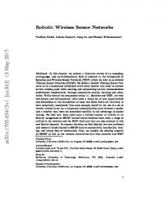
Fig. 1. WSN development process: moving from abstract simulation of few nodes to real-world operation of many nodes
The characteristics of Wireless Sensor Networks renders the design of applications inherently challenging. A WSN is a distributed system that shows a large degree of parallelism. Each WSN is essentially an autonomous embedded system with stringent constraints on energy, storage and memory resources. Its wireless nature introduces an unreliable communication channel requiring robust and resilient communication protocol design. When deployed in an unprotected environment, external influences such as noisy radio channels or wide temperature variations can considerably influence the application and require adequate countermeasures to be taken at design time. Since many WSNs aim at continuous and autonomous operation for up to multiple years with only limited or no access and supervision, deploying a correct WSN application is of utmost importance. Motivated by our own experiences and discussions with industrial partners, we argue that a systematic design approach accompanied by an end-to-end test methodology is key to overcome these intricacies and to build sustainable WSN systems. A test methodology shall enable a design team to continuously monitor the correctness of an implementation. In this work we consider only test cases, that have a binary result: pass or fail. This concept is sufficiently flexible for many scenarios. A test case can verify a single property of the implementation (e. g., whether two WSN nodes can communicate), but also complex behavior as long as the result of the test is binary (e. g., transmit large amounts of
data and check whether the packet loss rate is below an acceptable threshold). Test cases can also check for nonfunctional properties, such as time and energy used, if these properties are accessible. Figure 1 illustrates possible paths in the process of developing a typical, large scale WSN application. The topright corner represents the goal of the development process, an application running in real-world on 1000 WSN nodes. Typically, such a large scale application is developed by simulating a small number of nodes first. After the simulation passes a formal or informal test procedure, the developer faces two choices: either the application is refined and implemented on a testbed, or the simulation is extended to include more WSN nodes. Detailed simulation of large WSNs requires significant computing resources. Hence, large scale WSNs can be simulated only with a reduced accuracy and fidelity of the simulation results. In general, porting an application that has been validated in simulation to the testbed is not trivial, due to incorrect simulation assumptions, limited debugging capabilities in the testbed, and possibly stricter resource constraints on the WSN target nodes. There exist a number of widely used tools that can serve as building blocks for a test framework, e. g., WSN simulators (TOSSIM [1]), microcontroller instruction set simulators (AVRORA [2]) and testbeds (MoteLab [3], EmStar [4],
DSN [5]). In pursuit of the design goal to achieve robust and efficient WSN implementations a number of techniques focussing on in-networking debugging (Marionette [6], packet sniffing [7], Sympathy [8], VigilNet [9]), languages (Attributed State Machines [10], TinyOS [11]), design and architectural principles (MNet [12]) have been proposed. While each of these tools addresses a highly specific part of the WSN development tool-flow, there exists no established test framework for WSNs. We propose to leverage the functionality of existing tools and to integrate them into a comprehensive test framework. We aim at a test approach that allows us to use the same test cases for testing in simulation, on the testbed and in real-world. The seamless transferability of test cases between the different abstraction levels allows for guiding the development process from specification to implementation while continuously ensuring the correctness of the implementation. The concepts and methodology proposed in this paper augment today’s best practices in WSN testing. Our test framework may be combined with other design methodologies to improve reliability, like tools to support a correct-by-construction design process. While in-network debugging techniques detect failures based on passive monitoring of the system’s behavior, we suggest to actively stimulate the system to verify the application’s correctness by selecting a representative sample of scenarios. This paper is organized as follows: Section II introduces our test methodology and defines the components of the test framework. Section III presents an implementation of our test methodology targeting TinyOS 2 applications. In a case study, we present results from applying the methodology to a typical WSN application. Finally, we summarize our work, draw conclusions and outline future work. II. A WSN TEST METHODOLOGY AND FRAMEWORK In this section, we propose a design flow for WSN testing and introduce the necessary terminology. A. Testing Framework Architecture We propose a test methodology that is strongly inspired by unit testing, which is a widely used technique for general software testing. The key idea of unit testing is to integrate self-testing capabilities into the tests by formally specifying the inputs to the software under test as well as specifying the expected results of the test in an executable format. This allows for full automation of the test procedure. Automated testing promotes frequent execution of the tests and enables the designer to continuously compare the implementation’s behavior with the specification. The key property of our proposed methodology is that it allows the designer to provide a unified specification of a test case. The same test case can be executed on different test platforms: real hardware (e. g., using a testbed) or a simulator. The simulation can target different levels of abstraction, e. g., pure functional simulation, functional simulation with a refined radio channel model, cycle-accurate execution on
test case test driver enviroment
SUT
stimuli
logged events
testMonitor monitor checker
verification
specification requirements
Fig. 2.
Exemplary test case architecture
an instruction set simulator, etc. The framework does neither implement nor imply the capability to automatically translate a design across abstraction levels. Instead, the framework allows for defining test cases that are valid and executable on all abstraction levels. The framework provides the generation of test components tailored to a specific test platform relying on a unified specification. Hence, the resulting reusability of the applicationspecific test specification promotes multi-platform testing. This increases the ease of use of the framework, allows for automatic verification of the software under test, and thus helps to detect possible regression bugs. B. Test Specification By testing a WSN we understand the execution of a test suite that is a collection of test cases. The architecture of a test case is illustrated in Fig. 2 and is discussed in the following. 1) software under test: We denote the application software that is subject to the test procedure as software under test (SUT). The level of abstraction of the SUT typically declines over the course of the project. Initially a high-level software model for simulation of multiple nodes may be preferred or a detailed node model focussing on the network layer neglecting other implementation details. The ultimate target for the SUT is the software to be run on the real hardware mote including any detail necessary to run the considered application sustainably in the targeted environment. 2) test drivers: A test driver implements the inputs, so called stimuli, that are applied to the SUT during the execution of the test. Each stimulus is characterized by its value (or type) and the time when it is applied to the SUT. The sequence of stimuli generated by the test driver can be arbitrarily complex. Static drivers apply a single event to the SUT (e. g., a start signal) or stimulate the application with a predefined sequence of events. More general dynamic drivers can also include feedback. Dynamic drivers read the SUT’s state or outputs and react to the dynamic response of the system.
3) test monitors: Test monitors observe functional and nonfunctional properties. These test results are provided to the test checkers after the test’s execution. The monitors can observe or compute properties and results at runtime. Some properties may only be determined after the test has been executed, e. g., the total packet loss rate. For these test cases the monitors store the intermediate data during the test and convert the data to the suitable representation for the checkers after the execution of the test. A test monitor can also be implemented as a part of the application running on the WSN node to allow for fine grained observations on real system implementations. These monitors are denoted as target monitors. Using such “insitu” monitoring however requires meticulous care in the implementation and retrieval of the logs generated as every cycle executed and every byte transfered on a WSN node ultimately alters the application behavior. Readily available monitor primitives provided by the test framework may be used for timing uncritical code sections. 4) test environment: The test environment is a collection of functions, that incorporate and model all parameters of the environment that are relevant for the tests. The relevant parameters for a specific test are determined by the scenario defined in the test case. The test case defines the position and mobility of nodes and hence the network topology. Depending on the abstraction level certain aspects of the environment can be included, simplified or excluded. For example, in our case study presented in Section III, we are testing an application that collects and aggregates sensor readings from a number of WSN nodes. For verifying the communication protocols we can disregard the modelling of actual sensor values. 5) test checkers: Test checkers are binary decision functions for validating the system’s execution according to the functional and non-functional requirements of the specification. The inputs to the checkers are provided by the test monitors. The output of a checker is either “test passed” or “test failed”. The restriction to a binary decision does not limit the applicability of checkers to the verification of simple properties, e. g., checking whether a node reaches a certain end state. The checkers can aggregate data from the monitors and, for example, check whether the packet loss rate does not exceed a specified threshold. When implementing a test case, the designer must be aware that the checker is applied to different abstraction levels, e. g., to the simulation and to the testbed execution. It is important, that the checker is valid on all desired abstraction levels. Generally, the definition of a checker for an application is independent of the test platform. For example, to deal with a potential mismatch of timing information in simulation, it is not advisable to rely on absolute timing for a sequence of events, but to check only for the order of the events. However, platform-specific checks or even tests for particular properties may be added with a platform identifier. This allows the test framework to selectively check for properties
config prog init start
[
preparation
][
monitor
data collection stop
stimuli
execution logging
]
control
driver
... wait ...
[
post-processing checker
]
pass/fail
test duration
Fig. 3. Timeline of the test procedure of an exemplary test case including interactions with the test framework components.
depending on the abstraction level and to support application requirements that cannot be formulated independently of the platform. C. Test Procedure The test procedure is divided in three phases: test preparation, test execution, and result verification. Figure 3 visualizes the distinct phases of the test execution. 1) test preparation: In the test preparation phase, the application code is compiled for the execution plattform. Depending on the test case, the appropriate test drivers and test monitors are loaded. On a simulation platform, the SUT program is loaded into the simulator and the environment is configured according to the specification in the test case. For executing the test on a testbed, the application code is distributed and programmed to all WSN nodes. Communication channels between the test framework host computer and the WSN nodes must be established for the drivers and monitors. The WSN nodes are initialized to a predefined state. A test may define an initial state corresponding to power-on right after deployment or load a checkpoint representing the SUT at a particular point in its operation lifetime by setting buffers or queues to specific values derived by analysis or simulations. 2) test execution: In the execution stage the SUT is executed reacting to the test driver’s stimuli and subsequent internal events in the selected environment. The test monitors observe and log all functional and non-functional data as defined. The test runs until a predefined result or system state is detected or for a given number of cycles or events. Break points may be added for easier debugging, e. g., to analyze race conditions in connection to an event. Test primitives may stop or pause the test on defined assertions. Simulations may be either event-driven for faster execution time or cyclebased, e. g., to run on an instruction-level simulator for the microcontroller. 3) result verification: In the result verification phase, the data collected by the monitors is retrieved and compared to the expected results defined in the checker. On a simulation platform the data is typically available in logfiles that have been written during the test execution. On a testbed platform, it may be required to request and retrieve the data from a distributed logging facility. In some cases it may be required to post-process the data collected, before the test results can be determined by the checkers.
TOSSIM
pass/ fail
DSN testbed
pass/ fail
Test Case Driver Enviroment
MultihopOscilloscope application
WSN
Stimuli
TOSSIM
simulation platform
(executable)
pass/fail Log Events
Monitor Monitor Monitor Checker
Verification
Specification requirements
TinyOS 2 app
test driver
(C/NesC)
(Python)
Fig. 4. Case study architecture with test execution on two abstraction levels
test monitor
(Python/C/NesC)
test checker (Python)
DSN node UAR T
DSN database
unified testcase testbed platform
Tmote app.
(code image)
III. T ESTING F RAMEWORK : A C ASE S TUDY In this section we present a case study based on an exemplary application, tested on two selected test platforms, see Fig. 4. The case study validates the feasibility of our approach. It demonstrates an example implementation of the methodology for the TinyOS 2 operating system and Tmote WSN nodes and integrates existing tools into an automated test framework. A. Software under test The SUT is a sensor data collection application based on the well-known MultihopOscilloscope application, which is part of the TinyOS 2.0 distribution. The application is a typical WSN application that sends locally collected sensor data to sink nodes. The data is routed over a multihop collection tree. We have extended the application such that oscilloscope packets are sent and forwarded by the nodes only when an enable flag is set. The TinyOS dissemination protocol is used to distributes changes to this enable flag at runtime to all nodes. Our target is to design a reliable data collection application running on Moteiv Tmote Sky nodes that satisfies the requirements as specified in our test case, see Sec. III-C. B. Test platforms We selected two commonly used platforms for WSN testing, a standard WSN simulator and a testbed. For the simulation of our TinyOS application we selected the TOSSIM simulator [1] integrated into the TinyOS distribution. TOSSIM is a prominent example of an eventdriven simulator allowing to use the actual TinyOS application code. It can simulate multiple nodes and features simulation primitives for modelling the communication channels of the nodes. For the testbed platform, we have selected the Deployment Support Network (DSN)[5] installation available at ETH. The DSN is a wireless testbed infrastructure, that allows for testing different types of WSN nodes. Each target node is attached to a DSN node providing access channels between the targets and the test host. We use the existing interface to connect to our Tmote Sky targets.
Fig. 5.
Case study test flow for both platforms
At the beginning of the test the driver powers on all target nodes. Initially, the flag that controls the data collection is disabled. After a defined idle interval, allowing the nodes to setup the routing tree, the driver sets the enable flag on the sink node. Sensor data is collected for a predefined duration. Subsequently, the enable flag is reset and the test case ends after a phase-out interval. A TinyOS-based target monitor was developed that can be attached to different watchpoints inside an application. In our SUT we attach the target monitor to the following functions: 1) sending local sensor data packets, 2) packet forwarding to host on sink node, 3) boot sequence including code version and node id, and 4) enable flag changes. The checker uses the monitor information from 1) and 2) to derive the average packet yield, which is defined as the ratio of the number of packets the sink node forwards to the host and the sum of local sensor data packets sent by all nodes. The pass or fail condition defined in this test case is an average packet yield of 90%. D. Test flow Figure 5 depicts the test flow for the example application with a unified test case, and the according toolchain for the two test platforms. The starting point of the test flow is an instrumented TinyOS 2 application. In a (so far manual) preprocessing step, the generic test primitives are replaced by platform-specific test framework interfaces. The driver for the simulation communicates with TOSSIM via the built-in python interface. A TOSSIM-based debug function directly generates monitor output in a common monitor output format. For the testbed, an according python script executes commands via an XML-RPC interface to the DSN nodes. Monitor data is retrieved from a database and subsequently formatted. The common monitor output format allows for using the same checker for both test platforms. The checker outputs a pass or fail notification based on the previously specified requirement.
C. Test case The test case defines 10 nodes set up in a typical office environment. We fit the TOSSIM radio model parameters to reflect the topology and communication characteristics of this environment. The parameter fitting is based on data from previous link quality measurements for the Tmote targets.
E. Test results We ran each test case 40 times on each test platform. Running a test case on the simulation platform takes about 0.5 min whereas a run on the testbed takes approximately 11 min. The test time differences are due to differences in
packet yield [%]
100
pass 90
fail TOSSIM Simulation
80 70
DSN testbed 60 50 40
0
5
10
15
20
25
30
35
40
45
# test runs
Fig. 6. 40 independent test runs ordered according to the resulting packet yield. 32 out of 40 simulation results passed the test criteria of an average packet yield ≥ 90%.
the execution time on the platform and significant overheads in pre- and post-processing steps. These overheads motivate the aggregation of test cases to test suites to avoid extensive use of expensive operations like code distribution and target programming for the testbed platform. Figure 6 presents the average packet yield the checker derived for each test case. The data in the graph is sorted with respect to the packet yield to point out its distribution. Deficiencies of the testbed currently not accustomed for in the test framework inferred test artifacts that have been pruned from the result set. While 20% of the TOSSIM test cases failed, no test result on the testbed platform passed the defined criteria. The distribution of packet yields for both platforms follow a similar trend. The results show, that the simulation assesses the packet yield overly optimistic. Future work needs to determine the cause for this considerable mismatch. However, the lower than expected packet yield is in line with observations from other researchers reported in literature (GDI yield of 58%, California redwoods yield 40%, Ecuador volcano yield 68% [12]). IV. C ONCLUSIONS AND F UTURE W ORK The main contribution of this paper is the proposal of a test methodology and framework for WSNs. The methodology is based on ideas from general software unit testing and allows for executing the same test cases on different test plaforms (e. g., simulation or testbed). The test framework allows for automatically verifying the correctness of the application during the design process. We have shown that an implementation of the test methodology is feasible by integrating available tools into a test framework for TinyOS applications. We have successfully applied the test framework for verifying an example application on two abstraction levels: in simulation and running on a testbed. We argue that the proposed design methodology leads to an improved WSN design flow and are confident that it allows for building more robust WSN applications. A thorough analysis based on applying our framework to different realworld applications will reveal if the pay-off in terms of application reliability justifies the additional effort of the
proposed methodology. Thus, we are planning to integrate additional platforms and to make the framework available to other researchers. For our case study, we have calibrated the radio channel model with radio channel measurements from the testbed. Nevertheless, we have noticed a considerable mismatch of the simulation and testbed test results. A promising extension of the automated test and logging capabilities provided by our framework is to work on automated back-annotation from testbed and deployment measurements to fit the environment model for the simulation. The fidelity of the simulation models may be further enhanced using in-network monitoring and packet sniffing techniques [7]. R EFERENCES [1] P. Levis, N. Lee, M. Welsh, and D. Culler, “TOSSIM: Accurate and scalable simulation of entire TinyOS applications,” in Proc. 1st ACM Conf. Embedded Networked Sensor Systems (SenSys 2003). ACM Press, New York, Nov. 2003, pp. 126–137. [2] B. Titzer, D. Lee, and J. Palsberg, “Avrora: Scalable sensor network simulation with precise timing,” in Proc. 4th Int’l Conf. Information Processing Sensor Networks (IPSN ’05). IEEE, Piscataway, NJ, Apr. 2005, pp. 477–482. [3] G. Werner-Allen, P. Swieskowski, and M. Welsh, “MoteLab: A wireless sensor network testbed,” in Proc. 4th Int’l Conf. Information Processing Sensor Networks (IPSN ’05). IEEE, Piscataway, NJ, Apr. 2005, pp. 483–488. [4] L. Girod, J. Elson, A. Cerpa, T. Stathapopoulos, N. Ramananthan, and D. Estrin, “EmStar: A software environment for developing and deploying wireless sensor networks,” in Proc. USENIX 2004 Annual Tech. Conf., June 2004, pp. 283–296. [5] M. Dyer, J. Beutel, L. Thiele, T. Kalt, P. Oehen, K. Martin, and P. Blum, “Deployment support network - a toolkit for the development of WSNs,” in Proc. 4th European Workshop on Sensor Networks (EWSN 2007), ser. Lecture Notes in Computer Science, vol. 4373. Springer, Berlin, Jan. 2007, pp. 195–211. [6] K. Whitehouse, G. Tolle, J. Taneja, C. Sharp, S. Kim, J. Jeong, J. Hui, P. Dutta, and D. Culler, “Marionette: using RPC for interactive development and debugging of wireless embedded networks,” in Proc. 5th Int’l Conf. Information Processing Sensor Networks (IPSN ’06). ACM Press, New York, 2006, pp. 416–423. [7] M. Ringwald, M. Cortesi, K. Römer, and A. Vialetti, “Demo abstract: Passive inspection of deployed sensor networks with SNIF,” in Adjunct Proc. 4th European Conf. Wireless Sensor Networks (EWSN 2007), K. Langendoen and T. Voigt, Eds., Delft, The Netherlands, Jan. 2007, pp. 45–46. [8] N. Ramanathan, K. Chang, R. Kapur, L. Girod, E. Kohler, and D. Estrin, “Sympathy for the sensor network debugger,” in Proc. 3rd ACM Conf. Embedded Networked Sensor Systems (SenSys 2005). ACM Press, New York, 2005, pp. 255–267. [9] T. He, S. Krishnamurthy, L. Luo, T. Yan, L. Gu, R. Stoleru, G. Zhou, Q. Cao, P. Vicaire, J. Stankovic, T. Abdelzaher, J. Hui, and B. Krogh, “VigilNet: An integrated sensor network system for energy-efficient surveillance,” ACM Transactions on Sensor Networks, vol. 2, no. 1, pp. 1–38, 2006. [10] O. Kasten and K. Römer, “Beyond event handlers: Programming wireless sensors with attributed state machines,” in Proc. 4th Int’l Conf. Information Processing Sensor Networks (IPSN ’05). IEEE, Piscataway, NJ, Apr. 2005, pp. 45–52. [11] P. Levis, S. Madden, D. Gay, J. Polastre, R. Szewczyk, A. Woo, B. E., and D. Culler, “The emergence of networking abstractions and techniques in TinyOS,” in Proc. First Symp. Networked Systems Design and Implementation (NSDI ’04). ACM Press, New York, Mar. 2004, pp. 1–14. [12] J. Choi, J. Lee, M. Wachs, and P. Levis, “Opening the sensornet black box,” Stanford Information Networks Group, Stanford University, CA, Tech. Rep. SING-06-03, 2006.