Indoor Localization: Automatically Constructing Today’s Radio Map by iRobot and RFIDs Lun-Wu Yeh1 , Ming-Shiou Hsu1 , Yueh-Feng Lee2 , and Yu-Chee Tseng1,3 1 Department of Computer Science National Chiao-Tung University, Hsin-Chu, 300, Taiwan 2 Industrial Technology Research Institute, Hsin-Chu, 310 Taiwan 3 Department of Information and Computer Engineering Chung-Yuan Christian University, Chung-Li, 320, Taiwan Email:
[email protected];
[email protected]; yuehfeng
[email protected];
[email protected]
0.25
10:00 14:00 16:00
0.2
Probability
Abstract—For outdoor localization, GPS already provides a satisfactory solution. For indoor localization, however, a globally usable solution is still missing. One promising direction that is proposed recently is the fingerprinting-based solution. It involves a training phase to collect the radio signal strength (RSS) patterns in fields where localization is needed into a database (called radio map). The radio signal could be from WiFi access points, GSM base stations, or other RF-based networks. Then, during the positioning phase, an object which is interested in its own location can collect its current RSS pattern and compare it against the radio map established in the training phase to identify its possible location. We present an interesting system based a robot and numerous cheap RFID tags deployed on the ground to automate the training process and, more importantly, to frequently update radio maps to reflect the current RSS patterns. This not only significantly reduces human labors but also improves positioning accuracy. Index Terms—indoor positioning, localization, pervasive computing, RFID, robot
0.15
0.1
0.05
0 -80
Fig. 1.
-75
-70 -65 -60 Signal Strength (dBm)
-55
-50
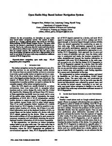
RSS patterns of an AP measured at different times.
I. I NTRODUCTION Recently, location-based services are regarded as one of the killer applications in mobile networks. A key factor in location-based services is the location estimation accuracy. For outdoor localization, GPS already provides a satisfactory solution. For indoor localization, however, a globally usable solution is still missing. Many indoor localization technologies have been proposed, such as infrared-based [1], ultrasonicbased [2], and RF-based [3] systems. Generally, localization models can be classified as AoA-based [4], ToA-based [5], TDoA-based [6], and fingerprint-based [3][7][8]. In this work, we are interested in fingerprint-based localization systems, such as RADAR [3]. This method does not rely on calculating signal fading in an environment. Instead, it relies on a training phase to collect the radio signal strength (RSS) patterns at a set of training locations from pre-deployed beacons in a sensing field into a database (called radio map). These beacons can be existing infrastructures, such as IEEE 802.11 access points, GSM base stations, or other RF-based networks. Then, during the positioning phase, an object to be localized can collect its current RSS pattern and compare it against the radio map established in the training phase to identify its possible location.
The major drawback of the fingerprinting approach is its labor-intensive training process, especially in a large-scale field. Further, since the RF signal is inherently unstable, the radio map collected earlier may deviate significantly from the current one. Manually calibrating radio maps is error-prone. Besides, environment may change, furniture may be moved, and beacons may be reconfigured or upgraded anytime [9]. Fig. 1 shows the RSS distribution of an AP collected at different times in one day, which shows significant variation. This may result in non-negligible errors when positioning objects. The above observation motivates us to design a self-guided robot to collect RSS patterns automatically. Our system contains some WLAN APs and a large number of RFID tags placed on the ground. The self-guided robot does a two-level positioning to identify its location. In the first level, a location server based on WiFi fingerprinting helps position it at meterlevel precision. The WiFi network can also provide the robot a local map containing the deployment of RFID tags in the field. In the second level, the robot searches the field and, if any RFID is scanned, its location is at the centimeter-level . With its accurate position, the robot can move around to automate
•
RFID tags
•
•
AP Location server
Self-guided robot
Fig. 2.
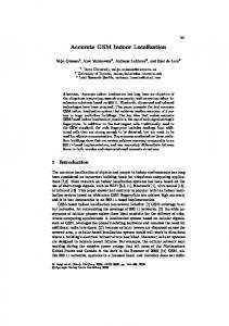
System architecture of our work.
the training process and, more importantly, to frequently update radio maps to reflect the current RSS patterns. This not only significantly reduces human labors but also improves positioning accuracy. We implement our system on iRobot Create [10], on which a WiFi interface and a RFID reader are attached. The rest of this paper is organized as follows. Section II describes some related works. Section III presents our design methodology. Section IV demonstrates our prototype. Section V concludes this work. II. R ELATED W ORKS Our goal is to automate the training phase via robots. To do so, a critical thing is to precisely navigate robots to visit each training point. In the past, indoor robot navigation systems can be divided into three categories: (1) laser guiding system [11], (2) magnetic tape guiding system [12], and (3) visionbased system [13]. Laser and magnetic tape guiding systems are more accurate but allow only limited routes. Vision-based systems are more flexible, but they require high computing cost and expensive equipments. Recently, RFID techniques have also been applied to robot navigation [14][15][16]. In [14][16], an array of short range passive RFID tags are deployed on the entire field. Each tag represents a unique location. On scanning these tags, the robot can calculate its location. Grid deployment is discussed in [14], while triangular deployment is discussed in [16]. As can be seen, both [14] and [16] will need a large number of RFID tags. The work [15] uses a rotatable RFID reader to guide a robot to a stationary target, which has an active tag as a location transponder. An AoA-like model is adopted to guide the robot. This solution is more costly and it is mainly for one single target. Our work uses passive tags and it takes advantage of existing WiFi networks for meter-level positioning. III. M ETHODOLOGY Fig. 2 shows our system architecture, which contains four components.
•
WiFi network: The network contains a number of APs, which periodically transmit beacons. By collecting signal strengths of these beacons, a device can estimate its current location. Location server: The location server runs a fingerprinting algorithm for positioning purpose. It also keeps some maps and those locations on the maps where RFID tags are deployed. The fingerprinting algorithm provides meter-level localization. RFID tags: RFID tags serve as landmarks, each identifying a unique location for centimeter-level localization. These tags are divided into groups, and each group is deployed in a cross shape as shown in Fig. 2. On scanning a tag, the robot can query the location server to get a local map as well as its location in the map. Self-guided robot: The self-guided robot has a WiFi interface and a RFID reader. It decides its location in two phases. Through collected RSS patterns, it can determine its rough location on a map. According to the map, it can further search for RFID tags. Once a tag is found, it knows its precise location.
Fig. 3 shows the working flow of the self-guided robot. At first, the robot gets a tour, which contains a sequence of entries, from the location server. These entries can be divided into two types: training point and RFID target. If the next entry is a training point, the robot moves toward it, collects the RSS patterns at that point, and reports to the location server for constructing the current radio map. Otherwise, the robot moves to the predicted location of the next RFID target. If no RFID tag is scanned (due to error), it searches in a spiral manner. IV. P ROTOTYPE Fig. 4 shows the hardware components of the self-guided robot. We adopt iRobot Create [10] as the mobile platform and attach to it a RFID reader, an electronic compass, and a notebook with a WiFi interface. Fig. 5 shows some searching scenarios of the robot. Fig. 6 shows our testing environment, which contains eight WiFi APs and six RFID tag groups. Our experiments show that 5 to 10 seconds are needed for the robot to visit each tag group and totally 3 to 5 minutes to construct a new radio map in this environment. V. C ONCLUSIONS Major drawbacks of the fingerprint-based position approach are its training cost and the signal deviation problem between the training phase and the positioning phase. We have developed a self-guided robot to conquer these problems. The twophase position algorithm helps the self-guided robot to position itself. In particular, RFID tags serve as landmarks to accurately position the robot at centimeter-level precision. With accurate locations, the robot can automate the training phase and, more importantly, frequently reconstruct the current radio map to improve the precision of the fingerprinting algorithm.
(1) Collect the RSS patterns. (2) Report to The Location server to construct today's radio map.
Move to the training point Training point Get a Tour from the location server
Get an entry from the tour
Type of the entry?
RFID
(1) Move to the predicted location of the target. (2) If no RFID tag is scanned, search in a spiral manner.
Next entry Next tour Fig. 3.
iRobot Create
Working flow of the self-guided robot.
Notebook (with WiFi interface)
RS232 muti-port controller
RFID reader
RFID Tag
Electronic compass
RFID tags
Fig. 4.
Hardware components of the self-guided robot.
ACKNOWLEDGES Y.-C. Tseng’s research is co-sponsored by MoE ATU Plan, by NSC grants 96-2218-E-009-004, 97-3114-E-009-001, 972221-E-009-142-MY3, and 98-2219-E-009-005, and by ITRI, Taiwan. R EFERENCES [1] E. Brassart, C. Pegard, and M. Mouaddib, “Localization using infrared beacons,” Robotica, vol. 18, no. 2, pp. 153–161, 2000. [2] N. B, Priyantha, A. Chakraborty, and H. Balakrishnan, “The cricket location-support system,” in Proc. of ACM Int’l Conference on Mobile Computing and Networking (MobiCom), 2000. [3] P. Bahl and V. N. Padmanabhan, “Radar: An in-building rf-based user location and tracking system,” in Proc. of IEEE INFOCOM, 2000. [4] D. Niculescu and B. Nath, “Ad hoc positioning system (aps) using aoa,” in Proc. of IEEE INFOCOM, 2003.
Fig. 5.
Some searching scenarios.
[5] M. Addlesee, R. Curwen, S. Hodges, J. Newman, P. Steggles, A. Ward, and A. Hopper, “Implementing a sentient computing system,” IEEE Computer, vol. 34, no. 8, pp. 50–56, 2001. [6] A. Savvides, C.-C. Han, and M. B. Strivastava, “Dynamic fine grained localization in ad-hoc networks of sensors,” in Proc. of ACM Int’l Conference on Mobile Computing and Networking (MobiCom), 2001. [7] S.-P. Kuo and Y.-C. Tseng, “A scrambling method for fingerprint positioning based on temporal diversity and spatial dependency,” IEEE Trans. on Knowledge and Data Engineering, vol. 20, no. 5, pp. 678–684, 2008. [8] J. J. Pan, J. T. Kwok, Q. Yang, and Y. Chen, “Multidimensional vector regression for accurate and low-cost location estimation in pervasive computing,” IEEE Trans. on Knowledge and Data Engineering, vol. 18,
27 m
13 m
Self-guided robot
Fig. 6.
RFID tag
Access point
Location server
Our experimental environment.
no. 9, pp. 1181–1193, 2006. [9] S.-P. Kuo, H.-J. Kuo, and Y.-C. Tseng, “The beacon movement detection problem in wireless sensor networks for localization applications,” IEEE Trans. on Mobile Computing, to appear. [10] iRobot. [Online]. Available: http://store.irobot.com/corp/index.jsp [11] K. Lingemanna, A. Nuchtera, J. Hertzberga, and H. Surmannb, “Highspeed laser localization for mobile robots,” Robotics and Autonomous Systems, vol. 51, no. 4, pp. 275–296, 2005. [12] Automated guided vehicle. [Online]. Available: http://en.wikipedia.org/ wiki/Automated Guided Vehicle [13] E. M. Lowa, I. R. Manchesterb, and A. V. Savkina, “A biologically inspired method for vision-based docking of wheeled mobile robots,” Robotics and Autonomous Systems, vol. 55, no. 10, pp. 769–784, 2007. [14] B.-S. Choi, J.-W. Lee, and J.-J. Lee, “An improved localization system with rfid technology for a mobile robot,” in Proc. of conference of IEEE Industrial Electronics (IECON), 2008. [15] M. Kim and N. Y. Chong, “Rfid-based mobile robot guidance to a stationary target,” in Mechatronics, 2007. [16] H. Lim, B. Choi, and J. Lee, “An efficient localization algorithm for mobile robots based on rfid system,” in Proc. of Int’l Joint Conference on SICE-ICASE, 2006.