Samir Moulahoum* Omar Touhami* * Rachid Ibtiouen** Maurice Fadel* * *. * Departement d'Electrotechnique, Centre Universitaire Dr Yahia Fares, Medea, ...
Induction Machine Modeling With Saturation and Series Iron Losses Resistance Samir Moulahoum*
Omar Touhami* * Rachid Ibtiouen* * Maurice Fadel* * *
* Departement d'Electrotechnique, Centre Universitaire Dr Yahia Fares, Medea, Algerie Email: * Laboratoire de Recherche en Samir.Moulahoumggreen.uhp-nancy.fr Electrotechnique, Ecole Nationale Polytechnique, Alger, Algerie Email: Omartouhami(ienpe dz t Laboratoire Plasma et Conversion d'Energie LAPLACE, ENSEEIHToulouse, France Email: Maurice:Fade1@1a ace.enseeihtfr Abstract- Subject of this paper is induction machine modeling including magnetic saturation and iron core losses. For this purpose, the space vector theory is used. At first, three models are reviewed: the first one is the linear model that assumes the entire simplified hypothesis, the second model yields for magnetizing flux saturation and the third one takes into account iron losses. Then, in the proposed model, a more generalized approach to induction machine modeling, which account for both iron loss and saturation, is presented. The developed model is simulated for both saturated and unsaturated operating at no load and even in load. The proposed model is validated by comparing simulated and experimental.
Index Terms Induction machine, magnetic saturation, iron losses, modeling
I. INTRODUCTION Induction machines are widely used in the industry because of their simplicity, reduced maintenance requirements and low cost, volume and weight per kilowatt. Computationally, the q-d model is the well suited to induction machine analysis since simulations using this class of model execute very rapidly by comparison to time domain Finite Element models. However, due to the nonlinear relationship between flux and currents, the conventional linear modeling fails to deliver accurate results and makes performance predictions almost impossible in a number of operating conditions and deviates from the actual quantitatively. The deviation cause may be due to the assumption made in neglecting saturation effect, iron losses and heating, etc. However, the saturation effect has been suspected as a prime cause for the disparity between the simulated and experimental results [1,2]. So, analysis of induction machine operations should be performed by means of suitable non linear models that take into account saturation phenomena. A major research area has been in incorporating main-axis magnetic saturation into the model. Several modeling techniques have been proposed in the literature, based mainly on modifications of the equivalent circuit and the d-q model, incorporating the dependency of mutual and leakage inductances on the flux or magnetizing currents [1-3]. It has
1 -4244-0743-5/07/$20.00 ©2007 IEEE
been noted that saturation effects in induction machines can introduce cross-coupling effects that are not predicted by simplified linear model [2]. The saturation is assumed to be entirely in the mutual inductance. Hence, different models have
been developed to obtain differential equations for analysis of a saturated induction machine. .
Another area of improvement has been the incorporation of . . induction motde
inge[4-6].Noadas, mo
induction motors are supplied by PWM inverters. The use of static converter for electrical drives leads to iron loss increase
[7]. The iron core losses are normally modeled with an equivalent resistance RFe that represents the power dissipated
in the core and it can be identified experimentally from standard no-load test. Different models have been developed, the approach used, in general, to include iron loss in the induction machine model is to connecting RFe in parallel with the magnetizing branch [4-5]. However, it was shown in [6] that by appropriate modification, the obtained sixth order model can be reduced to a fourth order model, in which a serial resistance that accounts for iron loss is introduced. The main objective of this paper is to develop a new model that simultaneously includes both magnetic saturation and iron losses. The resulting model needs to transform iron losses representation from parallel form to serial form. The proposed model is more accurate than the simplified model in predicting the induction machine characteristics. The validity of the proposed model is verified by comparison and consideration through simulation and experiments over a large range of operating poits.
II. INDUCTION MACHINE MODELING A
Induction Machine Model IncludingIron Losses
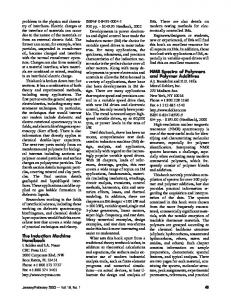
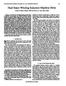
As illustrated in Fig. 1, a resistor RFe coupled to the magnetizing branch is added to incorporate iron losses. This resistor can be used to take into account core losses in stator iron. The equations that describe the induction machine model can be conveniently expressed in synchronous reference frame by [4,8]:
1067
is Rs
RRLr
|
(oL,yrr
VSS
rrA}
Fig. 1. Equivalent circuit of an induction machine by considering iron losses
Ro I + - -
VS
Lm
)s=LosIs +$m Dr = L(yr r + 4Dm
,
LIr
Rr
+R~sI +Ir,t)^@L]1t Ir jQ)sLcr ir + RFr (is +)
joL
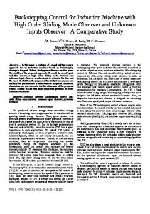
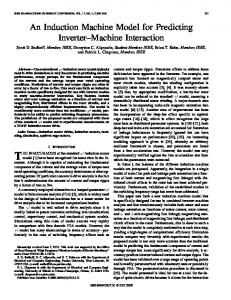
Fig.2. Modified equivalent circuit by considering iron losses
the relationships between the flux linkages and ~~~~~~~~~Using currents, and introducing, (8) into the equations (1-2), the machine equations in terms of space vectors, in a synchronous reference frame, that includes iron loss can be
dO +rS (1) dt -
d(tDr j2 I +l r Fr
LGS
~~~~~~~~~induction F1
(2) obtained-as:
$m=LmIm
(3)dR
Im+IFe=Is+Ir
(4)
s~~~~~~~~~~~~~~~~~~~~~~~~~
RFeIFe = mdt +J)sLmIm Tem =P Ln [Fdr(Iqs IqFey-cFqr(Ids 'dFe)]
-
dt
y
w1
dt(10
d(+m) jc) ) dt . = Rs l + LGS dt +KL +;(ISLGSIS + (iSLM + RFS)(IS + Ir)
()Vr =Rrlr +Lrjr -t+ [L~~jRFrsl
(9)
d(ts+10)
+j(WsiLGrIr + (jWSJlLM + RFr)(Is + 'r)
(6)
The symbols Is, Ir denote the stator and rotor currents, Knowing that generally RFe y onsLm the serial mutual respectively, Vs, Vr stator and rotor voltages. (tsA(tr and (tm are inductance LM is given by: stator, rotor and airgap flux linkages in two axis rotational (d-q) reference frame. RS, Rr are stator and rotor resistance and L R Fe Lgyr LGr,Lm are stator, rotor leakage inductances and LMt2er 2 oLm (11) fs2p + ( respectively. m(m+ The reference frame, the (4)s r Fe +rame, magnetizing(=LI inductance, Lm o(, as Symbol rotor and the slip speeds are denoted Or and a P represents the number of pole-pairs, and Tern is the RFS and RF. are, respectively, equivalent serial resistances electromagnetic torque. Fe is the index associated to iron loss associated to stator and rotor that are given by: branch. =(I Im of ~ + ~ ~to an ~ increase ~ ~~~~~~~~~V Lcyr (8)+L _j~(I Consideration iron loss~ leads of Rre the system order and introduces additional mutual coupling between the R Lm2 RFe _d_I_Lm2_ r2 d2 axis components d and q. To reduce the system order, the (1) RFV s ()m- Lm2 c 9Fe equivalent circuit of Figure.1 can be transformed from the RFe +d Lm parallel to aserial form [6]. Substituting (5) into (4) gives: (13) RFr= Rsl +,Lm 2R ,
In addition we have: It is assumed that the rate of change of 'm is small compared with the terms in (7). Hence, equation (7) can be writing as: mFe R
FeO=LL m'dt+Irj
The-symbolsIs,I denote
RFS - RFr = s
(8)
thestatorandrotorcuents
Isl
Cs)5 Lm2 RFe RFe2 + )s2Lm
< 05 Lm RF