IEEE TRANSACTIONS ON INDUSTRY APPLICATIONS, VOL. 39, NO. 6, NOVEMBER/DECEMBER 2003
1681
Modeling of a Linear PM Machine Including Magnetic Saturation and End Effects: Maximum Force-to-Current Ratio Henk Polinder, Member, IEEE, Johannes G. Slootweg, Member, IEEE, Martin J. Hoeijmakers, Member, IEEE, and John C. Compter
Abstract—The use of linear permanent-magnet (PM) actuators increases in a wide variety of applications because of their high force density, robustness, and accuracy. These linear PM motors are often heavily loaded during short intervals of high acceleration, so that magnetic saturation occurs. This paper models saturation and end effects in linear PM motors using magnetic circuit models. The saturating parts of the magnetic circuit are modeled as nonlinear reluctances. Magnetomotive forces represent the currents and the magnets. This paper shows that when saturated, a negative -axis current increases the force developed by the motor. Although the increase is not large, it is nevertheless useful, because a negative -axis current also results in a decrease in the amplifier rating. Further, the trajectory for the maximum force-to-current ratio is derived. The correlation between the calculated and the measured force justifies the model. Index Terms—Linear actuator, magnetic circuit modeling, maximum force-to-current ratio, permanent-magnet (PM) motor, saturation.
I. INTRODUCTION
A
TREND to increase the use of linear electromechanic actuators can be observed in a wide range of applications, from airplanes (fly by wire) to factory automation [1]–[3]. Important advantages of linear electromechanical actuators are that they are clean, robust, and efficient and that they can be fed from simple copper wires. Further, direct-drive actuators can have a high positioning and speed accuracy because no mechanical transmission is necessary. For demanding applications, the linear motors are mostly of the permanent-magnet (PM) type, because compared to other linear electric motors, they have a high force density, a high efficiency, and a relatively simple control. This paper deals with a linear PM motor applied to horizontal micrometer positioning in wafer steppers and component placing machines. To control such a system accurately and with a highPaper IPCSD 03–094, presented at the 2003 IEEE International Electric Machines and Drives Conference, Madison, WI, June 1–4, and approved for publication in the IEEE TRANSACTIONS ON INDUSTRY APPLICATIONS by the Electric Machines Committee of the IEEE Industry Applications Society. Manuscript submitted for review April 2, 2003 and released for publication August 11, 2003. H. Polinder and M. J. Hoeijmakers are with Electrical Power Processing, Delft University of Technology, 2628 CD Delft, The Netherlands (e-mail:
[email protected];
[email protected]). J. G. Slootweg is with Electrical Power Systems, Delft University of Technology, 2628 CD Delft, The Netherlands (e-mail:
[email protected]). J. C. Compter is with Eindhoven University of Technology, 5600 MB Eindhoven, The Netherlands (e-mail:
[email protected]). Digital Object Identifier 10.1109/TIA.2003.819010
performance, classical feedback control systems are not suitable because they make forces based on position errors, which implies the presence of these position errors. Instead, feedback control should be combined with feedforward control [4], where all available information about the system is used to prevent errors. For example, information about moving masses and the desired position and speed profiles is used to calculate the force necessary to obtain the desired position and speed profile. In this case, the feedback controller only has to eliminate errors due to unpredictable phenomena. Therefore, a good feedforward control must be able to predict the force developed by the motor. When the currents are low, the motor does not saturate and the force is well predictable as linearly proportional to the current. However, during short intervals of large acceleration, the currents are so high that the magnetic circuit saturates, and the force is not easily predictable, which complicates the control. Therefore, the goal of this paper is to model the motor in such a way that the force generated by the linear motor can be predicted as a function of the current and the position. This model is used to maximize the force-to-current ratio. To investigate end effects, two modes are compared, one neglecting, and the other incorporating end effects. For interior PM motors, using negative -axis currents to maximize the force-to-current ratio is common practice [5]–[11]. In these machines, a negative -axis current results in an additional force because of the reluctance effect. A maximum thrust per amp trajectory for linear interior PM motors is derived in [6]. Saturation is included for rotating motors in [7] and for linear motors in [8]. However, [7], [10], and [11] state that maximum torque (or force) to current control in motors with surface-mounted PMs is achieved when the -axis current is kept zero, or in other words when the angle between the no-load voltage and the current is kept zero. This statement is true for motors which are not heavily loaded so that saturation is negligible. However, this paper investigates the effect of a negative -axis current on the force when saturation occurs and concludes differently. Besides, negative -axis currents are used to extend the speed range of PM machines, which is mostly referred to as flux weakening [6], [8]–[11]. This is mostly applied in PM machines with interior magnets; in machines with surface-mounted magnets, the increase in the speed range is limited [11]. However, in a motor with surface magnets, adding a negative -axis current as well results in a reduction of the volt-ampere rating of the amplifier or the inverter [10], [11]. This effect is useful in our application.
0093-9994/03$17.00 © 2003 IEEE
1682
IEEE TRANSACTIONS ON INDUSTRY APPLICATIONS, VOL. 39, NO. 6, NOVEMBER/DECEMBER 2003
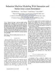
in Fig. 3, this voltage is almost sinusoidal due to the chosen magnet width and the skewing of the magnets. Fig. 3 also gives the no-load flux linkages, obtained from integrating the no-load voltages. A position sensor detects the position of the translator. Based on this position information, a power amplifier generates a three-phase sinusoidal current. III. MAGNETIC CIRCUIT MODELING A. Equivalent Magnetic Circuit Model Fig. 1. Photograph of the linear PM machine with magnets on a bottom plate and a translator with coils.
Furthermore, negative -axis currents are used to minimize the sum of the core losses and the copper losses in PM machines [12], [13]. However, in linear motors, the core losses are mostly small compared to the copper losses because of the relatively low speeds, so that this effect is not important. It is possible to calculate the motor force using finite-element methods [14]. Here, we use a magnetic circuit model, like in [15] and [16]. An important advantage of finite-element methods compared to a magnetic circuit model is the possibility to calculate cogging forces. However, the linear machine under investigation has been designed for minimum cogging by the choice of the geometry of the teeth, the end teeth and the skewed magnets, resulting in a cogging force in the order of 1% of the maximum force. This paper mainly focuses on the forces at high current levels where cogging is negligible. Magnetic circuit models are used because with these models, trends can be observed faster and because they can be used easier in optimization programs, for example, to search for maximum force-to-current ratio trajectories. Magnetomotive forces represent the currents and the magnets. The saturating parts of the magnetic circuit are modeled as nonlinear reluctances. This paper first characterizes the investigated motor. Then, it describes the magnetic circuit modeling of the motor and gives expressions for voltages and forces. Subsequently, calculated and measured results are given and compared to validate the model. Finally, conclusions are drawn.
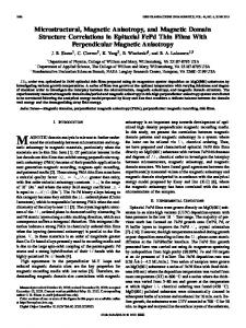
In this section, two magnetic circuit models of the linear motor are derived. In these models, the fluxes in the teeth are the most important variables, because these fluxes link with the translator coils and are used for the calculation of the force. Fig. 4 depicts the first magnetic circuit model of the motor. In this model, it is assumed that only the translator teeth (around which the coils are wound) and the translator yoke saturate. Because the flux density in the back iron is lower, the reluctance of the back iron is neglected. In order to obtain the second, further simplified model of Fig. 5, the yoke reluctance, end effects and end teeth are neglected in such a way that the machine is modeled as if it were infinitely long or as if it were a cylindrical motor. Also the reluctance of the translator yoke is neglected. In this case, it is sufficient to consider three translator teeth. B. Reluctance Values A general expression for the value of a reluctance is (1) where magnetic field intensity in the circuit; magnetic flux density in the circuit; length of the magnetic circuit; cross section of the magnetic circuit. (the reluctance With this equation, the air-gap reluctance between a tooth and the back iron) can be expressed as (2)
II. MOTOR DESCRIPTION Fig. 1 is a photograph of the linear PM motor; Fig. 2 depicts a schematic section. Table I lists some important dimensions. The magnets are on the bottom plate. The translator has a fractional pitch winding with the following advantages. • The winding consists of coils around a tooth with simple short end windings that can be wound outside the motor. • The orthocyclic method of coil winding described by Lenders [17] can be used, which results in a high copper filling factor of the slots and a good heat transfer from the coils to the back iron. • The translator yoke and the back iron behind the magnets can be thin compared to machines with larger pole pitches and full-pitch windings [1]. In Fig. 2, a phase consists of four series-connected coils. When the translator moves over the magnets, a three-phase voltage is induced in the star-connected phases. As shown
where Carter factor [18]; air-gap length; magnet length in the magnetization direction; relative magnetic permeability of the magnets; magnetic permeability in vacuum; slot width; tooth width; stack length, the length in the direction perpendicular to the plane of the drawing in Fig. 2. In this equation, the width of the flux path is taken as the tooth pitch (tooth width plus slot width) because the flux crosses the air gap over the whole tooth pitch due to flux fringing. The average path length of the flux path is the air-gap length multiplied by the Carter factor, which takes into account that the fringing flux follows a longer path [18].
POLINDER et al.: MODELING OF A LINEAR PM MACHINE INCLUDING MAGNETIC SATURATION AND END EFFECTS
1683
Fig. 2. Section of the linear PM motor with some dimensions.
C. Magnetomotive Forces
TABLE I PM MOTOR DIMENSIONS
The magnetomotive force of a translator current equals the phase current multiplied by the number of turns of the coil around a translator tooth . The magnets also cause a flux in the translator teeth. This flux is determined from the measured no-load voltage of Fig. 3. The flux varies sinusoidally, as can be concluded from the sinusoidal form of the no-load voltages. Hence, the fluxes in the translator teeth due to the magnets are given by
(7)
Fig. 3. Measured no-load phase voltages and flux linkages; the speed is not constant.
The slot leakage reluctance
is calculated as
where is the translator position, which is zero in Fig. 2. This flux follows a path different from the path followed by the flux caused by the translator currents and the reluctance is different from the air-gap reluctance. However, for our model, the flux in the translator teeth is of interest. Therefore, the magnetomotive force of the magnets is modeled as
(3) is the slot height. where The factor 2 in this equation takes into account that the slot leakage flux density increases linearly from zero close to the yoke to a maximum close to the air gap. The starting point for the determination of the tooth reluccurve of the magnetic material [19] tance is the measured curve is approximated with a as depicted in Fig. 6. This function also depicted in Fig. 6
(8) In no load, these magnetomotive forces result in the fluxes of (7), because saturation is negligible and therefore the tooth and yoke reluctances are negligible. When the teeth saturate, the fluxes caused by the magnets decrease, but the magnetomotive forces remain unchanged. IV. VOLTAGE EQUATIONS AND FORCES
(4) If we use this expression in the general expression for a relucas tance, we obtain the tooth reluctance
A. Voltage Equations The voltages of the translator phases can be written as
(5) In this equation, the circuit surface is the cross section of a tooth, and the length is taken as two-thirds of the tooth height, because leakage flux enters the tooth over the whole height, so that the lower part does not saturate. as In the same way, we obtain the yoke reluctance (6) where
is the translator yoke height.
(9) where phase resistance; phase current of phase ; flux linkage of phase ; flux in the th tooth of phase ; number of turns around a tooth.
1684
Fig. 4.
IEEE TRANSACTIONS ON INDUSTRY APPLICATIONS, VOL. 39, NO. 6, NOVEMBER/DECEMBER 2003
Magnetic circuit model of the linear PM motor including end effects.
B. Force Calculations The power amplifier generates a three-phase current, which is made a function of the position
(11) where the current leads the no-load voltage with an angle , compare (10). If the currents are so low that the teeth do not saturate, the electromagnetic force can be calculated from the no-load voltages and currents [18] as Fig. 5. Simplified magnetic circuit model of the linear PM motor neglecting end effects.
(12) Under saturated conditions, the electromagnetic force is cal[16], [20] as culated from the coenergy (13) The coenergy is calculated [16], [20] as
Fig. 6. Measured BH curve of the magnetic material (+) and the approximation used in the calculations.
(14) is the coenergy when the currents are zero. where is not a function of because the It is assumed that cogging force is negligible.
The no-load voltages are given by
V. CALCULATED AND EXPERIMENTAL RESULTS A. Force as a Function of Position and End Effects (10) Because some elements in the magnetic circuit are nonlinear due to saturation, the equations for the fluxes have to be solved by means of an iteration process.
The force generated by the motor was measured as a function of the position and the current amplitude , while the angle was kept zero. Current amplitudes up to 15 A were used, which is three times the rated continuous current. Fig. 7 depicts the force calculated with the magnetic circuit of Fig. 5 neglecting end effects. Fig. 8 depicts the force calcu-
POLINDER et al.: MODELING OF A LINEAR PM MACHINE INCLUDING MAGNETIC SATURATION AND END EFFECTS
Fig. 7. Calculated force as a function of current amplitude and position neglecting end effects.
Fig. 8. Calculated force as a function of current amplitude and position considering end effects.
lated with the magnetic circuit of Fig. 4 considering end effects. Fig. 9 depicts the measured force. Fig. 10 combines measurements and calculations. For current amplitudes up to about 7 A, the force increases linearly with the current, but at larger current amplitudes, the force increases less due to saturation. If end effects are neglected, the force at high currents is periodic every 4 mm, because every 4 mm the same magnetic configuration comes back. If end effects are considered, an additional periodicity of the force arises every 12 mm, which is a pole pitch. In the measurements, both periodicities are present. It appears that the model including end effects exaggerates the periodicities, but the trends are clearly visible. B. Maximum Force-to-Current Ratio For the force calculations in this section, the magnetic circuit of the motor neglecting end effects of Fig. 5 has been used. The force generated by the motor was measured while the translator was kept in one position as a function of the current amplitude hat and the angle , both introduced in (11).
Fig. 9.
1685
Measured force as a function of current amplitude and position.
Fig. 10. Calculated force neglecting (…) and considering (-) end effects and measured (+) force as a function of position at three different current amplitudes.
Figs. 11 and 12 depict the force as a function of the angle for different current amplitudes in two different positions. For low current amplitudes, the force as a function of the phase angle is cosinusoidal, as expected from the linear model (12). However, for larger current amplitudes, the form of the force changes: the force is larger when the current leads the no-load voltage, . especially in the position To check the validity of this conclusion, Fig. 13 depicts the calculated force as a function of the current amplitude for two . The force generated values of the angle at position is about 3% higher with a current amplitude of 15 A at . than the force generated with the same current at Figs. 14 and 15 depict the contour plot of the measured and plane in two different pothe calculated force in the sitions. Also the trajectory for maximum force-to-current ratio has been depicted. Again, the correlation between the trends of the calculated and measured contour plots of the force is rather good. In both positions, the maximum force-to-current ratio in saturation is obtained with a negative -axis current. However,
1686
IEEE TRANSACTIONS ON INDUSTRY APPLICATIONS, VOL. 39, NO. 6, NOVEMBER/DECEMBER 2003
Fig. 11. Force as a function of angle at different current amplitudes in position x = 0.
Fig. 14. Trajectory for maximum force-to-current ratio in a set of contour plots i plane at position x = 0. -: calculated; …: measured. of the force in the i
0
Fig. 12. Force as a function of angle at different current amplitudes in position x = 2 mm.
Fig. 15. Trajectory for maximum force-to-current ratio in a set of contour plots of the force in the i i plane at position x = 2 mm. -: calculated; …: measured.
0
Fig. 13.
Force as a function of current amplitude and angle at x = 0.
in position , the optimum negative -axis current is sigmm. nificantly larger than in position
Fig. 16 depicts the calculated angle for maximum force-tocurrent ratio as a function of position and current amplitude. The information of this picture can be incorporated in a control system. If this is too complicated, a strategy could be to work with a constant average angle of, for example, 10 . It can be concluded that using a negative -axis current increases the force in saturation. This effect can be explained from the fact that a negative -axis current reduces the flux levels in the teeth, thus reducing the saturation level, while the -axis current hardly decreases when the current amplitude remains constant.
POLINDER et al.: MODELING OF A LINEAR PM MACHINE INCLUDING MAGNETIC SATURATION AND END EFFECTS
Fig. 16. Angle ' for maximum force-to-current ratio as a function of position and current.
The correlation between measurements and calculations is reasonable. Because of the rather rough magnetic circuit modeling, very accurate results cannot be expected. However, both the measured and the calculated results confirm the conclusion that in a saturated machine, the force can be increased by using a negative -axis current. Although this increase is not large, it is useful as well, because it results in a decrease in the terminal voltage, and therefore of the amplifier rating. VI. CONCLUSION This paper has shown that it is possible to model a linear permanent-magnet motor including saturation using magnetic circuit theory. In saturated condition, the force becomes a function of the position, where end effects are not negligible. In saturation, a negative -axis current results in an increase in the generated force, as appears from measurements as well as from calculations. Although the increase is not large, it is nevertheless useful, because a negative -axis current also results in a decrease in the amplifier rating. The trajectory for maximum force-to-current ratio is different for different positions. The correlation between the calculated and the measured force justifies the model. ACKNOWLEDGMENT The authors thank A. T. A. Peijnenburg, Philips CFT, Eindhoven, The Netherlands, for providing them with the linear PM motor for the experimental work.
1687
[6] M. Sanada, S. Morimoto, and Y. Takeda, “Interior permanent magnet linear synchronous motor for high-performance drives,” IEEE Trans. Ind. Applicat., vol. 33, pp. 966–972, July/Aug. 1997. [7] C. Mademlis and V. G. Agelidis, “On considering magnetic saturation with maximum torque to current control in interior permanent magnet synchronous motor drives,” IEEE Trans. Energy Conversion, vol. 16, pp. 246–252, Sept. 2001. [8] G. Hong, X. Qiang, and J. Zhenchun, “Effects and compensation of magnetic saturation in flux-weakening controlled interior permanent magnet linear synchronous motor,” in Proc. Fifth Inte. Conf. Electrical Machines and Systems, vol. 2, Beijing, China, 2001, pp. 913–916. [9] B. J. Chalmers, L. Musaba, and D. F. Gosden, “Variable-frequency synchronous motor drives for electric vehicles,” IEEE Trans. Ind. Applicat., vol. 32, pp. 896–903, July/Aug. 1996. [10] N. Bianchi and S. Bolognani, “Parameters and volt-ampere ratings of synchronous motor drive for flux-weakening applications,” IEEE Trans. Power Electron., vol. 12, pp. 895–903, Sept. 1997. [11] S. Morimoto, Y. Takeda, T. Hirasa, and K. Taniguchi, “Expansion of operating limits for permanent magnet motor by current vector control considering inverter capacity,” IEEE Trans. Ind. Applicat., vol. 26, pp. 866–871, Sept./Oct. 1990. [12] S. Morimoto, M. Sanada, and Y. Takeda, “Loss minimization control of permanent magnet synchronous motor drives,” IEEE Trans. Ind. Electron., vol. 41, pp. 511–517, Oct. 1994. [13] R. S. Colby and D. W. Novotny, “Efficient operation of surface-mounted pm synchronous motors,” IEEE Trans. Ind. Applicat., vol. 23, pp. 1048–1054, Nov./Dec. 1987. [14] M. Platen and G. Henneberger, “Examination of leakage and end effects in a linear synchronous motor for vertical transportation by means of finite element computation,” IEEE Trans. Magn., vol. 37, pp. 3640–3643, Sept. 2001. [15] V. Ostovic, J. M. Miller, V. K. Grag, R. D. Schultz, and S. H. Swales, “A magnetic-equivalent-circuit-based performance computation of a Lundell alternator,” IEEE Trans. Ind. Applicat., vol. 35, pp. 825–830, July/Aug. 1999. [16] H. Polinder, J. G. Slootweg, J. C. Compter, and M. J. Hoeijmakers, “Modeling a linear PM motor including magnetic saturation,” in Proc. IEE Int. Conf. Power Electronics, Machines and Drives, Bath, U.K., 2002, pp. 632–637. [17] W. Lenders, “The orthocyclic method of coil winding,” Philips Tech. Rev., vol. 23, pp. 365–404, 1961/1962. [18] R. Richter, Elektrische Maschinen, Erster Band, 3rd ed. Basel, Switzerland: Birkhäuser, 1967. [19] J. Jansen, “Materials library,” Philips N.V., Eindhoven, The Netherlands, Rep. CTR505-90-RJ261, 3rd ed., 1990. [20] A. E. Fitzgerald, C. Kingsley, and S. D. Umans, Electric Machinery, 6th ed. London, U.K.: McGraw-Hill, 2002.
Henk Polinder (M’97) received the M.Sc. and Ph.D. degrees in electrical engineering from Delft University of Technology, Delft, The Netherlands, in 1992 and 1998, respectively Since 1996, he has been an Assistant Professor in the Electrical Power Processing group at Delft University of Technology. In the summer of 2002, he spent a few months at the University of Newcastle-upon-Tyne, U.K. He is mainly interested in design aspects of special electrical machines for renewable energy applications (wind and wave energy) and for mechatronic applications.
REFERENCES [1] J. F. Gieras and Z. J. Piech, Linear Synchronous Motors: Transportation and Automation Systems. Boca Raton, FL: CRC Press, 2000. [2] I. Boldea and S. A. Nasar, Linear Electric Actuators and Generators. Cambridge, U.K.: Cambridge Univ. Press, 1997. [3] H.-D. Stölting and E. Kallenbach, Handbuch Elektrische Kleinantriebe. Munich, Germany: Hanser, 2001. [4] N. Mohan, Electric Drives, an Integrative Approach. Minneapolis, MN: NMPERE, 2001. [5] S. A. Nasar, I. Boldea, and L. E. Unnewehr, Permanent Magnet, Reluctance and Self-Synchronous Motors. Boca Raton, FL: CRC Press, 1993.
Johannes G. (Han) Slootweg (M’01) received the M.Sc. degree in electrical engineering (cum laude) in 1998 from Delft University of Technology, Delft, The Netherlands, where he is currently working toward the Ph.D. degree on the effects of large-scale integration of wind power on power system dynamics in the Electrical Power Systems Laboratory. During his studies, he stayed in Berlin, Germany, for six months, to attend lectures at TU Berlin and to conduct research at the Dynamowerk of Siemens AG.
1688
IEEE TRANSACTIONS ON INDUSTRY APPLICATIONS, VOL. 39, NO. 6, NOVEMBER/DECEMBER 2003
Martin J. Hoeijmakers (M’80) was born in Geertruidenberg, The Netherlands, in 1956. He received the M.Sc. and Ph.D. degrees in electrical engineering from Eindhoven University of Technology, Eindhoven, The Netherlands, in 1980 and 1984, respectively. From 1984 to 1991, he was an Assistant/Associate Professor at Eindhoven University of Technology. Since 1991, he has been an Associate Professor at Delft University of Technology, Delft, The Netherlands. He was a Consultant for the Netherlands Energy Research Foundation (ECN) and for NedWind Rhenen. From 1989 to 1991, he worked part-time at the Netherlands Energy Research Foundation. Since 1999, he has been a part-time business associate in EMechForce, an engineering company that specializes in consulting and implementation services in electromechanics and electrical drive systems. His main research interests are traction drive systems, especially the electrical variable transmission. Dr. Hoeijmakers received the Hidde Nyland Award in 1996 for his contributions to electrical power engineering.
John C. Compter received the M.S.E.E. degree from Delft University of Technology, Delft, The Netherlands, in 1976, and the Ph.D. degree from Eindhoven University of Technology, Eindhoven, The Netherlands, in 1984. He joined the Philips Research Laboratories in 1978, following military service. His involvement in projects, directed to electrical drives in equipment and products, was the basis for his dissertation, “Microprocessor controlled reluctance motor.” He was with Philips Domestic Appliances as Group Leader, Electrical Development, from 1984 till 1990. He then joined the Philips Center for Industrial Technology (CFT), Eindhoven, The Netherlands, as Senior Consultant, Electrical Drives. In 2002, he joined the Department of Mechanical Engineering, Eindhoven University of Technology, as an Adjunct Professor. His interests are in the areas of electromechanical drives and magnetic components for semiconductor production equipment and for all kinds of domestic applications. His resulting innovative proposals are described in several patents.