13, No. 1, March 1998. 15. INDUCTION MOTOR DYNAMIC AND STATIC INDUCTANCE. IDENTIFICATION USING A BROADBAND EXCITATION TECHNIQUE.
IEEE Transactions on Energy Conversion, Vol. 13, No. 1, March 1998
15
INDUCTION MOTOR DYNAMIC AND STATIC INDUCTANCE IDENTIFICATION USING A BROADBAND EXCITATION TECHNIQUE A. GANJI*, P. GUILLAUME**,member IEEE R. PINTELON**,member IEEE P. LATAIRE* *Vrije Universiteit Brussel, Department E E C , Pleinlaani 2, 1050 Brussels (Belgium) U
Vrije Universiteit Brussel, Department ELEC, Pleinlaan 2, 1050Brussels (Belgium)
Abstract-The performance of indirect vector control depends upon accurate prediction of the motor slip angular frequency (a)for the demand torque. The required slip gain depends upon the rotor time constant of the motor (Tr).This value varies significantly over the operating temperature range and saturation level of a typical motor. This variation, if not compensated for, results in a significant degradation in torque production from a vector control system. The saturation effect can be compensated by an adaptive flux model if precise knowledge of the induction motor magnetizing curve is available. The aim of this paper is to present the application of an advanced system identification methodology enabling the offline estimation of the magnetizing curve (dynamic and static inductance) of induction motors.
The identification of an induction motor parameters can be implemented as an on-line or off-line procedure. As the change in temperature is slow, the change in rotor resistance is also slow, and it is possible to perform on-line closed-loop adaptation [SI. But saturation in a machine can change very quickly, and the corresponding change in rotor inductance should be calmpensated by an adaptive flux model in openloop [12]. Application of an adaptive flux model requires precise knowledge of the induction motor magnetizing curve. The aim of this paper is to present the application of a broadband excitation technique for standstill identification of the induction motor rotor dynamic and static inductance with regard to dependencies on saturation. 11. BROADBAND EXCITATIONS
I. INTRODUCTION To develop the high performance vector control scheme, precise information is required about the rotor flux vector, which serves as a reference for decoupling the torque and flux producing currents. In indirect vector control, the rotor flux vector is estimated from the stator currents and the rotor speed. However the performance of this method depends upon predicting accurately the motor slip frequency (fJ for the demand torque. The required slip gain depends upon the rotor time constant of the motor (T,) which is determined by means of the rotor inductance (Lr) and the rotor resistance (RJ from the equation Tr = L,/ R. This value varies significantly over the operating temperature range and saturation level of a typical motor. This variation, if not compensated for, results in a significant degradation in torque production from a vector control system. The influence of incorrect rotor time constant on rotor flux estimation has been fully investigated in the literature and we will not go into that further.
PE-131-EC-01-04-1997 A paper recommended and approved by the IEEE Electric Machinery Committee of the IEEE Power Engineering Society for publication in the IEEE Transactions on Energy Conversion. Manuscript submitted January 30, 1996; made available for printing March 26, 1997.
The Stand Still Frequency Response (SSFR) has been widely used to identify the electrical machine parameters [6, 7, 15, 18, 191. However, this procedure takes a very long time to complete when using stepped sine and the systems with large time constants. To eliminate this shortcoming, the broadband excitations have been developed, injecting multiple frequencies at the same time. Next, the maximum likelihood estimator, ELiS (Estimation of Linear time invariant Systems), is employed to estimate the transfer function coeffficients of the motor from the frequency domain data. The validity of this technique has already been verified in several alpplications [l, 141. Based on reference [14], a Frequency Domain System Identification Toolbox has been written, as a module fair use with MATLAB'" [ll]. The toolkit contains specialized tools €or the identification of linear dynamic systems from measurements of the excitation and the response signals. ELiS takes into account the noise on all measurements and generates automatically the starting values. The reader is referred to [l, 11, 141 for a thorough discussion of the application of the broadband excitation technique and the system identification methodology. III. smw OF THE TEST
The basic configuration of the test setup on an induction machine is shown in Fig. 1. The objective is to inject a multifrequency signal using an arbitary waveform generator
0885-8969/98/$10.00 0 1997 IEEE
Authorized licensed use limited to: Rik Pintelon. Downloaded on December 5, 2008 at 09:14 from IEEE Xplore. Restrictions apply.
16 synchro
clock
Fig. 2. Induction motor equivalent circuit based on rotor flux.
motor windings Fig. 1. Experimental setup of control and signal processing loops.
to the set point of a thyristor rectifier, which serves as an amplifier, in order to apply larger signals to the motor. The rectifier can only deliver positive currents. The multisine waveform is therefore superimposed on a dc current, in such a manner that the sum of the two is always larger than a minimum value. This minimum should be sufficiently high to avoid intermittent conduction of the rectifier. The multisine superimposed on a dc level, enables the algorithm to identify the dynamic inductance of the machine. The dc current level is chosen to adjust the magnetic saturation level in the stator windings of the machine. Therefore, the measurements are made at the actual magnetizing current of the motor. In the final industrial application the rectifiers' task would be performed by the PWM power electronic converter which drives the motor at variable speed by feeding variable frequency currents. The multisine s(t) is a periodic signal consisting of a sum of harmonically related frequencies:
with ik an integer and T being the basic period of the multisine. The amplitudes Ak are chosen proportional to the desired amplitude spectrum in order to maximize the signalto-noise ratio of the measurements. By a proper selection of (Dkit is possible to reduce the crest factor of the signal. This will allow a maximum energy injection in the system for a specified maximum peak value of the excitation signal. The frequencies are chosen in the band [0.1 Hz to 98 Hz] and 100 selected frequencies are picked up. This results in significant data reduction and improved signal-to-noise ratio. Finally, the transfer function of the induction motor (motor impedance) is identified from current and voltage measurements. IV. INDUCTION MACHINE MODEL The model of the induction motor which is used for the identification algorithm is shown in Fig. 2.
It is assumed that the motor is symmetric and the skin effect, the magnetic hysteresis and the iron losses are neglected. In Fig. 2: L,= mutual inductance, R, and R, = stator and rotor resistance, a = Lr
:L and s i s the , CT = 1- LsLr
slip. Since during the test procedure the rotor is at standstill, the slip will be equal to one for all frequencies. According to Fig. 2. the transfer function of the motor is a 2/1 order rational function in the Laplace domain: Z = a2p' + alp + a0 , = jo blP + bo
The relations between the parameters of the equivalent circuit, shown in Fig. 2, and the coefficients of (2) are as follows: 1= bo (3) T,= bl (4) R, = 0.5(% / 2) (5) oL, = 0.5(a, / bl) (6) aLm= 0.5(al - %bl - a2 / bl) (7)
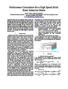
V. DEFINITION OF THE DYNAMIC AND STATIC INDUCTANCE By definition, two kinds of motor inductance are considered in the literature [8, 13, 171: 1) The static inductance (SL) is the slope of the straight line (OA) from the origin through the actual operating point A on the magnetizing curve (Fig. 3). The static inductance is therefore the division of the flux by the magnetizing current SL =-
a)
I,
(9)
This value is used for steady state condition or when operation of the machine changes from one to another steady state situation and the transients are not so important. 2) The dynamic inductance (DL) is the slope of the tangent line (AC), to the magnetizing curve at the same operating point A, as represented in Fig. 3. Thus: d@
DL =dIm
(10)
17
mathematical model for, respectively, the magnetizing curve and the static inductance. Since this will introduce model errors, a uadeoff between variance and bias has to be made.
0
VI. MATHEMATICAL MODELING OF THE MAGNETIZING CURVE
B A0
C
Ll
D
Alm=lm
Fig. 3. Definition of the static and dynamic inductance.
This parameter should be used when the dynamic behavior of the machine is considered under transient conditions. The shape of the static and dynamic curves depends on the mathematical model which has been employed for the magnetizing curve of the machine. These inductances are illustrated in Fig. 4 using the tangent hyperbolic model as a mathematical function for the magnetizing curve [4,8, 161.
L
J
In practice, the magnetkzing function of a machine is very difficult to formulate madhematically. Several authors have proposed different methods to develop formulas representing the flux andl magnetizing current relation (magnetizing curve). The following models are mostly considered in the literature: -Arctangent model [4, 161:
2
with CDs and I, being the saturated flux and nominal magnetizing current respectively. - Tangent hyperbolic model [4,8, 161:
- Static inductance SL,=a/l,
with the same definitions for Qsand I,. An exponential model foir the static inductance [2,4, 131:
-
ec
Dynamic inductance-\ DL, = 6Idl,
Im
Fig. 4. Corresponding static and dynamic inductance of Fig. 3.
ec'
where A,B,C,D depend on the inductance at zero magnetizing current and the shape of the inductance function. E represents the saturated inductance. This model rakes into account the low level iron nonlinearity. - A rational model for the static inductance [3,9, 101:
The relation between SL and DL can be obtained from the following equation:
(15)
+ SL
DL =*I, d1m
It follows from the forgoing discussion that the dynamic inductance of an induction motor can be obtained by solving equations (10) or (11). In both cases the differentiation of the static inductance or the magnetizing curve is inevitable. The static inductance of a machine can be easily obtained from the classical noload test. However, in this method the obtained inductance would be a set of discrete noisy data. Taking derivatives from a set of discrete noisy data by numerical methods normally results in large errors. The uncertainty is significantly reduced by analytic differentiation of the magnetizing curve, using equation (lo), or of the machine static inductance function, using equation (1l).This requires a
with L1 , Lo and Ls being the unsaturated inductance, the inductance at nominal operating point and the saturated inductance respectively. a is the saturation index and is typically in the range of 5 5 a 5 9. Fig. 5 illustrates the opDimized curves of a noload test using different ma~ematicalmlodels. It should be noted that all proposed formulas may have sufficient accuracy to express a static inducitance model. However, where the dynamic inductance is concerned, the deviation between the dynamic models becomes important. It is shown in Fig. 5 that, in spite of agreement between all the proposed static models, the differences between the dynamic models are large.
Authorized licensed use limited to: Rik Pintelon. Downloaded on December 5, 2008 at 09:14 from IEEE Xplore. Restrictions apply.
18
I. ."--------{ .......-. .......
5o
-...
a
. ._ **-.. ---..2
....-,.
,
n V
b
0
0.5
1
1.5
I
I
I
2
lIml= J2Inl-meas.surd
50 n
0.5
U
0
loo] d
modulus of the magnetizing current [17]. Since the results of the broadband excitation are compared to the classical noload test, the measured magnetizing currents of the two tests should be modified with the modulus of the magnetizing current in order to represent the same flux level. The modulus of the magnetizing current in the case of the noload test, using a 3 phase symmetric supply, is:
1
1.5
2
I
I
I
0.5
1
I
I
2
1.5
1
Ix = Ibe-measured 1 I =-(I J5 be-measwed
+0 )
2
* llml = -Ibe-measured &
with Ih.mew;ured the measured value of the current injected to the motor. Therefore, the measured currents of the broadband
Jz Js
excitation should be multiplied by a factor of -=0.816
50
to
represent the corresponding value of the noload test results.
U
0
being the measured value of the stator current. with In case of the broadband excitation (two phase excitation):
0.5
1
1.5
I,
(P.U.)
Fig. 5 . Comparison of different proposed models for SL (solid line) and DL (dashed line) and the noload test data (o),(a) :model (12), @) : model (U), (c) : model (14) and (d) : model (15) with a = 7.
In fact, as a consequence of differentiation, a small static error may result in a significant error in the dynamic inductance. It can be concluded, from the previous discussion, that calculation of the dynamic inductance of an induction machine from the static inductance by mathematical and/or by numerical methods is always problematic.
"0
0.5
1
1.5
2
3
2.5
1
VII. TEST RESULTS
The experimental results have been obtained from laboratory work based on the setup shown in Fig. 1. The setup consisted of a 19 KW cage induction motor (nominal magnetizing current 13.5 A) and a computer for design of the multisine signal as well as execution of the parameter estimation algorithm (ELiS). The broadband signal, which is generated by the VXI measurement system, is applied to the two stator terminals (R and S) when the machine is at standstill. The time domain data obtained by current measurements from values of multisine superimposed on a dc level and from terminal voltages. Current measurements are carried out with a Hall effect compensated transformer and voltage measurements are made with a differential amplifier. The time domain current and voltage data are then transformed to the frequency domain using the discrete Fourier Transform. The transfer function of the motor (2) is estimated by ELiS. Equations (5), (6) and (8) are used to obtain the motor parameters (stator resistance, total leakage and rotor inductance). The identified parameters are illustrated in Fig. 6. It should be noted that, the magnetizing inductance is defined as a division of the flux linkage modulus by the
0
0.5
1
1.5
2
I,@.u.)
Fig. 6. Comparison between broadband excitation test (0)and the noload test (solid line), (a) : rotor dynamc inductance, @) : total leakage and (c) : stator resistance.
It follows from Fig. 6 that, in spite of acceptable results for stator resistance and total leakage (OL,), rotor inductance errors can not be neglected. These errors are caused by a large estimation error of the stator resistance (the setup configuration introduces extra resistance to the device under test). The following section gives more explanation about stator resistance effects.
Influence of the stator resistance on the measured inductance The stator inductance measurements are very sensitive to the stator resistance. Table 1 illustrates this problem:
Authorized licensed use limited to: Rik Pintelon. Downloaded on December 5, 2008 at 09:14 from IEEE Xplore. Restrictions apply.
19 Table 1. Influence of the stator resistance on rotor inductance measurements.
Rs (d) 130 39
L, (mH)
140
150
160
170
180
35
30
26
22
19
A solutionfor stator resistance effect The stator resistance of an induction motor can be easily measured by a dc bridge. Therefore, it is not worthwhile to identify this item again, since this may deteriorate the estimation of other parameters. A promising solution for the stator resistance effect could be setting this parameter as a constant value in the motor transfer function (equation 5 and then in equation 2). However it is necessary to perform the broadband excitation test at the temperature at which the stator resistance is measured (or defined); otherwise errors may occur in the estimated rotor dynamic inductance. Fig. 7 illustrates the results of another test while the stator resistance was fixed to the 150 mQ (according to the motor data sheet).
It follows from Fig. 7-a that, as expected, there is a very good agreement between the identified rotor inductance from broadband excitation and the corresponding values obtained from the classical noload test. The accuracy of the identified dynamic rotor inductance: is sufficient to be implemented in vector controlled drives. Fig. 7-b shows that the rotor flux dependency on leakage inductance is negligible. This verifies the assumption which has been made in most of the practical applications (oL, = constant). However, in most of the practical applications the static inductance function is used as a flux model to compensate the saturation. Iit is necessary, therefore, to obtain this function from the broadband excitation technique. Since the dynamic inductance of the machine is identified by the broadband excitation, the static inductance function can be calculated using (11). The model (14) is chosen as an inductance model because of its better presentation of the inductance function. The results of the broadband excitation are then optimized by using standard optimization techniques (Least Squares technique) to find the mathematical model of the dynamic inductance. Equation 11 is used to obtain tlie static inductance function of the induction motor. Fig. 9 demonstrates the optimized dynamic inductance model in comparison with the broadband excitation data and the corresponding static inductance model compared to the noload test data.
a
0
0.5
1
1.5
2
"'or:
2.5
I
I
U
~~
0
"0
0.5
1
1.5
2
2.5
0.5
1
1.5
2
Im(P.U.)
Fig. 8. St&c and dynamic inductance idenhfied by broadband excitation, (a) : Identified dynammc inductance (0)and its optirmzed model (solid line) according to (14), and (b) : Obtained static model from equation 11 (0)compared to the noload test (solid h e ) .
It follows from Fig. 84) that the estimated static inductance function has sufficient accuracy to be employed as a flux model in ste,ady state vector controlled drives.
(TLdmH) 0 0
0.5
1
1.5
I,@.u.)
Fig. 7. Comparison between noload test (solid curve) and the broadband excitation (0)where R. = 150 mc2, (a): dynamic inductance and (b): total leakage.
VIIIL CONCLUSION The application of the broadband excitation technique to identify the induction motor parameters is tested. The results
obtained with the broadband excitation technique coincide
Authorized licensed use limited to: Rik Pintelon. Downloaded on December 5, 2008 at 09:14 from IEEE Xplore. Restrictions apply.
20
with that of the noload test. Static inductance of a machine can be easily obtained from noload test. However, calculation of the dynamic inductance is always confronted with large errors in analytical methods because of differentiation using (10) or (11). Therefor, precise and direct identification of this parameter is very important and this is the advantage of the proposed technique. However, the method should be tested for various rating of induction motors.
IX. REFERENCES: [l]Beya K., Pintelon R., Schoukens J., Lataire P., Guillume P., Mpanda-Mabwe B. and Delhaye M., "Identification of synchronous machines parameters using Broadband Excitation," IEEE Trans. or1 Energy Conversiors Vol. 9, No. 2, June 1994, pp. 270-280. [2] Bunt A. and Grotstollen H., "Parameter identification of an inverter-fed induction motor at standstill with a correlation method", Proceedings of EPE, 13-16 September 1993, Brighton, England, pp. 97-102. [3] De Jong €3. C. J., "Saturation in electrical machines", Proceeding of irttenurtional coilfererice on electrical rnachines, 1980, Athens, pp. 15451552. [4] Ficher J. and Moser U. H.,"Die nachbildung von magnetisierungskurven durch ein fache algebraishe d e r transzcndente funkionen", Arc/ziv f u r Elektrotechnik, Eingegangen am 25 Nov. 1955, pp. 286-298. [5] Ganji A. and Lataire P., "Rotor time constant identification of an induction motor in indirect vector controlled drives", Proceedings of EPE, 19-21 September 1995, Sevilla, Spain, Vol. 1, pp. 1.431-1.436. [6] IEEE Standard 115-A 1987, "Standard procedures for obtaining synchronous machine parameters by standstill frequency response testing", (supplement to ANSIIIEEE, Std. 115-1987). [7] Kayhani A., "Synchronous machine parameter identification", Electiical machines aridpmcer system, Vol. 20, pp. 45-58, 1992. [8] Keleinen A.and Imecs M., "Vector control of ac drives", Vol. 1, Omikk Publisher, Budapest, 1992. [9] Khater F. H., Loreni R. D., Novorny D. W. and Tang K. , "Selection of flux level in field oriented induction machine controllers witti consideration of magnetic saturation effects", IEEE Trans. on I d . Appl. Vol. IA-23, No. 2, MarcMApril 1987, pp. 276-281. [lo] KIaes N.R., "Parameter identification of an induction machine with regard to dependencies on saturation"', TEEE Tram. on Itd. Appl. Vol. 2 No. 6, NovemberKIecember 1993, pp. 1135-1140. [ l I] Kollar I., "Frequency doinairi system Lleritificariorz roolbox for uxe with MATLAB, use's guide", The MATWORKS PARTNER Series, 1993. [12] Levi E., "Method for magnetifin8 curve identification in vector controlled induction machines", ETEP, Vol. 2, No. 5, Sep./Oct. 1992. [I31 Ruff M. and Grotstollen H., "Identification of the,saturated mutual inductance of an asynchronous motor at standstill by recursive least squares algorithm", Proceedings of EPE, 13-16 September 1993, England, pp. 103-
loa.
[14] Schoukens J. and Pintelon R., "ldentification of linear systerits, a practical guideline to accurate nwdeling", Pergamon Press, U. K., 1991. 1151 Soliman S. A. and Christensen G. S., "Modeling of induction nmtors from standstill frequency response tes& and a parameter estimation algoriihm", Electric Machines and Power System, 1992, pp. 123-136. [16] Van Den Bossche A. P., "Ph. D Thesis", 1989, State University of Gent, Belgium. [17] Vas P., "Elecfrical iitnchims and drives", Oxford University Press, New York, 1992. [18] Vas P., "Paranteter estimation, condition monitoring, and diagnosis of elecln'cal iimchines", Oxford University Press, New York, 1993.
[19] Willis J. K , Brock G J. and Edmonds J. S., "Deviation of induction motor models from stniidstiil frequency response test", IEEE T r a m on Energy Cornwxon, Vol. 4, No 3 , December 1989, pp. 605-613.
Ahmad-Ali Ganji received the diploma degree of Electrical Engineering from Teheran Polytechnique (Iran) In 1980 After 10 years of expenence in the field of industry, in 1991 he joined the E E C group of the Vrije Universiteit Brussel (VUB), Brussels, Belgium to complete a Ph.D. thess His main fields of research interests are vector conlrolled dnves and idenbficahon of the electrical machine parameters with regard to industrial applications.
Patrick Gillaunie was born in Anderlechf Belgium, on December 7, 1963. He received a degree in civil electrotechnical-mechanical engineer (burgerlijk ingenieur) in July 1987, a degree of doctor in applied sciences in January 1992 both from the Vrije Universiteit Brussel (VUB), Brussels, Belgium. He is presently a Senior Research Associafe of the National Fund for Scientific Research (NFWO) and part time lecturer at the VUB. His main research interests are in the field of system identification, signal processing and modal analysis.
Rik Pintelon was born in Gent, Belgium, on Dezember 4, 1959. He received a degree in civil electrotechiiical-mechanical engineer @urgerlijk ingenieur) in July 1982, a degree in doctor in applied sciences in January 1988 and qualification to teach at university level (geaggregeerde voor het hoger onderwijs) in April 1994, all from the Vrije Universiteit Brussel (VUB), Brussels, Belgium. He is presently a Senior Research Associate of the National Fund for Scientific Research (NFWO) and part time lecturer at the VUB in the Electrical Measurement Department (ELEC). His main research interests are in the field of parameter estimation / system identification, and signal processing. Philipe Latairc received a degree in civil engineering in 1975 and a degree in doctor in applied sciences in 1982 from die Vrije Universiteit Brussel (VUB), Brussels, Belgium. He is presently a full time professor at the VUB in the field of power electronics, automatic control, electrical drives and distribution of electrical energy. The prime factors of lis research interest are in the field of electrical drives, power electronics and control.