Available online at www.sciencedirect.com
ScienceDirect Procedia Engineering 132 (2015) 306 – 312
The Manufacturing Engineering Society International Conference, MESIC 2015
Influence of Load Application Methodology in the Performance of Ring Compression Tests J. Valeroa, M.M. Marína, A.M. Camachoa,* a
Department of Manufacturing Engineering, Universidad Nacional de Educación a Distancia (UNED) c/Juan del Rosal 12, Madrid, 28040, Spain
Abstract The main objective of this work is to determine the differences found in friction calibration maps when applying different methodologies of load-lubricant application during the implementation of ring compression tests. To accomplish this aim, friction calibration maps have been obtained by conducting ring compression tests to flat rings of Al-7075 aluminum alloy under lubrication. The compression tests were conducted using two different methodologies, incremental and continuous. Simultaneously, in order to determine the particular values of the Coulomb friction coefficient, the same problem was simulated using the finite element code ABAQUS. Calibration curves from experiments and simulation are drawn to compare the friction coefficients obtained for each load methodology. This study allows to quantify the differences found when using both types of load methodology in the determination of friction coefficients by the ring compression test, giving some guidelines about the use of these maps depending on the actual process conditions. © by by Elsevier Ltd.Ltd. This is an open access article under the CC BY-NC-ND license © 2015 2016The TheAuthors. Authors.Published Published Elsevier (http://creativecommons.org/licenses/by-nc-nd/4.0/). Peer-review under responsibility of the Scientific Committee of MESIC 2015. Peer-review under responsibility of the Scientific Committee of MESIC 2015 Keywords: Ring Compression Test; Experimental test; Finite Element Method; Friction coefficient; Calibration map
1. Introduction Friction at the die-work piece interface is an important phenomenon in metal forming that has significant effects on work pieces, forming tools and process variables, such as deformation load, energy consumption, metal flow, surface quality and internal microstructure of the product obtained by this kind of processes. Therefore, the interfacial friction phenomenon has to be understood and controlled.
* Corresponding author. Tel.: +34-91-398-8660. E-mail address:
[email protected]
1877-7058 © 2015 The Authors. Published by Elsevier Ltd. This is an open access article under the CC BY-NC-ND license
(http://creativecommons.org/licenses/by-nc-nd/4.0/). Peer-review under responsibility of the Scientific Committee of MESIC 2015
doi:10.1016/j.proeng.2015.12.499
J. Valero et al. / Procedia Engineering 132 (2015) 306 – 312
Friction problem is very complex in metal forming processes due to the variety of technological factors involved and their own interrelation. Friction, lubrication and wear mechanisms are close related between them. Previous studies have demonstrated that in metal forming processes such as open die forging, friction has a high influence either on forces and contact pressures supported by the tools [1-2]. Decreasing friction has been pursued basically through the use of lubricants. Lubricants are commonly applied in the form of liquid or solid films at the die-work piece interface in order to minimize adhesion and interaction between surfaces and, therefore, friction [3]. Generally, the most common lubricants in practice are oils and greases. Oils are basically composed of base oil and specific additives. These additives are added to the base oil to provide the lubricant its properties and performance characteristics. On the other hand, grease components are base oil, additives and thickener. The thickener may be any material that, in combination with the base oil, will produce the solid to semi-fluid structure. Main thickeners used in greases include lithium, aluminum, calcium soaps; clay; either alone or in combination. Lithium soap is the most common thickener in use today. However, many applications use solid lubricants as in the case of molybdenum disulfide (MoS2), boron nitride, polytetrafluoroethylene (PTFE) or Teflon and graphite, mainly in warm and hot forming where liquid lubricants are not recommended. Nowadays there is also a growing interest in the use of green lubricants due to concerns about the environment [4]. In metal forming processes, several types of lubrication can be distinguished [3]. In dry forming, there is no lubricant at the interface. In this case, friction uses to be high, being this situation only desirable in some forming operations such as hot rolling and non-lubricated extrusion of aluminum alloys. In boundary lubrication there is a thin film of lubricant, generally organic, that is physically absorbed or chemically adhered to the material surface. As in the former case, friction is still high. Full film lubrication occurs when there is a thick layer of solid lubricant; in this case, friction conditions are governed by the shear strength of the lubricant film. When there is a thick layer of liquid lubricant, the lubrication conditions are hydrodynamic; in this case, friction is governed by the viscosity of the lubricant and the sliding velocity at the contact interface, and friction can be considered relatively low. However, the most common situation in metal forming operations is the mixed-layer lubrication; this is due to the fact that hydrodynamic conditions cannot be maintained for high pressures and low sliding velocities; friction is considered moderate in this last situation. Among all common methods for measuring the friction coefficient/factor, the Ring Compression Test (from now on RCT) has gained wide acceptance [5]. It was originated by Kunogi [6] and later improved by Male and Cockroft [7]. This technique relates the dimensional changes of a test specimen to the magnitude of the friction coefficient. When a flat ring specimen is compressed between two flat platens for a given percentage of height reduction, if the internal diameter of the specimen increases during the deformation, friction can be assumed low; if the internal diameter of the specimen decreases during the deformation, the friction is supposed to be high. Using this relationship between percentage of height reduction and internal diameter, friction calibration curves were generated by Male and Cockroft. After Male and Cockroft, there has been a great deal of research in order to justify its validity. Avitzur [8] and Hawkyard and Johnson [9] analyzed hollow disk theoretically assuming homogeneous deformation conditions. Schey [10] has conducted large ring compression tests with different lubricants explaining the validity of various friction concepts in deformation processes. Wang and Lenard [11] studied interfacial friction on hot ring compression test in which the strain rate and temperature were identified as the significant factor affecting the friction coefficient at the interface of die-work piece. Sofoglu and Rasty [12] developed a research in order to demonstrate the dependency between the calibration curves and the material of specimens, needing a specific map for every material. The main objective of this work is to determine the differences found in friction calibration maps when applying different methodologies of load-lubricant application during the implementation of ring compression tests. To accomplish this aim, friction factor maps have been obtained by conducting ring compression tests to flat rings of Al-7075 aluminum alloy under lubrication. The compression tests were conducted using two different forging methodologies: open die incremental forging and open die continuous forging. Tests results obtained allow to generate calibration curves and to compare the friction coefficient estimated for each forging methodology. In order to determine the values of the Coulomb friction coefficient, experiments were simulated via an elasto-plastic finite element code (ABAQUS).
307
308
J. Valero et al. / Procedia Engineering 132 (2015) 306 – 312
Nomenclature
P Di,0 Di,f H0 Hf v F rH rDi
Coulomb friction coefficient internal diameter of the ring in the initial stage internal diameter of the ring in the final stage for every reduction initial height of the ring final height of the ring for every reduction ram velocity Applied load percentage of reduction in height percentage of decrease in internal diameter
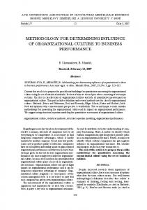
2. Methodology 2.1. Experiments In this research, 10 flat ring specimens of the Al-7075 aluminum alloy with geometry following the canonical aspect ratio 6:3:2 are submitted to ring compression tests at room temperature in a universal testing machine (model Hoytom 100kN), with application loads between 10 and 90 kN at a constant ram velocity of 25 mm/min. The lubrication on every test was performed by a graphite powder lubricant and the surface of the specimens was carefully cleaned before lubrication. This lubricant is expected to have a good behaviour against friction. Two different methodologies of load application have been used during the open die forging of rings: x Continuous forming methodology with lubrication only at the beginning of the forming process (Fig. 1a) x Incremental forming methodology with lubrication at the beginning of the forming process and intermediate lubrication after every incremental step (Fig. 1b)
(a)
(b)
Fig. 1. Forming methodologies: a) Continuous forging with only initial lubrication; b) Incremental forging with intermediate lubrication
309
J. Valero et al. / Procedia Engineering 132 (2015) 306 – 312
Measurements from height and inner diameter of every specimen were taken before and after the performance of the tests. Changes in height were performed using a millesimal micrometer (Fig. 2a) whereas a profile projector TESA VISIO (Fig. 2b) was used to determine changes in inner diameter. In order to perform a better measure of specimens with lower internal diameter reduction, specimens were cut along its cross section using a precision cutting machine, model Mecatome P100 (Fig. 2c).
(a)
(b)
(c)
Fig. 2. Dimensional measurements: a) Micrometer; b) Profile projector TESA VISIO; c) Precision cutting machine
2.2. Finite Element simulation Recent developments in computer technology have made significant contributions towards the application of numerical methods, especially the Finite Element Method (FEM), for solving complex plasticity problems which are difficult and time – consuming to solve by analytical methods. Concretely with ABAQUS we can solve a bi dimensional problem where axial symmetry exists, as in the case of the ring compression test considered in this paper. During the modeling stage, dies, workpiece, material and conditions are defined step by step. In order to obtain friction maps from FE simulation to compare them with calibration curves obtained by experimental ring compression tests, simulations for different values of the Coulomb friction coefficient (Table 1) were performed. Table 1. Coulomb friction coefficients used in the Finite Element model. Coulomb friction coefficient, μ 0.100
0.125
0.150
0.200
The friction factor maps are drawn in graphs where the percentage of reduction in high is shown in the x – axis and the percentage of decrease in internal diameter is presented in y – axis. Fig. 3 shows an example of the simulation realized for a reduction in height close to 50% and a Coulomb friction coefficient of 0.2.
Fig. 3. FEM simulation for rH = 49% and μ = 0.2
310
J. Valero et al. / Procedia Engineering 132 (2015) 306 – 312
When all measurements were realized, calibration curves were represented in a graph drawing percentage of reduction in height (x – axis) and reduction in internal diameter in y – axis. 3. Results and discussion Measurements obtained after the performance of ring compression tests in laboratory are presented in Table 2. Table 2. Results obtained by ring compression tests in laboratory and operating conditions. Methodology
Continuous
Incremental
Sample
H0
Di,0
v
F
Hf
Di,f
rH
rDi
(mm)
(mm)
(mm/min)
(kN)
(mm)
(mm)
(%)
(%)
1
3.389
5.186
25
90
1.537
2.426
55
53
2
3.359
5.254
25
75
1.723
2.734
49
48
3
3.094
5.320
25
60
1.776
3.378
43
37
4
3.430
5.167
25
45
2.224
3.972
35
23
5
3.344
5.040
25
30
3.281
5.023
2
0
6
3.234
5.243
25
90
1.492
2.577
54
51
7
3.111
5.192
25
75
1.578
2.916
49
44
8
3.353
5.158
25
60
1.865
3.572
44
31
9
3.209
5.082
25
45
2.115
4.075
34
20
10
3.344
5.040
25
30
3.281
5.023
2
0
Final geometries obtained with both methodologies are shown in Fig. 4 for the reduction stage corresponding to 75 kN of forging load. Sample on the left (Fig. 4a) shows the result using a continuous methodology whereas sample on the right (Fig. 4b) corresponds to incremental one.
(a)
(b)
Fig. 4. Final geometries of the rings tested in laboratory for a load of 75 kN: a) continuous methodology; b) incremental methodology
As explained in the previous section, tested samples have been cut along their diameters in order to precisely measure the final diameter after every reduction step. As an example, Fig. 5 shows the cut samples at the initial stage of 30 kN (Fig. 5a) and 75 kN-stage for the continuum (Fig. 5b) and incremental methodology (Fig. 5c).
J. Valero et al. / Procedia Engineering 132 (2015) 306 – 312
(a)
(b)
(c)
Fig. 5. Cut samples along the diameter corresponding to different forging loads: a) 30 kN-both methodologies; b) 75kN-continuous; c) 75kNincremental
Results from experiments and FE simulation are represented together in the same graph. Fig. 6 shows the friction calibration curves obtained in order to compare results. Finite element simulation shows curves with different friction coefficients in the range 0.125