Available online at www.sciencedirect.com
ScienceDirect Procedia CIRP 55 (2016) 146 – 151
5th CIRP Global Web Conference Research and Innovation for Future Production
Influence of Operating Variables during Flow Forming Process Ravi J Bhatta,*, Harit K Ravalb a
Research Scholar, Department of Mechanical Engineering, S V National Institute of Technology (SVNIT), Surat-395007, Gujarat, India b Professor, Department of Mechanical Engineering, S V National Institute of Technology (SVNIT), Surat-395007, Gujarat, India
* Corresponding author. Tel.: +91-9974411480; E-mail address:
[email protected]
Abstract Flow forming is gradually employed in production of high precision seamless components in the field of aerospace and defense. Rocket & missile casing, rocket motor case, cartridge case, rocket nose cones are few examples of flow forming process. The nature of process is non linear with complex deformation behavior. There are mainly two strategies used during the process viz. forward and backward/reverse. In forward method, the direction of roller feed and material deformation is same and in reverse method, the direction of roller feed and material deformation is opposite. Usually there are three force components encountered during the process i.e. axial, radial and circumferential. The understanding and knowledge of forces are crucial for tooling design for various geometrical and material conditions. The online force measurement during the process is quite difficult in commercial machines. Therefore, a simulation model is developed to estimate forces during the process. Taguchi L9 design has been used to develop the model because it is a well established design of experiment method to solve complex and time consuming problems. Three levels of three operating variables (rotational speed, axial feed and depth of forming) along with friction factor have been used during the study. The material utilized as Aluminum Alloy 6063 due to its light weight, excellent corrosion resistance, recyclable, cost effectiveness, ease of availability, durability etc. It has been observed that axial force is found to be highest followed by the radial and circumferential force. Also it has been discerned that axial feed and friction factor are the most prominent factors affecting axial and circumferential forces during the process. Further, radial force is influenced by friction factor only. The effect on von mises stress and equivalent plastic strain also studied and reported. © 2016 2017The TheAuthors. Authors. Published by Elsevier B.V.is an open access article under the CC BY-NC-ND license © Published by Elsevier B.V. This Peer-review under responsibility ofthe scientific committee of the 5th CIRP Global Web Conference Research and Innovation for Future (http://creativecommons.org/licenses/by-nc-nd/4.0/). Production.under responsibility of the scientific committee of the 5th CIRP Global Web Conference Research and Innovation for Future Production Peer-review Keywords: Operating Variables; Friction; Flow Forming; Forces; Von-mises Stress; Plastic Strain; Taguchi; ABAQUS
1. Introduction Flow forming is plastic deformation process which is specifically used to manufacture high precision seamless components for aerospace and defense industries. The application includes rocket motor case, cartridge case, missile casing etc. In this process, a deformable workpiece is placed over rigid mandrel and rollers are deforming it under contact area. Mainly two strategies adopted during process i.e. forward and backward/reverse. In forward method roller motion and deformation are in same direction (Fig. 1 (a)) and in reverse method; roller motion and deformation are in opposite direction (Fig. 1 (b)). It is important to have knowledge of behavior & pattern of deformation, forces
encountered, stresses generated in order to design tooling (rollers and mandrel) for different material and geometric condition. Several work reported on flow forming. Zoghi et al. [1] had investigated on hot tube necking of 42CrMo (steel) using finite element analysis. Those results were validated experimentally. Earlier, Zoghi et al. [2] had studied that non uniform contact during process leads to the non uniform deformation. Rasoli et al [3] did experimental study on flow forming using ultrasonic vibrations. The modal analysis is done by giving mandrel and roller ultrasonic vibrations. Based on the study, they found that inner surface quality of the tube can be improved by lower frequency of vibrations. Srinivasulu et al. [4] had concluded that annealing improves the mechanical properties of flow formed components. They had
2212-8271 © 2016 The Authors. Published by Elsevier B.V. This is an open access article under the CC BY-NC-ND license (http://creativecommons.org/licenses/by-nc-nd/4.0/). Peer-review under responsibility of the scientific committee of the 5th CIRP Global Web Conference Research and Innovation for Future Production doi:10.1016/j.procir.2016.08.025
Ravi J. Bhatt and Harit K. Raval / Procedia CIRP 55 (2016) 146 – 151
done experiments on single roller CNC machine for AA6082. Molladavoudi et al. [5] investigated that as the reduction of thickness increases; hardness, surface roughness and diametral growth increases while accuracy of geometry decreases. Nomenclature Fx Fy Fz f s d μ
Radial force Circumferential force Axial Force Axial Feed (mm/s) Rotational speed (RPM) Depth of forming (mm) Friction co-efficient
Abbreviation DOF SS MS
Degree of Freedom Sum Square Mean Square
simulation model is developed to estimate forces. Three operating parameters (rotational speed, axial feed, forming depth) and friction co-efficient are used during the study because these can be controlled manually by operator. The material is taken as AA6063 as it is widely used in aerospace and defense applications. 2. Analysis and Optimization Flow forming is affected by many factors like operating parameters, material properties and roller geometrical configurations as shown in Fig. 2. Operating variables are easily controllable while material properties and roller geometrical parameters are difficult to deal with. Because, material properties may varies from batch-to-batch and lot-tolot for same material. Furthermore, it is also difficult to vary roller configuration experimentally because several rollers consumes more material along with workpieces that increases material and inventory carrying cost. Therefore it is more convenient to use FE based tool to analyze such process by varying operating parameters to reduce raw material cost of workpiece and tooling.
Fig. 1(a) Configuration of Forward flow forming
Fig. 2 Different factors affecting forces, von mises and plastic strain
Fig. 1(b) Configuration of Backward/Reverse flow forming
Parsa et al. [6] developed correlation between feed with axial and angular velocities using FE simulations. Taguchi approach was employed by Davidson et al. [7] experimentally for AA6061 to determine significant factor which affecting the flow forming process. However, online measurements of forces are still difficult in commercial machines. Also, trial and error method normally adopted to work out optimal combination of parameters for different conditions. That increases lead time, indirect cost and waste. Hence, a
In the present study, operating parameters are concentrated as those can be controlled for uniform quality of products. The operating parameters (rotational speed, axial feed and forming depth) selection is done based on the literature review and some preliminary experimentation. Moreover, friction factor is also considered to investigate its effect on forces. In practice, friction can be regulated by the different lubricating conditions. The backward/reverse strategy has been adopted because it doesn’t require any special fixture to grip workpiece during and after operation. Normally three forces are encountered during the process i.e. axial, radial and circumferential. Figure 3 (a) and 3 (b) shows the initial model with meshed blank and forces acting during process respectively. Here, AA6063 has been chosen as work material because it serves several advantages like light weight, excellent corrosion resistance, recyclable, high ductility, and various applications in aerospace and defense sectors. The mechanical properties of AA 6063 are [8]: density (ρ) = 2700 kg/m3, YS (yield strength) = 48.3 MPa, elastic modulas = 68.9 GPa, poisson’s ratio = 0.33, US (ultimate strength) = 89.6
147
Ravi J. Bhatt and Harit K. Raval / Procedia CIRP 55 (2016) 146 – 151
Fig. 3(a) 3D model with meshed blank
166
30
164
25
162
Von Mises (Mpa)
20
Computational Time (Hr.)
15
160 158
10
156
5
154 152
Computational time (Hr)
of three operating variables (rotational speed, axial feed forming depth) and three levels of friction co-efficient. The parameters with their values are given in Table 1 and simulation layout is provided in Table 2. The optimization of best combinations has been carried out using ANOVA (Analysis of Variance). Minitab has been used to generate and analyze the L9 design.
Von mises stress (MPa)
Mpa and the configuration details are [8]: diameter of blank/workpiece = 35 mm, thickness of wall = 2.5 mm, Initial length of workpiece = 50 mm, diameter of roller = 54 mm, roller attack angle = 25°, relief angle of roller = 5° and reduction = 40%.
0 0 0.5 1 1.5 2 2.5 3 3.5 4 4.5 5
5.5
Mesh size (mm)
Fig. 3(b) Forces acting during process
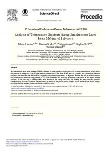
The initial and boundary conditions are applied based on the rotary and linear motions. 1) The workpiece is fixed on the mandrel and free to move with the mandrel rotation. 2) Roller and mandrel rotation are opposite to each other. 3) Workpiece is fixed at one end (normally considered as chuck side) and free to deform on opposite side (normally considered as tail stock side). Also, roller and mandrel are taken as analytical rigid bodies (do not require meshing) which helps to reduce computational time and memory storage. The optimum mesh size (using mesh sensitivity analysis) is decided by taking several mesh size from 0.5 to 5 mm (in interval of 0.5 mm) as shown in Fig 4. It can be seen that finer mesh (0.5 mm) gives better results compared to courser mesh. Also, the CPU time is slightly higher in fine mesh compared to course mesh. Further, adaptive meshing was used in the forming area considering ALE (Arbitrary Lagrangian Eluerian) method to prevent severe mesh distortion during analysis. Dry friction has been considered between mandrel and workpiece and friction is varied between roller and workpiece as discussed earlier. The simulation procedure has been benchmarked (Fig. 5(a) and 5(b)) with [8] in which forward strategy had adopted. It can be seen that the trend of equivalent plastic strain vs distance from surface and kinetic energy vs time are very much identical with marginal difference. The optimization is carried out using Taguchi et al. [9] method as it is well developed design of experiment method to analyze costly and complex experiments. In present case, Taguchi L9 design has been used which includes three levels
Equivalent Plastic Strain
Fig. 4 Mesh sensitivity analysis
4 3.5 3 2.5 2 1.5 1 0.5 0
Literature [8] (Forward Strategy) Present Study (Backward Strategy)
0
0.5 1 Distance from Surface (mm)
1.5
Fig. 5 (a) Benchmarked results of equivalent plastic strain 600 Kinetic Energy (J)
148
Literature [8] (Forward Strategy)
500
Present Study (Backward Strategy)
400 300 200 100 0 0
2
4
Time (s)
6
8
10
Fig. 5 (b) Benchmarked results of kinetic energy Table 1 Parameters and their values. Parameters
Level 1
Level 2
Level 3
Forming Depth (mm) (d)
0.2
0.4
0.6
Rotational Speed (RPM) (s)
30
60
90
Axial Feed (mm/rev) (f)
0.05
0.10
0.15
Friction Co-Efficient (μ)
0.15
0.20
0.25
Taguchi had illustrated three types of quality measures i.e. smaller the better, nominal the better and larger the better. In present study forces should be minimum along with von mises stress therefore smaller the better quality characteristics has
149
Ravi J. Bhatt and Harit K. Raval / Procedia CIRP 55 (2016) 146 – 151
been utilized for analysis of forces and von mises stress. On the other hand, plastic strain should be larger. Hence, larger the better quality criteria has been employed for plastic strain during the analysis.
Parameters
Rotational Speed (RPM)
Ax ial feed (mm/rev)
Friction Co-ef ficient
-48 -49
Mean of SN ratios
Table 2 Simulation layout (L9 array) Simulation No.
Forming Depth (mm)
-47
-50 -51 -52 -53
Forming Depth (mm)
Rotational Speed (RPM)
Axial feed (mm/rev)
Friction Coefficient
1
0.2
30
0.05
0.15
2
0.2
60
0.1
0.2
3
0.2
90
0.15
0.25
4
0.4
30
0.1
0.25
5
0.4
60
0.15
0.15
3000
6
0.4
90
0.05
0.2
2500
7
0.6
30
0.15
0.2
8
0.6
60
0.05
0.25
9
0.6
90
0.1
0.15
-54 -55 -56 0.2
0.4
0.6
30
60
90
0.05
0.10
0.15
0.15
0.20
0.25
Forces (N)
Fig. 8 Graph of S/N ratio of circumferential force
Axial
Radial
Circumferential
2000 1500 1000 500 0
3. Results and Discussion
0
Taguchi et al. [9] had stated that better performance is the function of higher S/N (signal to noise) ratio. The main effect plots (graph of S/N ratio) for axial, radial and circumferential forces are given in Fig. 6, 7 and 8 respectively. Also, a sample plot of forces (simulation 3) is given in Fig. 9. Forming Depth (mm)
Rotational Speed (RPM)
Axial feed (mm/rev)
Friction Co-efficient
-56 -57
Mean of SN ratios
-58 -59 -60 -61 -62 -63 -64 -65 0.2
0.4
0.6
30
60
90
0.05
0.10
0.15
0.15
0.20
0.25
Fig. 6 Graph of S/N ratio of axial force Forming Depth (mm)
Rotational Speed (RPM)
Axial feed (mm/rev)
Friction Co-efficient
Mean of SN ratios
-50
-52
-54
-56
-58 0.2
0.4
0.6
30
60
90
0.05
0.10
0.15
0.15
Fig. 7 Graph of S/N ratio of radial force
0.20
0.25
5
Time (s) 10
15
20
Fig. 9 Forces during simulation (no. 3)
It can be seen from Fig. 6 that the optimal performance for the axial force can be achieved at 0.2 mm depth of forming (level 1), 60 rpm speed (level 2), 0.05 mm/rev feed (level 1) and 0.15 friction factor (level 1). Further, 0.2 mm depth of forming (level 1), 60 rpm speed (level 2), 0.05 mm/s feed (level 1) and 0.20 friction factor (level 2) having significant effect on radial force (Fig. 7). The optimal performance of the circumferential force can be obtained at 0.2 mm depth of forming (level 1), 60 rpm speed (level 2), 0.05 mm/s speed (level 1) and 0.15 friction factor (level 1) as shown in Fig. 8. Such way, it has been observed that forming depth, axial feed and friction co-efficient having significant effect (statistically) on forces. Further, it can be observed from Fig. 9 that the axial force is found to be highest followed by radial and circumferential. Similar results observed for all the simulations. It was noticed that forces of simulation no. 3 (i.e. 0.2 mm depth, 90 rpm speed, 0.15 mm/s feed and 0.25 friction factor) were found to be highest. The values of forces are found as 2500 N axial, 1800 N radial and 1000 N circumferential approximately. The shear and compressive forces acting on the contact face of the roller during deformation. Hence axial force is found to be highest. The radial force is found to be second due to depth of forming provided by the roller. The instantaneous contact during the process between roller and workpiece due to rotation of roller leads the smallest value of circumferential force. Moreover, ANOVA (analysis of variance) has been carried out to identify most significant parameter affecting the process. The P-value represents the statistical importance of individual parameters. It was stated by Taguchi et al. [9] that the p-value should be less than 0.05 for the 95% confidence level. Table 3, 4 and 5 represents the ANOVA of the axial, radial and circumferential force respectively. It can be
150
Ravi J. Bhatt and Harit K. Raval / Procedia CIRP 55 (2016) 146 – 151
observed that axial feed and friction co-efficient are the most significant parameters for axial and circumferential forces for 95% confidence level (Table 3 and Table 5). Whereas, only friction co-efficient is found to be significant for radial force (Table 4). In present case pooled ANOVA has been carried out to find out p-value. (Note: The % notation indicates the percentage contribution of the factors for all the ANOVA tables.) Table 3 ANOVA of axial force Factor
DOF
SS
MS
F
P
%
Forming Depth (mm)
2
432289
216144
-
-
9.60
2
651489
325744
1.5070
0.39
14.46
2
1986756
993378
4.5959
0.017
44.12
2
1432289
716144
3.3132
0.023
31.80
Rotational Speed (RPM) Axial feed (mm/rev) Friction Coefficient Error
0
-
-
-
-
-
Total
8
4502822
-
-
-
-
Pooled Error
2
432289
216144
-
-
-
(a). It shows that optimal performance of von mises stress can be obtained at 0.2 mm (level 1) depth of forming, 60 rpm (level 2) speed, 0.15 mm/s (level 3) and 0.20 friction (level 2). It is because of higher forces encountered at higher feed therefore higher stresses generated. Further, as can be seen from Fig. 11 (b) that optimal performance for the equivalent plastic strain can be obtained at 0.6 mm (level 3) depth of forming, 30 rpm (level 1) speed, 0.10 mm/s (level 2) and 0.25 friction factor (level 3). It is also due to the depth of forming, as the forming depth increases, the plastic strain increases.
Fig. 10 (a) Von Mises stress (simulation no. 1)
Table 4 ANOVA of radial force Factors
DOF
SS
MS
F
P
%
Forming Depth (mm)
2
62017
31008
-
-
7.55
2
149450
74725
2.4098
0.29
18.19
2
293217
146608
4.7280
0.17
35.69
2
316717
158358
5.1070
0.016
38.55
Error
0
-
-
-
-
-
Total
8
821400
-
-
-
-
Pooled Error
2
62017
31008
-
-
-
Table 5 ANOVA of circumferential force Factors Forming Depth (mm) Rotational Speed (RPM) Axial feed (mm/rev) Friction Coefficient
Fig. 10 (b) Equivalent Plastic Strain (simulation no. 1) Forming Depth (mm)
Rotational Speed (RPM)
Ax ial feed (mm/rev)
Friction Co-eff icient
-44.2
-44.4
Mean of SN ratios
Rotational Speed (RPM) Axial feed (mm/rev) Friction Coefficient
-44.6
-44.8
-45.0
-45.2
DOF
SS
MS
F
P
%
2
80506
40253
1.0671
0.48
15.13
2
75439
37719
-
-
14.18
2
207206
103603
2.7467
0.026
38.95
2
168739
84369
2.2367
0.030
31.72
4
-45.4
-45.6 0.2
0.6
30
60
90
0.05
0.10
0.15
0.15
0.20
0.25
Fig. 11 (a) Graph of S/N ratio of von mises stress Forming Depth (mm)
0
-
-
-
-
-
3
Total
8
531889
-
-
-
-
2
Pooled Error
2
75439
37719
-
-
-
Mean of SN ratios
Error
Moreover, von mises stress and equivalent plastic strain was also considered during the study. Fig. 10 (a) and 10 (b) represents the sample of von mises stress and equivalent plastic strain (simulation no. 1) respectively. It is observed that the von mises stress found to be highest as 199.5 MPa and plastic strain as 1.92 for third simulation. The effect of operating parameters on von mises stress is given in Fig. 11
0.4
Rotational Speed (RPM)
Ax ial f eed (mm/rev)
Friction Co-efficient
1 0 -1 -2 -3 -4 0.2
0.4
0.6
30
60
90
0.05
0.10
0.15
0.15
0.20
Fig. 11 (b) Graph of S/N ratio of equivalent plastic strain
0.25
Ravi J. Bhatt and Harit K. Raval / Procedia CIRP 55 (2016) 146 – 151
Further, Table 6 and 7 shows the ANOVA of the von mises stress and equivalent plastic strain respectively. It can be seen that the depth of forming is more prominent factor affecting von mises stress and equivalent plastic strain during the process based the 95% confidence level. Table 6 ANOVA of von mises stress Factors
DOF
SS
MS
F
P
%
2
997.83
498.91
33.8244
0.02
80.14
2
73.42
36.71
2.4888
0.28
5.89
2
29.51
14.75
-
-
2.37
2
144.24
72.12
4.8894
0.16
11.58
Forming Depth (mm) Rotational Speed (RPM) Axial feed (mm/rev) Friction Coefficient Error
0
-
-
-
-
-
Total
8
1245
-
-
-
-
Pooled Error
2
29.51
14.75
-
-
-
DOF
SS
MS
F
P
%
2
1.0533
0.5266
9.3045
0.017
68.04
2
0.1132
0.0566
-
-
7.31
2
0.1552
0.0776
1.3713
0.42
10.02
2
0.2262
0.1131
1.9982
0.33
14.61
Error
0
-
-
-
-
-
Total
8
1.5479
-
-
-
-
Pooled Error
2
0.1132
0.0566
-
-
-
Forming Depth (mm) Rotational Speed (RPM) Axial feed (mm/rev) Friction Coefficient
Based on the present study, following broad conclusions are derived. Axial feed and friction co-efficient are the most prominent factors affecting axial and circumferential forces. It is noted that 0.2 mm forming depth and 0.15 friction factor gives better results. Further, friction factor has significant effect on radial force. Axial force is found to be highest during all simulation runs followed by the radial & circumferential force. Depth of forming having significant effect on the von mises stress and plastic strain During Simulation no. 3 (i.e. 0.2 mm depth, 90 rpm speed, 0.15 mm/s feed and 0.25 friction coefficient) forces, von mises, and plastic strain are found to be highest. Acknowledgements
Table 7 ANOVA of equivalent plastic strain Factors
4. Conclusions
It has been observed that depth of forming having significant effect on von mises stress and plastic strain. The reason is, as the forming depth increases; more material comes into contact zone for deformation hence more forces are required for deformation thus increase in the von mises stress. Similarly higher amount of material deformation causes higher plastic strain. But necessary tradeoff is required between forces and von mises stress to achieve desired deformation. Because higher depth may rise the material bulging that resists further deformation. Also higher amount of speed and feed could increase the intensity of forces which leads to defects in formed product and it could also damage the surface of the rollers. In present work, Taguchi analysis as well as ANOVA is carried out to investigate effect of operating parameters and friction factor on forces, von mises stress and equivalent plastic strain. It can be noticed that the axial feed and friction factor are affecting the axial and circumferential forces significantly compared to forming depth and rotational speed. Radial force is influenced by the friction factor only. Besides, forming depth is having more significant effect on von mises stress and equivalent plastic strain.
The first author is thankful to the director and other technical staff of Mechvac Fabricators, India for providing in depth understanding and knowledge about flow forming process. References [1] Zoghi H, Arezoodar AF. Finite element study of stress and strain state during hot tube necking process. Proce. Insti. Mech. Eng. Part B: J Engi. Manuf. 2013; 227(4): p. 551-564 [2] Zoghi H, Arezoodar AF, Sayeaftabi M. Effect of feed and roller contact start point on strain and residual stress distribution in dome forming of steel tube by spinning at an elevated temperature. Proce. Insti. Mech. Eng. Part B: J Engi. Manuf. 2012; 226(11): p. 1880-1890 [3] Rasoli MA, Abdullah A, Farzin M, Tehrani AF, Taherizadeh A. Influence of ultrasonic vibrations on tube spinning process. J Mater. Proce. Technol. 2012; 212(6): p. 1443-1452 [4] Srinivasulu M, Komaraiah M, Krishna Prasad Rao CSK. Experimental studies on the characteristics of AA6082 flow formed tubes. J Mech. Eng. Res. 2012; 4: p. 192-198 [5] Molladavoudi HR, Djavanroodi F. Experimental study of thickness reduction effects on mechanical properties and spinning accuracy of aluminum 7075-O, during flow forming. Int. J Adv. Manuf.Technol. 2011; 52(9-12): p. 949-957 [6] Parsa MH, Pazooki AMA, Nili AM. Flow forming and flow formability simulation. Int. J Adv. Manuf.Technol. 2009; 42(5-6): p. 463-473 [7] Davidson JM, Balasubramanian K, Tagore GRN. Experimental investigation on flow-forming of AA6061 alloy-A Taguchi approach. J Mater. Proce. Technol. 2008; 200 (1-3): p. 283-287 [8] Mohebbi MS, Akbarzadeh A. Experimental study and FEM analysis of redundant strains in flow forming of tubes. J Mater. Proce. Technol. 2010; 210 (2): p. 389-395 [9] Taguchi G, Chowdhury s, Wu Y. Taguchi’s Quality Engineering Handbook, Second Ed. John Wiley and Sons, Inc.; 2005 [10] Abaqus user guide, 2013
151