Nov 16, 2011 - We present the first experimental studies of the initial source of electron beam microbunching instability in a free .... stage bunch compressor if the longitudinal profile of ... IR to extreme UV wavelengths. ..... D 39, 2780 (1989).
PHYSICAL REVIEW SPECIAL TOPICS - ACCELERATORS AND BEAMS 14, 110701 (2011)
Initial source of microbunching instability studies in a free electron laser injector S. Seletskiy, Y. Hidaka, J. B. Murphy, B. Podobedov, H. Qian, Y. Shen, X. J. Wang, and X. Yang National Synchrotron Light Source, Brookhaven National Laboratory, Upton, New York 11973, USA (Received 15 March 2011; published 16 November 2011) We present the first experimental studies of the initial source of electron beam microbunching instability in a free electron laser (FEL) injector. By utilizing for the studies a transform-limited laser pulse at the photocathode, we eliminated laser-induced microbunching at the National Synchrotron Light Source Source Development Laboratory (SDL). The detailed measurements of the resulting electron beam led us to conclude that, at SDL, microbunching arising from shot noise is not amplified to any significant level, thereby allowing us to set an upper limit on the initial modulation depth of microbunching arising from shot noise. Our analysis demonstrated that the only significant source of microbunching instability under normal operational conditions at SDL is the longitudinal modulation of the photocathode laser pulse. Our work shows that assuring a longitudinally smoothed photocathode laser pulse allows mitigating microbunching instability at a typical FEL injector with a moderate microbunching gain. DOI: 10.1103/PhysRevSTAB.14.110701
PACS numbers: 29.27.Bd, 29.27.Fh, 41.60.Cr
I. INTRODUCTION Beams of subpicosecond length typically required for free electron lasers (FELs) are obtained from longer beams compressed in bunch compressors at relativistic energies [1,2]. The bunch compressor manipulates longitudinal phase space of the beam with correlated energy spread by introducing the dependence of the particles’ longitudinal coordinate within the beam on their relative energy. A linear accelerator utilizing bunch compressors can amplify, with a large gain factor, the initial small modulation in either electron beam energy or its longitudinal density [3–6]. This process can degrade the FEL performance [7] by increasing the fragmentation of longitudinal phase space (i.e., microbunching) and is known as microbunching instability. Microbunching instability usually occurs due to the beam wakefields converting small initial density modulations into energy modulations that, in turn, are transformed into density modulations of larger amplitude in the dispersive region. The repetition of this process at each stage of bunch compression entails the multistep enhancement of microbunching. It is assumed that the initial modulation of the beam either is induced by the temporal modulation of photocathode laser [8] or starts from the shot noise [9,10]. The depth of the initial beam modulation that may be of concern for FEL performance typically is in the range of 0.01%–1% [9,11,12]. The range of wavelengths where the instability gain is highest is from several microns to several hundred microns [13,14]. Another adverse effect of microbunching is the coherent optical
Published by the American Physical Society under the terms of the Creative Commons Attribution 3.0 License. Further distribution of this work must maintain attribution to the author(s) and the published article’s title, journal citation, and DOI.
1098-4402=11=14(11)=110701(8)
transition radiation (COTR) ruining the beam profile diagnostics at OTR stations downstream of beam compression. Such effects were observed, for instance, at SLAC Linac Coherent Light Source (LCLS) [15] and ANL Advanced Photon Source [16,17]. The visible COTR can be attributed to the microbunching related to the longitudinal space charge (LSC) impedance and is consistent with the 3D LSC modeling [18]. COTR was observed at SDL [19] at much stronger than normal bunch compression. It is currently believed that SDL COTR is not directly related to microbunching. Microbunching instability can come from LSC wakefield. Coherent synchrotron radiation (CSR) [4,20] and linac wakefields [14] also contribute to the development of the instability. In the previous SDL studies [21–24], the experimental characterization of microbunching provided significant insights into the mechanism of the instability. The spiky energy spectrum of compressed electron beam observed in SDL operations was explained by applying the LSC dominated model to a beam with small initial density modulations. It was shown that these modulations can generate high-frequency energy modulations of amplitude exceeding, by a large factor, the intrinsic electron beam energy spread. It was speculated that the photocathode laser could be the source of initial density modulations. As a possible remedy against microbunching instability, a so-called laser heater was proposed [25] and subsequently built and commissioned at LCLS [11]. Indeed, it successfully mitigated [26–28] microbunching instability and enhanced the FEL performance. Though the microbunching instability is controlled reasonably well for the LCLS SASE FEL, there remains a certain level of microbunching in the beam, that generates COTR negatively affecting the beam diagnostics utilized for measuring the beam profile [27]. It is also expected that microbunching
110701-1
Published by the American Physical Society
S. SELETSKIY et al.
Phys. Rev. ST Accel. Beams 14, 110701 (2011)
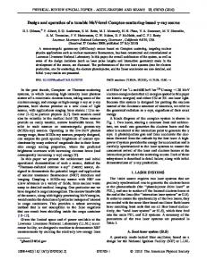
instability may become more severe in future machines with higher brightness, and in seeded FELs that demand much better control of the longitudinal phase space than do SASE FELs. Thus, it is believed that further studies of this instability will greatly reduce the risks for such machines; accordingly, such studies remain a very active research area. For example, a recent theoretical development in the research of microbunching instability suggests a design for accelerator lattices that naturally suppress microbunching [12]. What is missing is the solid experimental evidence characterizing the source of initial microbunching. Hence, we explored the source of initial microbunching in controlled studies by separating the microbunching arising due to shot noise from laser-induced microbunching. Preliminary results of this work were described in [29]. Our approach was to use an ultrashort transform-limited photocathode laser pulse. While using long and smooth laser pulse would simplify analysis of experimental data, the choice of transform-limited pulse was determined by its immediate availability at SDL. The typical spectrum of this pulse is presented in Fig. 1. Both spectral and cross-correlation measurements indicate that such a laser pulse is clean, pedestal free, and contains no satellite pulses. This excludes the possibility of laser-induced modulation of the longitudinal beam density. Observing the evolution of beam longitudinal phase space through the stages of acceleration and comparing high resolution zero-phase measurements to the numerical simulations allowed us to conclude that, in the absence of laser-induced modulations, there is no observable microbunching at the SDL. Furthermore, this let us set the upper limit on the initial modulation depth of microbunching arising from the shot noise. Our studies demonstrate that microbunching instability can be controlled in a typical FEL injector with a single stage bunch compressor if the longitudinal profile of
FIG. 1. Spectrum of the transform-limited 100 fs-long laser pulse used in the experiment.
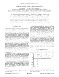
photocathode laser pulse is smooth. This result may have significant implications for future designs of FEL injectors. The paper is organized as follows. In Sec. II we give the background for the subsequent study. In Sec. III we describe the experimental exploration of possible microbunching in the absence of laser-induced modulation of the beam, and draw a conclusion on the sources of microbunching instability. The results are discussed in Sec. IV. II. STUDY BACKGROUND A. SDL facility In the SDL [30], the electron beam generated in the photocathode rf gun is first accelerated to about 70 MeV, utilizing two linac tanks of the SLAC type. It is then compressed in the bunch compressor (BC) consisting of the linac section, which introduces a correlated energy spread (chirp), and a four-bend chicane, which produces relevant momentum compaction. Following the bunch compressor are three more 3 m long SLAC-type linac sections able to accelerate the electron beam up to 300 MeV. After the acceleration, the beam passes through a 10 m long undulator to produce coherent radiation from IR to extreme UV wavelengths. The SDL beam line is equipped with a spectrometer magnet located downstream of the bunch compressor, followed by a beam profile monitor (BPM). Figure 2 schematically shows the SDL layout. The photocathode rf gun is illuminated by a frequency tripled Ti:sapphire laser at 266 nm. The SDL Ti:Sa laser system consists of a 100 fs rf synchronized oscillator and a chirped pulse amplifier. During SDL routine operations, a 10 ps FWHM long laser with a residual chirp is used. Typically, the resulting electron beam at the gun exit has charge in the range of 0.1–0.5 nC and the length of 5 ps FWHM (electron beam undergoes factor of 2 compression in the gun). The electron beam energy spectrometer located downstream of the fifth linac tank can be utilized to obtain a beam temporal profile as well as its energy spectrum. For the former, one can use the rf zero phasing method [31]. The electron beam is energy chirped by one of the linac sections set to the nonaccelerating (zero) phase, and then it is dispersed by a dipole magnet, so that the different time slices of the beam are projected on the scintillating screen at different positions. The rms time resolution is given by [31]
FIG. 2. The SDL layout. The gun and the first two linac tanks are powered by a single klystron.
110701-2
INITIAL SOURCE OF MICROBUNCHING INSTABILITY . . . �t ¼
E�x ¼ 7 fs; �Erf krf c
(1)
where E ¼ 70 MeV is the beam energy, �x ¼ 150 �m is the minimized rms horizontal beam size on the scintillator with the zero phasing section off determined by the uncorrelated energy spread and the lattice beta function, � ¼ 1:1 m is the dispersion at the location of the BPM, Erf ¼ 60 MeV is the maximum voltage in the zero phasing linac section, krf ¼ 59:9 m�1 is the rf wave number, and c is the speed of light. B. Microbunching gain at SDL The beam density modulation at the beginning of a FEL injector can be characterized by a bunching factor [4] bðkÞ ¼
1 Z IðzÞe�ikz dz; Nec
where N is the number of electrons in the beam, e is the electron charge, IðzÞ is the beam current, and z is the coordinate along the beam. The wakefield upstream of the bunch compressor converts density modulation into energy modulation. The energy modulation of amplitude �� prior to BC is converted into additional density modulation characterized by bf ðkf Þ due to nonzero dispersion in the bunch compressor. The gain factor defined as GðkÞ � bf ðkÞ bðkÞ
is [5] � � � � � � � �� � 1 � � 2 � ðCkR � =�Þ exp � ; G¼� CkR � � 56 56 � � � � �bðkÞ � 2
(2)
where C ¼ 1=ð1 þ hR56 Þ is the compression ratio, h is the beam chirp, R56 is the compaction factor, � ¼ E=mc2 , m is the mass of the electron, and �� ¼ �E =mc2 is the rms energy spread. Equation (2) is derived in approximation of small modulation wavelength, k�z � 1. The wakes upstream of the bunch compressor are due to LSC and the vacuum chamber geometry. The free-space expression for LSC impedance per unit length can be used for �=ðkrvc Þ � 1 (rvc is the radius of the vacuum chamber) [32]: � � �� iZ0 krb kr K1 b ; (3) ZLSC ðkÞ ¼ 1� 2 � � �krb where Z0 ¼ 377 � is the free-space impedance, rb is the beam radius for a uniform transverse distribution, and K1 is the modified Bessel function. The evolution of the bunching spectrum along the injector can be represented by the integral equation [20]: bðk; sÞ ¼ bðk; 0Þ þ i4�k
I Zs ~ Zðk; zÞ bðk; zÞdz: R56 ðz ! sÞ IA 0 Z0 (4)
Phys. Rev. ST Accel. Beams 14, 110701 (2011)
Here IA ¼ 17 kA is Alfven current and R~56 ðz ! sÞ is the ratio of the path length change at s due to a small change in � at z given by Z s dx R~ 56 ðz ! sÞ ¼ : 3 z �ðxÞ The change in the energy modulation along the linac is 4�I Z s Zðk; zÞbðk; zÞdz: (5) ��ðk; sÞ ¼ � Z0 IA 0 In a drift, where � is constant, R~56 ðz ! sÞ ¼ ðs � zÞ=�3 , which leads to the solution representing space charge oscillation with the frequency sffiffiffiffiffiffiffiffiffiffiffiffiffiffiffiffiffiffiffiffiffiffiffiffiffi 4�I0 jZðkÞjk �¼c : �3 IA Z0 At a sufficiently high energy, the period of space charge oscillations becomes so large that the current modulation is essentially frozen and the energy modulation induced through wakefields can be calculated as 4�Ibðk; 0Þ Z s ��ðk; sÞ ¼ � Zðk; zÞdz: (6) IA Z0 0 Applying this model to the SDL injector, we compute energy modulation driven by LSC by numerically solving (4) and (5) upstream the exit of the first accelerating section and we use (6) downstream of it down to the chicane. Substituting obtained net amplitude of energy modulation in (2), we find that the LSC-driven microbunching instability is completely suppressed for initial wavelengths smaller than 20 �m, at larger wavelengths the gain is quickly growing reaching its maximum value of GLSC � 120 at approximately 90 �m. The microbunching suppression at high frequencies is determined by the uncorrelated energy spread causing the smearing of microbunching across the chicane. Figure 3 shows the
FIG. 3. Microbunching gain at SDL through LSC, CSR, and linac wakes. The LSC-driven gain (left axis) is shown by the solid blue line. Gains driven by CSR and linac wakes (right axis) are shown by the dashed purple and the dotted green lines, respectively. The calculations are performed for 40 pC, 0.8 ps FWHM long beam with C ¼ 4 and R56 ¼ 6 cm.
110701-3
S. SELETSKIY et al.
Phys. Rev. ST Accel. Beams 14, 110701 (2011)
microbunching gain calculated for beam parameters discussed in the next section. For linac wakes in the high-frequency approximation, the impedance per unit length is given by [33] � � � � iZ0 �p � 1=2 �1 Zlinac ðkÞ � 1 þ ð1 þ iÞ a kg �ka2 and for SLAC structure the iris radius a ¼ 1:16 cm, the gap length g ¼ 2:92 cm, and the average period p ¼ 3:50 cm. The geometric factor � � 0:5 for g � p. This steady-state regime expression overestimates the wake, which, however, does not change our conclusion, since the linac wake turns out to be small. As it is shown in Fig. 3, the microbunching gain from linac wakes calculated from (6) and (2) is absent; this is because the accelerator upstream of the chicane consists of just two 3 m long linac sections. Finally, the mechanism of CSR microbunching instability is similar to the mechanism of instability driven by LSC and linac wakes. Initial density modulation induces energy modulation through CSR impedance and is subsequently turned into additional density modulation through respective R56 , therefore giving a rise to CSR-driven microbunching instability. The evolution of beam bunching in the chicane in the presence of CSR wake is [4] Zs bðk; sÞ ¼ bðk; 0Þ þ Kðz; sÞbðk; zÞdz; (7) 0
where the kernel of the integral equation is I0 CðzÞZCSR ðkCðsÞ; zÞ �IA � � 2 � 2 2 k U ðs; zÞð�� =�Þ2 k �� exp � � exp � 2 2 � �2 � � k2 � 2 W ðs; zÞ : � Vðs; zÞ � Wðs; zÞ � � 2�
Kðz; sÞ ¼ ikCðsÞR56 ðz ! sÞ
can expect to see microbunching amplification at wavelengths � 20 �m. The substructures of these sizes can be easily detected by SDL longitudinal diagnostics as its resolution, given by Eq. (1), is more than adequate. At the given gain of microbunching instability we expect to be able to detect the amplification of initial modulations of as low amplitude as � 0:03%, since the final modulation at the level of a few percent is easily observable. III. EXPERIMENTAL RESULTS AND INTERPRETATION In the set of experiments described in this paper, we used a Gaussian 100 fs (FWHM) laser. Using a short laser eliminates laser-induced microbunching instability, as discussed above. The experimental beam charges were in the range of 10–100 pC. The observed behavior for all charges was very similar. In addition, calculations demonstrated that there is no qualitative change in the dynamics of possible microbunching instability for beam of 100 pC charge compared to one of 40 pC charge, for instance. The increase in peak current is moderate since the resulting length of the beam increases with beam charge; the LSC gain still totally dominates the CSR and linac wake gains. The cutoff wavelength for microbunching amplification remains around 20 �m, and the LSC gain rises only by a factor of 1.1 at its maximum. On the other hand, beams of lower charge provide clearer pictures in spectrometer wherein the features of microbunching are better pronounced. From here, we consider the dynamics of 40 pC beam. It is about 0.8 ps FWHM at the exit of the gun, as both measurements and simulations show. The spectrum of the uncompressed beam shows no signs of longitudinal fragmentation. In contrast, the compressed beam spectrum exhibits distinct spikes (Fig. 4). The first breakups in longitudinal phase space are observed at C � 2:5, and the modulation becomes most pronounced at C ¼ 4.
Here � is the beam emittance, � and � are Twiss functions at the chicane entrance, CðsÞ ¼ 1=½1 þ hR56 ðsÞ�, Z0 k1=3 ZCSR ðk; sÞ ¼ ð1:63 þ 0:94iÞ 4� ðsÞ 2=3 is CSR impedance, and Uðs; zÞ ¼ CðsÞR56 ðsÞ � CðzÞR56 ðzÞ Vðs; zÞ ¼ CðsÞR51 ðsÞ � CðzÞR51 ðzÞ Wðs; zÞ ¼ CðsÞR52 ðsÞ � CðzÞR52 ðzÞ: R51 and R52 are elements of the transfer matrix. Equation (7) can be iteratively solved [4] for a fourdipole chicane providing an approximate analytical solution for CSR gain. For the SDL parameters the calculated CSR gain (Fig. 3) is rather small for the modulation wavelengths of interest, which is in agreement with [21,22]. As one can see from the above consideration, LSC dominates microbunching instability at SDL linac. One
FIG. 4. Spectra of uncompressed (left plot) and compressed (right plot) beams.
110701-4
INITIAL SOURCE OF MICROBUNCHING INSTABILITY . . . To evaluate the period of modulation and the characteristic width of the spikes, we removed the chirp remaining after compression by the third linac section, and then spread the beam longitudinally using the fourth section for zero phasing; Fig. 5 shows the respective pictures at the spectrometer scintillating screen. If we interpret the substructures therein as density modulations, their width can be estimated as arcsinð�E=Erf Þ=krf � 15 �m where the characteristic size of observed substructures is �E � 30 keV and Erf in tank 4 was set to 32 MeV. Similarly, the period of this modulation is about 60 �m. The observations described above might be interpreted as the spontaneous microbunching of a beam with an initial modulation of � 0:5%–1%, amplified through LSC-driven instability. Indeed, the size of substructures in the compressed beam would correspond to the initial small spontaneous modulation at � 60 �m and the period of observed spectrum fragmentation corresponds to an initial modulation at 240 �m. Since the gain at 60 �m is about 100, and at 240 �m is close to 60, we would expect to observe strong modulation of compressed beam with spike width of 15 �m and modulation period of 60 �m. However, careful analysis of the beam dynamics proves that this conclusion is incorrect. Below we show that the observed dramatic modulation of the longitudinal phase space is not a result of microbunching but rather is ‘‘macrobunching’’—the net modulation of the beam with initially smooth longitudinal profile by different self-fields acting on the beam as a whole. At low energies, especially in the gun and drift before the first acceleration tank, space charge effects dominate the evolution of the beam longitudinal phase space. Taking into account the shielding effect of the vacuum chamber, the LSC field is [34] Ez ¼
� � �� @IðzÞ Z0 rvc 1 þ 2 ln : 2 @z 4�� rb
FIG. 5. The left plot shows the beam observed at the spectrometer with the chirp removed by tank 3. The right plot shows zero phasing measurement of such beam performed with tank 4.
Phys. Rev. ST Accel. Beams 14, 110701 (2011)
This field can modulate the beam energy significantly. Indeed, PARMELA [35] simulations show that from photocathode to the entrance of second linac section the beam acquires substantial energy modulation at the wavelength comparable to the bunch length. Reconstructing the longitudinal phase space of uncompressed beam [36] confirms these simulated results, as demonstrated in Fig. 6. Considered macromodulation in energy becomes density modulation at compressed wave number kmacro � C�=ð2�z Þ as the beam passes through the bunch compressor. Since ZLSC / 1=�2 , the effect of the longitudinal space charge downstream of BC is less pronounced, and linac wakes become important. The short-range linac wakefield can be approximated by [37] Z c pffiffiffiffiffiffiffi WðzÞ ¼ 0 2 e� z=s0 HðzÞ; �a where HðzÞ is a step function and s0 ¼ 0:41g1:6 a1:8 =p2:4 . For feature-based considerations, the two peak charge distribution of the beam downstream of the bunch compressor can be approximated by the sum of two Gaussian distributions centered around z ¼ �� and z ¼ �. Since the characteristic length of compressed beam is much smaller than s0 , the linac wakefield can be approximated by WðzÞ � Z0 c=ð�a2 ÞHðzÞ. Convoluting WðzÞ with double-hump beam (with the beam head at negative longitudinal coordinate) generates a wake potential of the form � � � � �� Z0 c zþ� z�� Vlinac � � pffiffiffiffiffiffiffiffiffi erfc � pffiffiffi þ erfc � pffiffiffi : 2�z 2�z 2�3 a2 When such potential acts on a beam with a Z-shaped longitudinal phase space obtained after the BC, it both chirps the beam and modulates its energy (schematically shown in Fig. 7). The resulting energy spectrum has a higher number of peaks than just the two present in the time domain. Interpreted as a result of beam density modulation, such a spectrum gives a modulation period that can
FIG. 6. Beam longitudinal phase space before linac tank 2 simulated in PARMELA (green) and reconstructed from experiment (red).
110701-5
S. SELETSKIY et al.
Phys. Rev. ST Accel. Beams 14, 110701 (2011)
FIG. 7. The Z-shaped beam at the exit of the bunch compressor gets modulated in energy by the linac wake. This generates a complicated phase space structure that produces a multispike energy spectrum.
be estimated as �=kmacro � 50 �m. Therefore, it is possible that the experimentally observed multispike spectrum of the compressed beam exhibits both a real breakup in time domain due to the BC phase space rotation of strongly modulated beam, and an additional energy modulation caused by linac wakes downstream of the bunch compressor. Below we verify this hypothesis with numerical simulations. We utilized ELEGANT [38] to simulate the beam dynamics from the entrance of the second linac section to the spectrometer. As we anticipated from above considerations, a macromodulated beam fractures into two sub-bunches in the time domain in the bunch compressor, and acquires additional energy modulation downstream of the BC. In agreement with Sec. II B, we found that CSR does not significantly affect the energy spectrum of the final beam. As one can see (Fig. 8), the simulated energy spectrum agrees with the experimentally observed one in both the depth of modulation and the periodicity. Such good qualitative correspondence between the simulations and the experimental results suggests that the observed modulation of longitudinal phase space of compressed beam is not caused by spontaneous microbunching enhanced through LSC, but is explained by the macrobunching mechanism detailed above. This suggests that in the absence of laserinduced modulations the microbunching is not present at SDL. In that respect it is noteworthy that microbunching is not observed at the SPring-8 compact SASE source [13,39], where a thermionic gun is utilized instead of photoinjector. It is important to note that the SDL utilizes a single stage bunch compressor. With a two-stage BC, the observed multipeak energy spectrum would be converted into additional density modulation at the second stage of bunch compressor, thus fracturing the beam in the time domain even more. It also is worth recalling that strong macrobunching essentially is due to the very short initial bunch length deliberately chosen for these studies. Macrobunching does not occur during normal operations at the SDL. Our experiments prove that the only significant source of real microbunching at the SDL is the laser-induced modulation of initial beam density. Whatever spontaneous microbunching occurs at the SDL, its initial modulation depth is too small ( 0:03%) to noticeably affect the
FIG. 8. (a) Beam longitudinal phase space at the exit of the bunch compressor. (b) Beam longitudinal phase space at the spectrometer. (c) A comparison of the simulated (blue) and the measured (red) spectra of compressed beam. The central plot shows the simulated spectrometer readings, and the bottom plot shows the beam measurements.
quality of the SDL beam. Therefore, we conclude that a longitudinally smooth photocathode laser pulse eliminates the possibility of microbunching instability at the SDL developing to any significant level. IV. CONCLUSION In this paper we investigated the source of microbunching instability at the SDL. To distinguish microbunching induced by shot noise from that arising from the longitudinal modulation of the
110701-6
INITIAL SOURCE OF MICROBUNCHING INSTABILITY . . . photocathode laser profile, we studied the beam created by a 100 fs transform-limited laser pulse, thus eliminating the possibility of laser-induced microbunching. While the measured energy spectra of compressed beam did reveal strong modulation in longitudinal phase space, a careful analysis of the beam dynamics proved this to be due to selffields (mainly longitudinal space charge wakefield) acting on a beam with an initially smooth longitudinal profile, and not due to microbunching instability. Such modulation only was possible with the very short bunch chosen for these studies, and is absent in routine SDL operations. Our experiment shows that, in the absence of the initial laser-induced beam modulation, microbunching instability at the SDL is not observed, and must be well below the levels that would limit the FEL performance. This result agrees with previous SDL studies [21–24] and, in particular, with their assumption that (when present under different machine conditions) microbunching instability at the SDL was laser induced. In addition, we conclude that the initial modulation depth of the shot-noise-induced microbunching at the SDL is less than 0.03%, which is too small to cause any noticeable effect on beam quality. As discussed above (Sec. II B), microbunching instability gain at the SDL is moderate. This is mainly because the SDL utilizes a single stage bunch compressor as well as due to the small compression ratio. Since the design of the SDL injector is typical of the majority of FEL injectors, our experiment proves that one possible way to control microbunching instability in such machines (that by design have a moderate microbunching gain) is to maintain a sufficiently smooth longitudinal profile of the photocathode laser. We note that the general principles for designing a machine with a moderate microbunching instability gain are presented in [12]. In conclusion, our experiment demonstrates that microbunching instability can be eliminated from a typical FEL injector with single stage bunch compressor (and operating without a laser heater) as long as the photocathode laser is longitudinally smooth. For machines with multistage bunch compressors, or with some other design features that drive up the microbunching instability gain, our results offer an important benchmark to establish a minimal laser heater power for instability-free operation. ACKNOWLEDGMENTS The authors are grateful for support from the National Synchrotron Light Source team. This work was supported in part by the U.S. Department of Energy under Contract No. DE-AC02-98CH1-886.
[1] S. Seletskiy et al., in Proceedings of the 23rd Particle Accelerator Conference, Vancouver, Canada, 2009 (IEEE, Piscataway, NJ, 2009), FR5REP048.
Phys. Rev. ST Accel. Beams 14, 110701 (2011)
[2] P. Emma et al., in Proceedings of the 23rd Particle Accelerator Conference, Vancouver, Canada, 2009 (Ref. [1]), TH3PBI01. [3] M. Borland et al., Nucl. Instrum. Methods Phys. Res., Sect. A 483, 268 (2002). [4] Z. Huang and K. Kim, Phys. Rev. ST Accel. Beams 5, 074401 (2002). [5] E. Saldin, E. Schneidmiller, and M. Yurkov, Nucl. Instrum. Methods Phys. Res., Sect. A 483, 516 (2002). [6] S. Heifets, S. Krinsky, and G. Stupakov, Phys. Rev. ST Accel. Beams 5, 064401 (2002). [7] Z. Huang et al., Microbunching Observations at LCLS, Workshop on the Microbunching Instability II (LBNL, Berkeley, CA, 2008). [8] Z. Huang, J. Wu, and T. Shaftan, SLAC Report No. SLACPUB-11597, 2005. [9] M. Venturini, Phys. Rev. ST Accel. Beams 10, 104401 (2007). [10] M. Venturini, Phys. Rev. ST Accel. Beams 11, 034401 (2008). [11] Z. Huang et al., Phys. Rev. ST Accel. Beams 7, 074401 (2004). [12] S. Di Mitri, M. Cornacchia, S. Spampinati, and S. Milton, Phys. Rev. ST Accel. Beams 13, 010702 (2010). [13] M. Cornacchia, Personal Comments on the Present Understanding of the Microbunching Instability, Workshop on the Microbunching Instability II (LBNL, Berkeley, CA, 2008). [14] Z. Huang, M. Borland, P. Emma, and K.-J. Kim, in Proceedings of the 20th Particle Accelerator Conference, Portland, OR, 2003 (IEEE, New York, 2003), RPPB054. [15] D. Dowell et al., Proceedings of FEL07, Novosibirsk, Russia 2007, WEAAU01. [16] Lumpkin et al., Phys. Rev. ST Accel. Beams 12, 040704 (2009). [17] Lumpkin et al., Phys. Rev. ST Accel. Beams 12, 080702 (2009). [18] D. Ratner, A. Chao, and Z. Huang, Proceedings of FEL08, Gyeongju, Korea 2008, TUPPH041. [19] S. Seletskiy et al., Micro-Bunching R&D at the NSLS SDL, Workshop on the Microbunching Instability II (LBNL, Berkeley, CA, 2008). [20] C. Limborg-Deprey, P. Emma, Z. Huang, and J. Wu, Report No. SLAC-PUB-11170, 2004. [21] T. Shaftan and Z. Huang, Phys. Rev. ST Accel. Beams 7, 080702 (2004). [22] H. Loos et al., in Proceedings of the 8th European Particle Accelerator Conference, Paris, 2002 (EPS-IGA and CERN, Geneva, 2002), TUPRI103. [23] T. Shaftan et al., in Proceedings of the 20th Particle Accelerator Conference, Portland, OR, 2003 (Ref. [14]), TOPD005. [24] T. Shaftan et al., Nucl. Instrum. Methods Phys. Res., Sect. A 528, 397 (2004). [25] E. Saldin, E. Schneidmiller, and M. Yurkov, Nucl. Instrum. Methods Phys. Res., Sect. A 528, 355 (2004). [26] Z. Huang et al., Workshop on the Microbunching Instability III, Frascati, Italy, 2010. [27] Z. Huang et al., Phys. Rev. ST Accel. Beams 13, 020703 (2010).
110701-7
S. SELETSKIY et al.
Phys. Rev. ST Accel. Beams 14, 110701 (2011)
[28] J. Welch, in Proceedings of FEL10, Malmo, Sweeden 2010, FROAI1. [29] S. Seletskiy et al., Proceedings of PAC11, New York, USA, 2011, THP107. [30] J. B. Murphy and X. J. Wang, Synchrotron Radiation News 21, 41 (2008). [31] W. Graves et al., in Proceedings of the 19th Particle Accelerator Conference, Chicago, Illinois, 2001 (IEEE, Piscataway, NJ, 2001), WPAH058. [32] Z. Huang and T. Shaftan, Report No. SLAC-PUB-9788, 2003. [33] R. Gluckstern, Phys. Rev. D 39, 2780 (1989). [34] M. Reiser, Theory and Design of Charged Particle Beams (Wiley, New York, 1994).
[35] B. Garnett (PARMELA), Workshop on High Average Power & High Brightness Beams, 2004. [36] S. Seletskiy et al., in Proceedings of the 23rd Particle Accelerator Conference, Vancouver, Canada, 2009 (Ref. [1]), FR5REP047. [37] K. Bane et al., in Proceedings of the 20th Particle Accelerator Conference, Portland, OR, 2003 (Ref. [14]), RPPB054. [38] M. Borland, in the 6th International Computational Accelerator Physics Conference, 2000. [39] K. Togawa et al., Investigation of Microbunching Instability at the SCSS Test Accelerator, Workshop on the Microbunching Instability II (LBNL, Berkeley, CA, 2008).
110701-8