Innovative Prefabricated Modular Structures – An Overview and Life Cycle Energy Analysis Tharaka Gunawardena (
[email protected]) Tuan Ngo (
[email protected]) Lu Aye (
[email protected]) Priyan Mendis (
[email protected]) Department of Infrastructure Engineering, The University of Melbourne
Abstract Speed of construction and improved environmental performance are two critical concerns which modern construction industry pays a significant amount of attention on. Employing innovative prefabricated modular structures is one key strategy used to achieve these goals. However, there is an absence of detailed scientific research or case studies dealing with the potential environmental benefits of prefabrication, particularly in the areas of embodied energy savings resulting from waste reduction and improved efficiency of material usage. This paper gives a brief overview of prefabricated modular structures and aims to quantify the embodied energy of modular prefabricated steel and timber multi-residential buildings in order to determine whether this form of construction provides improved environmental performance over conventional concrete construction methods. A case study was carried out on an eight-storey, 3943 m2 multi-residential building. It was found that a steel-structured prefabricated system resulted in a significantly reduced material consumption of up to 78% by mass compared to conventional concrete construction. However, the prefabricated steel building resulted in an increase (~50%) in embodied energy compared to the concrete building. This form of construction has the potential to contribute significantly towards improved environmental sustainability in the construction industry.
Keywords: Prefabrication, Modular Structures, Life cycle energy; Embodied energy, Waste minimisation
1. Introduction 1.1 Background Prefabricated modular structures have progressed a great amount since early 20th century from trailers and modular homes to modern full scale multi-storey constructions. Due to fast delivery and convenience on site, prefabricated modular structures have a great potential in changing conventional construction methods at a rapid rate. Most manufacturers will nowadays cater for any architectural design of the spatial arrangement by designing innovative modular units accordingly. Such modules are constructed in many common materials such as concrete, steel and timber. The technology also contributes immensely in reducing construction waste and impact on the environment, thus enhancing sustainability implications of modern day constructions. Prefabrication of buildings has proven to reduce construction waste by up to 52% (Jaillon et al., 2009) mainly through means of minimised off-cuts (Osmani et al., 2006). This in turn will result in significantly improved energy, cost and time efficiency of construction.
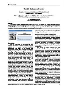
Figure 1(a): A multi storey apartment building constructed with Prefabricated Modular units
Figure 1(b): A prefabricated modular unit being brought to site for assembly
In order to reduce life cycle environmental impacts of buildings, their service life should be extended as much as possible (Lu Aye et al., 2007). The durability of the structure plays an important role. For example, the structure of commercial buildings in Australia is typically designed to last 100 years; however the average service life of buildings in the Melbourne CBD is closer to 25 years. This figure is based on the observation that most major refurbishments or
deconstructions of office buildings in Melbourne happen within the first 20 to 30 years of the building’s life. The life cycle environmental impacts can be significantly cut down if the structural components of a building are designed to be durable and reusable. Innovative prefabricated modular structures could play a major role in achieving this through improved structural connections that ensure easy disassembling thus efficient reusability. Waste minimisation strategies have widely been in use for some time in the construction industry. Many studies measure waste from construction sites on the basis of either volume or mass, to gauge the effect on disposal costs (Johnston et al., 1995; Graham et al., 1996; Faniran et al., 1998). The savings from reducing waste can be best measured in terms of the environment by considering their embodied impacts (Thormark, 2000). This study aims to quantify the potential life cycle environmental benefits of prefabricated modular structures in order to determine whether this form of construction provides improved energy performance over conventional construction methods.
1.2 Innovative Prefabricated Modular Structures – Structural Aspects These are prefabricated systems that provide the structure of the building complete with the architectural finishes and services, ready for assembly on site. It is suitable for both medium and high use. As modern architecture comes with innovative designs, the system does not rely on a fixed module. A building designer is free to layout a building in the conventional manner to suit a client’s desire and the requirements of the market. The building is then adjusted and divided into units that are in width and length suitable for transportation and lifting into position by crane on site. The features of such building units (modules) are as follows:
The units can incorporate all components of a building including stairs, lift shafts, facades, corridors and services
The units are constructed in a production facility. A unit’s length, width and height can vary from project to project
There is minimal work on site to complete the buildings as the façade and interiors themselves form part of units
Many developments in the range of 8 to 25 stories are already underway in Melbourne, Australia using this technology. 1.2.1 Load Transfer Mechanisms Our initial studies show that the vertical load transferring mechanism can be achieved with four or more structural steel or concrete columns fixed to the exterior of each unit. Lateral loads can be transferred through the roof and floor plates to the bracing elements. These bracing elements could consist of the wall trusses or diaphragm walls, framed cores within selected modules or
conventional lateral supporting concrete or steel framed core system, subject to the height of the building. Vertical loads are transferred through the wall plates to vertical load bearing columns connected to each boxed frame.
Figure 2: A 3D perspective of a building module frame (steel module) 1.2.2 Other Features Footings The footings of any building assembled in this way will have footings constructed in the conventional manner to suit the site conditions and height of the building. However, the size and capacity of the footings will be reduced and therefore less costly than a conventionally constructed concrete building due to lower weights associated with this form of construction. Car Parks Where car parks are required, they can be constructed in concrete in the conventional manner, as this type of construction is best suited. A transfer level can be formed at the top level of the car park, as required to transfer the loads from the units to the car park structure. In this way the most economical and efficient layout of structural members can be achieved. Roofs The roofs of the units are fabricated as a separate framed section and is lifted into position on the topmost units and connected in the same way as the connections between the units. The roof is formed with short stub columns that align with the columns below, steel side beams and steel
purlin. A parapet is formed around the perimeter of each unit such that the entire roof is made up of unit size sections that are each drained independently. After installation a metal capping is fitted over all the parapets to waterproof the junctions between the units. The covering to the roof can either be steel roof sheeting with conventional gutters and flashings or sheeted with plywood and a bituminous waterproof membrane. Additional finishes such as concrete pavers or timber decking can be added to created rooftop terraces. Plant platforms and walkways can be added as required. Drainage can be achieved with downpipes from the gutters in a steel sheeted roof or from downpipes connected to roof outlets. The downpipes will generally be positioned on the external faces of the building. Drainage to balconies is achieved in the same way as a membrane roof with the downpipes connected to balcony drains. It is common for the balcony drains to align with the roof outlets so a single downpipe connecting the roof outlet and balcony drains, in each run, can be used. Services Services and Fittings are included in each unit and are fitted off from the fixtures and fittings to a central point suitable for connection after installation. Installation of the main risers (water, gas, sewer, etc) and cabling (electrical, phone and data, etc) can be carried out on site in the conventional way. Plant equipment is set up in much the same way as in conventional buildings. The type of plant is determined by the building size, type of services available or required and availability.
1.3 Embodied Energy The term ‘Embodied Energy’ can be explained as the energy consumed during extraction, processing, manufacturing, and transportation at all stages (Boustead et al. 1979). Embodied energy and natural resources are conserved when energy intensive materials are used efficiently and waste is minimised (Lawson, 1996). Embodied energy is thus a useful indicator of resource value and environmental impacts. Previous studies have focused on the recycling potential of construction waste and demolition materials, valuing waste in terms of embodied energy (Thormark, 2000). However, there is an absence of detailed scientific research or case studies dealing with the overall environmental benefits of prefabrication (Jaillon et al., 2009), particularly the embodied energy savings resulting from waste reduction and the improved efficiency of material usage. Guggemos and Horvath (2005) have identified and quantified the energy required for the construction of two office buildings, one with a structural steel frame and the other with a cast in place concrete frame. The study included the energy associated with material extraction, construction, use, maintenance, and end-of-life demolition. The findings revealed that the total life cycle energy use of both steel and concrete framed buildings were comparable. An analysis of the construction elements showed that the concrete slabs contributed the greatest to the overall embodied energy of the studied buildings. A further study of office buildings has supported this finding, indicating that the reinforced concrete in slabs and beams alone can contribute from 59 to 67% of a building’s total embodied energy (Dimoudi et al., 2008).
1.3.1 Embodied Energy Analysis Methods At best, studies that have compared conventional and prefabricated construction methods in the past, have used incomplete methods of embodied energy analysis, known to exclude up to 87% of the energy requirements associated with construction (Crawford, 2005; Crawford, 2006). Never before has a model utilising a systemically complete system boundary been used to assess and compare the embodied energy associated with these two forms of construction. Due mainly to the known deficiencies in the methods of analysis used, the knowledge gained from previous studies provides little support to industry in their need for environmental comparisons between different construction approaches in order to inform design decision-making. A traditional process analysis approach to embodied energy assessment suffers from a systemic incompleteness, which is due to the delineation of the assessed system by the finite boundary, and the omission of contributions outside this boundary. The arbitrary truncation of the system boundary also limits the comparability of results. Hybrid analysis methods have been developed in an attempt to minimise the limitations and errors of traditional embodied energy assessment methods. National average statistics that model the financial flows between sectors of the economy, referred to as input-output (I-O) data, can be used to fill the gaps that are caused by system boundary incompleteness (Proops, 1977). These hybrid methods combine process data and I-O data in a variety of formats (Treloar, 1997; Suh et al., 2002). The hybrid model developed by Treloar (2002) (known as input-output-based hybrid analysis), addresses many of the problems associated with traditional assessment approaches by starting with a disaggregated I-O model to which available process data is integrated. This avoids the possibility for truncation errors. Using the approach developed by Treloar (2002), the current study extends on similar previous studies by providing a more comprehensive assessment of the energy embodied in conventional concrete and prefabricated steel construction approaches (resolving substantially the issue of system boundary incompleteness). The information provided by this study will facilitate the design decision-making process and the environmental benefits of prefabrication will be able to be better evaluated in order to create buildings that are optimised for environmental performance.
2. Life Cycle Energy Analysis - Methodology A multi-residential building has been used as a case study to assess the life cycle energy performance of prefabricated steel and timber constructions. This section outlines the case study building that was analysed and the methods used to assess the life cycle energy requirements associated with both conventional concrete and prefabricated steel and timber construction approaches for this building.
2.1 Case Study Building This study involved an assessment of the embodied and operational energy associated with a multi-residential building, for three varying construction approaches, a prefabricated modular steel structure and a prefabricated modular timber structure with a conventional concrete structure used for comparative purposes. The building modelled has a gross floor area of 3,943 m2 with a total of 63 apartments consisting of 58 single-storey and five double-storey apartments. The first six floors of the building each consist of 9 single-storey apartments (Figure 3) and the seventh floor consists of four single-storey and five double-storey apartments. The floor area of the single-storey and double-storey apartments is 63 and 118 m2, respectively. The ground floor consists of seven tenancies together with other utilities. The ground floor and the sub-structure were not considered in this study. The details of the external/internal walls and the floor/ceiling panels are for each scenario is by element (Table 1).
Figure 3: Standard floor plan for single-storey apartments (FKA, 2009)
Table 1: A summary of the types of disaster in Europe 1990-99 Steel building Exterior wall
Concrete building 1) 1.6mm thick Corten steel panel 2) 90mm thick Cellulose Insulation 3) 50mm studs 4) Plaster boards (13mm)
1) Precast Concrete 2) 90mm thick Cellulose Insulation 3) Timber Frame 4) Plaster boards (13mm)
Timber building 1) 20mm thick Timber Planks 2) 90mm thick Cellulose Insulation 3) 50mm studs 4) Plaster boards (13mm)
Internal wall 1) Stud wall (50x50x3 SHS) 2) Plaster boards (13mm)
1)Timber frame (50x50 Sections) 2) Plaster boards (13mm)
1)Timber frame (50x50 Sections) 2) Plaster boards (13 mm)
1) Plywood flooring (19mm) 2) 2.4mm thick Corten steel panel
1) Plywood flooring (19mm) 2) 100mm thick Cellulose Insulation 3) Reinforced Concrete slab (32 MPa)
1) Plywood flooring (19mm) 2) 20mm thick Timber Planks
Floor
3) 100mm thick Cellulose insulation
3) 100mm thick Cellulose Insulation
2.2 Embodied Energy Analysis Embodied energy accounts for the energy consumed during the manufacture of products and materials, including those resulting from the manufacture of goods and services used during this process. For example, the energy embodied in steel products, typically comprise energy for iron ore extraction, transporting and processing the iron ore, manufacturing the steel products and delivery to site. Energy is also embodied in goods and services, including capital, utilised during these processes, and so forth. Many factors (including technology, fuel supply structures, region, product specification and analysis method) can result in considerable variability in embodied energy data. The embodied energy assessment for the case study building was performed using an input-output-based hybrid analysis. This method is applied using an I-O model of Australian energy use, developed by Professor Lenzen, Department of Physics, The University of Sydney. The base I-O data was taken from the Australian National Accounts (Australian Bureau of Statistics, 2003) and combined with energy intensity factors by fuel type. The combination of these two sources comprises the I-O model. The model includes the value of capital purchased in previous-years, and capital imported from other countries, amortised over the capital item’s life (as described and analysed in Lenzen & Treloar, 2004). Capital refers to the equipment and machinery used to make or transport products. The I-O model was used as the basis for the embodied energy analysis of the case study building. The best available process data was incorporated for specific material manufacturers as per the input-output-based hybrid method (Treloar, 1997). Process specific data for the energy from the manufacture of specific materials was obtained from the latest available SimaPro Australian database (Grant, 2002).
Table 2: Densities and embodied energy intensities of basic construction materials Density (kg/m3)
Material
Unit
Embodied energy intensity (GJ/unit)
2400
m3
5.48
Concrete (50 MPa)
2400
3
m
8.55
Structural steel
7850
t
85.46
Concrete (30 MPa)
Glass (4 mm)
Plywood Aluminium Timber (softwood) MDF Mortar Ceramic tiles
1.72
m
2
2.17
m
2
2.07
540
m
3
10.92
2700
t
2600
Cellulose insulation (R2.5, 100 mm) Plasterboard (10 mm)
m
2
43 950
252.60
m
3
10.92
500
m
3
30.35
1900
t
700
1700
m
2.00 2
2.93
Source: Treloar and Crawford (2009)
The calculation of the energy embodied in the two structural systems for the case study building was based on the embodied energy intensities from Table 2, which includes the energy from fossil fuel consumption. These intensities were calculated using the input-output-based hybrid method, combining available process data for the specific materials, with I-O data. The quantities of the materials used for each construction system for the case study building were determined and multiplied by their respective embodied energy intensities. The sum of these results gave the total embodied energy for each structural system. The proportion of materials available for reuse for both construction approaches was determined and the energy embodied in these materials was also calculated using the above approach. The energy associated with the end-of-life demolition, disposal and reuse processes (e.g. making good) of materials has not been included in this study. Crowther (1999) has shown that the energy associated with this stage of a building’s life represents less than 1% of the building’s life cycle energy requirement.
2.3 Operational energy analysis The operational energy associated with the case study building was estimated using TRNSYS simulation software. Based on the characteristics of the building as well as assumed heating and cooling schedules. The simulation was performed using the Melbourne TMY data developed and provided by Morrison and Litvak (1994). The simulation was performed on an hourly basis for a period of one year maintaining an indoor air temperature range of 21-24C. The detailed occupational schedules and gains were not considered in this study.
The seasonal average heat pump Coefficient of Performance (COP) values of Heating = 3.0 and Cooling = 2.2 were used in estimating the electrical energy requirement from the heating and cooling load outputs.
2.4 Life cycle energy The life cycle energy requirements associated with the case study building over a 50-year period were calculated for all structural scenarios. This was achieved by combining the initial embodied energy values with total estimated operational energy requirements over 50 years, assuming no heat pump system efficiency losses or improvements over time. Embodied energy associated with replacement of materials and building components over the life of the building was not included in the analysis, although during the life of a building this energy can represent up to 32% of its initial embodied energy (Treloar, 2000). The extent of this depends on a number of factors, including the useful life of the building and the anticipated life of the individual materials or components. It was assumed that material replacement rates for both building scenarios would be similar as they relate mainly to external and internal finishes and not to the building structure. Despite this, the study represents a much more comprehensive approach to the embodied energy assessment of a multi-residential building than has been previously undertaken.
2.5 Greenhouse gas emissions Whilst calculating energy consumption is important in identifying areas where significant reductions in consumption may be achieved, energy consumption figures alone do not necessarily give a good indication of the environmental impacts associated with this consumption. The same quantity of energy, but from different fuel sources (including coal, natural gas, wind and solar) will result in a wide range of impacts on the environment. The greenhouse gas (GHG) emissions produced from the combustion of fossil fuels, which supply over 86% of global energy needs, is one of the main contributors to the world’s key current environmental issue, global warming. The quantification of GHG emissions from consumed energy is seen as a good indicator of the overall environmental impact resulting from energy consumption. 2.5.1 Embodied energy-related emissions Due to the difficulties associated with determining the proportion of embodied energy supplied by the various fuel types within all of the processes involved in manufacturing and supplying the components of the case study building, an average emissions factor of 60 kg CO2-e per GJ of energy has been used to calculate the greenhouse gas emissions related to the embodied energy of all construction types (Treloar, 2000).
2.5.2 Operational energy-related emissions Energy required for heating and cooling was assumed to be provided by brown coal-fired electricity, common for residential buildings in Victoria, Australia. Using the primary energy factor (3.5 for electricity in Victoria, Australia [Treloar, 1998]), estimated operational energy figures were converted to primary energy terms to account for the impacts associated with the energy production. Emissions factor of 1.35 kg CO2-e per kWh of electricity (Department of Climate Change, 2008) was used to estimate the greenhouse gas emissions from the electricity consumption figures.
3. Results and Discussion This section presents the results and discussion of the life cycle energy analysis of the case study building for prefabricated steel and timber, and concrete construction approaches.
3.1 Embodied energy analysis This section presents the results of the embodied energy analysis of the case study building for both concrete and prefabricated steel construction approaches. Table 3 provides a breakdown of the total building material volume, mass and embodied energy for the major construction elements, for all construction types. While the total mass of the concrete building is over four times greater than that of the prefabricated steel building, the total embodied energy in the steel building is about 50% higher than that of the concrete building. This is predominately due to the much more energy intensive processes involved in steel manufacture as compared to concrete production, for an equivalent functional unit (in this case a building’s structure). For the timber building with steel columns and beams the total embodied energy is about 10% higher than that of concrete building. The comparison of material volume for all construction approaches. This shows that the external walls, followed by the floor panels, contribute the greatest to the overall material volume for all building construction approaches, representing 49%, 47% and 39% of total material volume, for steel, timber and concrete respectively. These areas are therefore where greatest waste avoidance benefits can be achieved, through extending material life and maximising eventual reuse, minimising the impact on landfill. For the case study building, the total embodied energy breaks down to 14.4, 10.5, 9.6 GJ per m2 of floor area for the prefabricated steel, prefabricated timber and concrete construction systems, respectively. As the energy embodied in the prefabricated steel system is significantly higher than for the conventional concrete system, the environmental benefits of maximising material life and potential for material reuse for the steel scenario are also greater.
Table 3: Volume, mass and embodied energy breakdown of case study building for prefabricated steel, concrete and timber scenarios, by element Element
Mass (t)
Volume (m3)
Embodied energy (GJ)
Steel
Concrete
Timber
Steel
Concrete
Timber
Concrete
Timber
18.2
91.3
18.9
142.6
228.6
148.4
13 402
2 106
13 948
External walls
565.4
1 114.9
653.2
227.9
1 153.0
234.8
12 457
7 792
7 445
Floor panels
305.9
941.5
381.3
132.4
1 116.2
111.7
9 802
9 226
2 775
5.8
5.8
5.8
15.8
15.8
15.8
4 378
4 378
4 378
143.9
568.8
222.8
184.0
1 184.1
235.3
8 179
9 564
4 103
40.8
50.1
40.8
56.8
44.8
56.8
2 799
1 016
2 799
1.8
57.1
12.2
13.9
139.5
95.8
1 307
853
1 470
Doors & windows
30.1
33.1
30.1
29.5
23.7
29.5
3 799
2 733
3 799
Floor tiling
19.3
19.3
19.3
34.7
34.7
34.7
280
280
280
0.5
3.6
0.5
2.0
8.9
2.0
186
60
186
12.7
-
12.7
31.0
-
31.0
189
-
189
1 144
2 886
1 398
871
3 949
996
56 778
38 008
41 373
0.29
0.73
0.35
0.22
1.00
0.25
14.40
9.64
10.49
Columns & beams
External cladding Ceiling Internal walls Roof
Staircase First floor* Total Total per m2
Steel
*First floor slab is included in floor panel element for concrete building scenario
3.2 Operational energy analysis This section details the annual operational energy requirements associated with the case study building for all construction types investigated. The TRNSYS simulation performed to determine the operational energy required for each zone to maintain an indoor air temperature between 21-24 C (Figure 4).
Figure 4: Typical TRNSYS output: indoor air temperature (21-24C) vs ambient air temperature The heating and cooling load patterns behave similarly for all the construction types investigated. The estimated heating and cooling loads were used to calculate operational energy consumption for all construction scenarios by using the heat pump seasonal average COP values described earlier. The annual operational energy for the building clearly indicates that in Melbourne the heating energy requirements are much greater than cooling energy requirements for residential buildings (Figure 5). There is slight difference in total heating and cooling energy requirements among the three building construction types investigated. The difference shown in operational energy is due to the difference in the thermal mass and heat transfer characteristics of the construction materials selected.
Figure 5: Annual operational energy requirements of the three construction types, per m2 of floor area
3.3 Life cycle energy The embodied and annual operational energy requirements calculated above were combined to determine the life cycle energy requirements of the case study building for both concrete and prefabricated steel construction types over a 50-year period. The findings are presented in Table 4 and Figure 6. The life cycle energy requirements were shown to be greater for the prefabricated steel scenario at 36 GJ/m2, compared to 30 GJ/m2 for the concrete scenario. For all scenarios the total heating and cooling energy represents a larger component of the total life cycle energy requirements than do the embodied energy requirements. Table 4: Total life cycle energy over 50 years (NLA = 3943 m2) Building type
Embodied energy (GJ)
HVAC energy over 50 years (GJ) Heating
Cooling
Life cycle energy over 50 years (GJ)
Total
Steel
56 778
68 036
17 049
85 086
141 864
Concrete
38 008
66 753
13 126
79 879
117 887
Timber
41 373
67 180
16 265
83 445
124 818
Figure 6: Life cycle energy requirements of the three construction types over 50 year
3.4 Life cycle greenhouse gas emissions The embodied and annual heating and cooling electricity requirements estimated above were used to determine the associated greenhouse gas emissions for the case study building using primary energy and greenhouse emission factors for Melbourne, Victoria.
3.4.1 Embodied energy-related emissions The greenhouse gas emissions associated with the energy embodied in the building were 3407, 2482 and 2281 t CO2-e for the prefabricated steel, prefabricated timber and concrete building types respectively. The elemental breakdown of embodied greenhouse gas emissions for all construction systems is shown in Figure 7.
Figure 7: Embodied greenhouse gas emissions of the three building types, by element It is evident that the steel framed building has about 50% more embodied greenhouse gas emissions compared to the concrete framed alternative. The embodied greenhouse emissions per square metre of floor area are 864, 630 and 578 kg CO2-e for the steel, timber and concrete construction systems, respectively. 3.4.2 Operational energy-related emissions The annual heating and cooling energy-related greenhouse emissions are shown in Table 5. This clearly indicates that there is no big difference in the operational energy-related emissions between the concrete and prefabricated steel and timber buildings. The difference is attributed by the differences in heat transfer characteristics and slight difference in thermal mass. It should be noted that the bulk insulation levels for all building types meet the Building Code of Australia’s minimum requirements. Table 5: Annual operational energy-related greenhouse gas emissions for concrete and prefabricated steel building types (NLA = 3943 m2) Structure type
Annual operational emissions (kg CO2-e/m2)
Annual operational emissions (t CO2-e) Heating
Cooling
Total
Heating
Cooling
Total
Steel
145.8
36.5
182.3
37.0
9.3
46.2
Concrete
143.0
28.1
171.2
36.3
7.1
43.4
Timber
144.0
34.9
178.8
36.5
8.8
45.3
Table 6: Total life cycle greenhouse emissions over 50 years (NLA = 3943 m2) Building type
Embodied emissions (t CO2-e)
Operational emissions over 50 years (t CO2-e) Heating
Cooling
Total
Life cycle emissions over 50 years (t CO2-e)
Steel
3 407
7 290
1 827
9 117
12 524
Concrete
2 280
7 152
1 406
8 558
10 838
Timber
2 482
7 198
1 734
8 941
11 423
Table 6 shows the total life cycle greenhouse emissions for a 50-year life span for each construction type for the case study building. This indicates that the concrete structure results in a 13% less life cycle greenhouse emissions than prefabricated steel building. The embodied emissions contribute between 21 and 27% of the total life cycle emissions. Including the greenhouse gas emissions associated with maintenance and replacement of materials and components over this period would further demonstrate the importance and significance of this embodied greenhouse gas emissions component. The following section quantifies the materials likely to be reused at the end of the building’s useful life and the potential embodied energy and material savings from this reuse, as opposed to the use of virgin materials.
3.5 Material reuse benefits Reuse of construction materials can lead to significant resource savings together with other environmental benefits from a reduction in waste disposed of in landfill and the energy required for the production of virgin materials. A major advantage of prefabricated steel and timber construction is the ability for construction elements to be disassembled at the end of their useful life and reused in a new building. On the other hand, whilst concrete can be recycled as aggregate in new concrete, it is typically not possible to reuse structural elements from one building in a subsequent building. The potential material resource and embodied energy savings possible from the reuse of materials for both concrete and steel buildings are shown in Table 7, based on assumptions of the likely materials and respective quantities available for reuse. Whilst the concrete construction system accounts for a greater volume of material than the steel system, and thus a greater potential for reducing the quantity of waste sent to landfill, the potential for embodied energy savings from the reuse of materials is significantly greater for the prefabricated steel construction system.
Table 7: Total volume, mass and embodied energy of concrete and prefabricated steel building scenarios, with quantity and proportion of potential savings from the reuse of materials
Initial total Quantity reused Saving (%)
Steel 1 144 60 5.3 Steel 56 778
Volume (m3) Concrete 2 886 20 0.7
Timber 1 398 35
Steel 871 441
2.5
50.7
Mass (t) Concrete 3 949 87 2.2
Timber 996 335 35.6
Embodied energy (GJ) Concrete Timber 38 008 41 373
46 157
12 259
28 584
81.3
32.3
69.1
The potential future reuse of a material can never be guaranteed. For this reason it does not make sense to allocate any environmental credit to its initial use. However, if a material can be reused after its initial use, the building in which the material is reused should be credited with the embodied energy saving resulting from the avoidance of the energy required for processing and manufacturing new virgin materials (Treloar et al., 2001). Designers should always attempt to use materials that have the potential to be reused rather than disposed of at the end of a building’s useful life. Table 7 shows the comparison between the proportions of total material volume, mass and embodied energy savings from the reuse of building components for the concrete, steel and timber building scenarios. The study revealed that the reuse of even a small proportion (by volume) of embodied energy intensive materials at the end of the building’s useful life can result in a substantial saving in embodied energy for both concrete and prefabricated steel and timber systems. The proportion of embodied energy able to be saved by reusing existing materials in a new building is up to 81.3% or 46 157 GJ for the prefabricated steel building, up to 69.1% or 28 584 GJ for the prefabricated timber building and up to 32.3% or 12 259 GJ for a concrete building. It should be noted that these figures do not take into account the ability to recycle materials, such as concrete into aggregate, for use in new buildings which can also save substantial quantities of virgin materials and embodied energy.
4. Conclusions This study has assessed the life cycle energy requirements of three forms of construction for a multi-residential building, conventional concrete construction, prefabricated steel construction and prefabricated timber construction to determine the environmental benefits offered by modularised prefabrications. This comparison used an innovative hybrid embodied energy assessment approach that has never before been used in this manner. The study has shown that the prefabricated steel system results in a significant reduction in the consumption of raw materials of up to 50.7% by weight. Despite this, the energy embodied in the prefabricated steel building is up to 50% greater than that for the concrete building. However, the additional benefit
of the prefabricated system is the ability to reuse a significant proportion of the structure at the end of the building’s life. This may result in a significant reduction in waste being sent to landfill and reduced requirements for additional virgin materials. At the end of the building’s useful life, up to 81.3% of the embodied energy of the initial steel building can be saved by reusing the main steel structure of the prefabricated modules and other components in another new building. There was also shown to be only a minor variance in the operational energy requirements associated with the construction types. Additionally, the embodied energy component for all construction types investigated was shown to represent at least 32% of the total life cycle primary energy requirements. This reinforces the importance of building embodied energy, particularly as rapid improvements are made in buildings operational efficiency performance, further increasing the relative significance of embodied energy. From a life cycle energy perspective, over a 50-year period, the prefabricated steel scenario was shown to consume more energy than for conventional concrete construction. However, despite this the study has clearly indicated that prefabricated construction is capable of providing improved environmental performance over conventional construction methods if they are initially designed to be reused, either adaptively or through disassembly. The reuse of materials may reduce the space required for landfill and the requirement for additional virgin raw materials. The choice of materials in the construction of buildings has a significant impact on the embodied energy requirements of construction. However, embodied energy should be optimised in the broader life cycle context, considering also the operational, recurrent, maintenance and end-of-life energy requirements and impacts associated with buildings.
References Australian Bureau of Statistics (2003) National Accounts 2000-01, Cat. No. 5206.0, Australian Bureau of Statistics, Canberra. Boustead, I. and Hancock, G.F. (1979) Handbook of Industrial Energy Analysis, Ellis Horwood Limited, Chichester. CIRIA (1999) Standardisation and Pre-assembly Adding Value to Construction Projects, Report 176, CIRIA, London, UK. Crawford, R.H. (2005) Validation of the Use of Input-Output Data for Embodied Energy Analysis of the Australian Construction Industry, Journal of Construction Research, 6(1), 71-90. Crawford, R.H. (2008) Validation of a Hybrid Life-Cycle Inventory Analysis Method, Journal of Environmental Management, 88(3), 496-506. Crowther, P. (1999) Design for Disassembly to Recover Embodied Energy, Proceedings of the 16th International Conference on Passive and Low Energy Architecture, Melbourne, September.
Department of Climate Change (2008) National Greenhouse and Energy Reporting (Measurement) Determination 2008, Commonwealth of Australia, Canberra. Dimoudi, A. and Tompa, C. (2008) Energy and Environmental Indicators Related to Construction of Office Buildings, Resources, Conservation and Recycling, 53, 86-95. Faniran, O.O. and Caban, G. (1998) Minimising Waste on Construction Project Sites, Engineering, Construction and Architectural Management, 5(2), 182-188. FKA (2009) Architectural Plans of Russell Place Development, Fender Katsilidis Architects. Graham, P. and Smithers, G. (1996) Construction Waste Minimisation for Australian Residential Development, Asia Pacific Journal of Building and Construction Management, 2(1), 14-19. Grant, T. (2002) Australian Material Inventory Database of Life Cycle Assessment Values for Materials, RMIT, Melbourne. Guggemos, A.A. & Horvath, A. (2005) Comparison of Environmental Effects of Steel- and Concrete-Framed Buildings, Journal of Infrastructure Systems, June, 93-101. Jaillon, L., Poon, C.S. and Chiang, Y.H. (2009) Quantifying the Waste Reduction Potential of Using Prefabrication in Building Construction in Hong Kong, Waste Management, 29(1), 309320. Johnston, H. and Minks, W.R. (1995) Cost Effective Waste Minimisation for Construction Manager, Cost Engineering, 37(1), 31-39. Lawson, W.R. (1996) Building Materials, Energy and the Environment: Towards Ecologically Sustainable Development, The Royal Australian Institute of Architects, Red Hill, 135p. Lenzen, M. and Treloar, G.J. (2004) Endogenising Capital - A Comparison of Two Methods, Journal of Applied Input-Output Analysis, 10(December), 1-11. Lu Aye, Mirza, M.A. and Robinson, J.R.W. (2007) Life Cycle Greenhouse Gas Emissions of Building and Construction: an Indicator for Sustainability, Proceedings of the MDCMS 1 Vietnam First International Conference on Modern Design, Construction and Maintenance of Structures, 10-11 December 2007, Hanoi. pp. S1-S6. Morrison, G.L. and Litvak, A. (1994) Condensed Solar Radiation Data Base for Australia, Report 1988/FMT/1 (Kensington, University of New South Wales), 16p. Osmani, M., Glass, J. and Price, A. (2006) Architect and Contractor Attitudes to Waste Minimisation, Waste and Resource Management, 2(1), 65-72.
Productivity Commission (2006) Waste Management, Report no. 38, Canberra. Proops, J.L.R. (1977) Input-Output Analysis and Energy Intensities: A Comparison of Methodologies, Applied Mathematical Modelling, 1(March), 181-186. Skoyles, E.R. and Skoyles, J.R. (1985) Waste Prevention on Site, Mitchell’s Professional Library, London. Suh, S. and Huppes, G. (2002) Missing Inventory Estimation Tool Using Input-Output Analysis, International Journal of Life Cycle Assessment, 7(3), 134-140. Tatum, C.B., Vanegas, J.A. and Williams, J.M. (1986) Constructability Improvement Using Prefabrication, Pre-assembly and Modularisation, Technical Report 297, Construction Industry Institute, Standford, USA. Thormark, C. (2000) Including Recycling Potential in Energy Use into the Life Cycle of Buildings, Building Research and Information, 28(3), 176-183. Treloar, G.J. (1997) Extracting Embodied Energy Paths from Input-Output Tables: Towards an Input-Output-Based Hybrid Energy Analysis Method, Economic Systems Research, 9(4), 375391. Treloar, G.J. (1998) A Comprehensive Embodied Energy Analysis Framework, Ph.D. Thesis, Deakin University, Geelong, 286p. Treloar, G.J. (2000) Streamlined Life Cycle Assessment of Domestic Structural Wall Members, Journal of Construction Research, 1, 69-76. Treloar, G.J. and Crawford, R.H. (2009) Database of embodied energy and water values for materials, The University of Melbourne, Melbourne. Treloar, G.J., Gupta, H., Love, P.E.D. and Nguyen, B. (2003) An Analysis of Factors Influencing Waste Minimisation and Use of Recycled Materials for the Construction of Residential Buildings, Management of Environmental Quality, 14(1), 134-145. Treloar, G.J., Love, P.E.D. and Holt, G.D. (2001) Using National Input-Output Data for Embodied Energy Analysis of Individual Residential Buildings, Construction Management and Economics, 19, 49-61.