compared with the best known erasure codes â LT codes. Index TermsâLow Density Parity Check Codes, LT codes,. Wireless Sensor Networks, Network ...
1
INPoD: In-Network Processing over Sensor Networks based on Code Design Kiran Misra, Shirish Karande, and Hayder Radha, Senior Member, IEEE
Abstract—In this paper, we develop a joint Network Coding (NC)-channel coding error-resilient sensor-network approach that performs In-Network Processing based on channel code Design (INPoD). INPoD represents a major development of an underlying framework for designing Code-on-Network-Graph (CNG). CNG (and hence INPoD) maps variable nodes of Low Density Parity Check (LDPC) codes onto sensor nodes, and consequently translates check equations (used in linear algebraic LDPC codes) into in-network processing. INPoD/CNG codes not only improve capacity, but are also resilient to errors in noisy environments. In absence of INPoD, basic CNG employs standard LDPC codes while assuming the underlying sensor network is capable of supporting the degree distribution dictated by these codes. In practice, however, we usually have the network topology pre-determined by the placement of the sensors, and hence we are constrained to map a code onto a given topology. In this paper, we specifically address this problem, and propose the INPoD framework, which enables the use of LDPC design tools in the design of CNG for a given sensor network topology. We formulate the design of CNG, as a convex optimization problem, which determines the best codes to be used, given the underlying network connectivity and channel conditions. Specifically, we use density evolution to design degree distributions which controls the performance of the joint NCchannel code CNG. We also give a code construction algorithm, which achieves a designed degree distribution. We show that well-designed INPoD provide gains of 1.5 to 2.5 dB, when compared with the best known erasure codes – LT codes. Index Terms—Low Density Parity Check Codes, LT codes, Wireless Sensor Networks, Network Coding
I. INTRODUCTION
R
ELIABLE transmission of data collected by a largescale sensor networks poses many unique challenges. Network-Coding (NC) [3] achieves capacities higher than traditional routing algorithms [1][2], making them a prime candidate for large-scale data transmissions. Moreover, the broadcast-nature of wireless channels in sensor networks makes a strong case for use of NC in Wireless Sensor Networks (WSN). The basic philosophy of NC is to enable transmission of The authors are with the Electrical and Computer Engineering Department, Michigan State University, East Lansing, MI 488241226 USA. (e-mail: {misrakir, karandes, radha}@egr.msu.edu). This work was supported in part by NSF Award CCF-0515253, NSF Award CNS-0430436, MEDC Grant GR-296, and unrestricted gift from Microsoft Research.
the information via multiple paths, while making efficient use of the available bandwidth with the intermediate coding nodes. Initial efforts in NC required knowledge of complete network topology, however, in [4][5] Ho et. al. proposed a decentralized approach, and derived performance bounds on randomized NC. These randomized network codes, exceeded the performance of randomized routing algorithms. However, these codes are not robust to errors, as seen in wireless environments. In [6] Bao et. al. formulated the NC problem as a joint network-channel coding problem which overcomes this drawback, and allows the construction of joint NC-channel codes which can operate even in noisy environments. It was shown that the algebraic operations (at the intermediate nodes) of NC correspond to the check equations of a linear algebraic channel code. This unique perspective allows us to map the sensor network nodes (more specifically the data they transmit) to the variable nodes of channel code (Figure 1). This in turn permits the information received at the sink to be processed using well-known channel decoding algorithms. In this paper, we provide key contributions to the notion of mapping channel Code-on-Network-Graph (CNG). Under basic CNG, the mapping of variable nodes, of Low Density Parity Check (LDPC) codes onto sensor nodes takes place without considering crucial constraints imposed by the underlying sensor network topology. Consequently, we develop a joint NC-channel coding CNG approach that performs In-Network Processing based on channel code Design (INPoD) that addresses key constraints including topology constraints as explained further below. (For the remainder of the paper, a joint CNG code design that addresses these constraints is synonymous with an INPoD code.) It is known that, channel codes (when properly designed) are robust to erasures as well as errors, making CNG resilient to noise and applicable for wide-range of sensor networks. Current literature [6][7] use standard channel codes in their work, which assume that the underlying sensor network is capable of supporting the topology dictated by these channel codes. However, in real-world scenarios, the underlying topology is often
2
Check Nodes
ρ
PA = P0 ⊗ λ ( RA −1 )
(
RA = Γ −1 ρ Γ ( P0 ⊗ λ ( RA −1 ) )
)
……….
λ Variable Nodes Figure 1: Belief propagation algorithm for LDPC codes
pre-determined by the placement of the sensors, and we are required to determine a code which could be mapped to the given topology. In this paper, we do precisely that, and formulate the design of CNG network codes as a channel-coding design problem, constrained by the underlying sensor network topology and relay channel conditions. In our problem formulation we consider finite neighborhood sizes, while designing the joint NCchannel coding CNG codes. To the best of our knowledge this is the first attempt to include topological constraints while performing code design. Furthermore, we present an algorithm to construct CNG given a degree distribution, on the underlying sensor network. We show that dense sensor networks in general perform better than sparse networks for the same degree distribution. We also demonstrate that the joint CNG designed by our proposed framework (which considers underlying network connectivity) gives degree distributions, which have superior performance when compared to existing channel codes – LT codes. We exploit the analogous behavior of network codes and low-density parity-checks (LDPC) codes in achieving lower outage rates, i.e. the rate at which data-bits are lost in the WSN. Although, there are many methods for designing LDPC codes [10]-[17], we concentrate our efforts on using density evolution [10][14] for network code design, due to their higher accuracy in predicting the average behavior of an LDPC ensemble, and also because of their utility in designing extremely good channel codes. Section II of this paper describes how to convert an arbitrary NC problem into a channel coding problem. More specifically we describe how the XOR operations in NC can be represented as check equations of the bipartite graph of LDPC codes. XORing is a common technique employed in NC, when the network nodes are devices with low-complexity [23]. In section III, we look at how density evolution is employed to analyze the performance of the degree distributions used in Belief
Propagation Algorithm (BPA). The choice of variable (λ ) and check ( ρ ) degree distribution is restricted by the connectivity of the underlying WSN, whereas the channel code rate ( R ) is determined by the behavior of the relay network. Section IV analyzes the channel as seen by the sink, and determines bounds on the channel code rate R . We next define a homogeneous sensor network in section V, and give an algorithm to construct the parity generator matrix G constrained by the graph connectivity. Section VI gives lower bounds for successful code construction. These bounds must be satisfied to get close to the designed parity degree distribution, and to guarantee coverage (i.e. all datanodes participate in forming at least one parity-bit). In section VII, we give the mathematical formulation of the optimization problem for a general sensor network. We discuss the optimization issues involved, and suggest heuristics for good initial guesses. Finally we compare the outage rates for channel codes with LT degree distribution [18], to the designed degree distribution in VIII and present our conclusions in IX.
II. CONVERTING NETWORK CODING TO CHANNEL CODING In NC the intermediate nodes of a network perform linear algebraic operations on the received data, before forwarding them to their neighbors. These operations can be represented by a global matrix at the sink. As long as, the linear algebraic operations result in a global matrix which is invertible, the transmitted data can be recovered successfully at the sink. Typically, linear algebraic operations can result in data in higher Galois fields, however, since we restrict our attention to XORs, we can say without loss of generality the data in the sensor networks is binary. This XORing of bits can be represented as check equations in a belief propagation graph, transforming network codes into a belief network. Figure 2 illustrates such an example. Part a) of the figure, represents the following NC operations:
3 s1
Parity bits
∑λ
Check nodes
i =1
+
+
v1
n
s2
v2 Data bits
v3
v1
v2
v3
s1
s2
Variable nodes
(a) (b) Figure 2: Converting network coding operations into a Belief Network for LDPC decoding
v1 ⊕ v2 ⊕ v3 = s1
(II.1) v2 ⊕ v3 = s2 where, ⊕ represents componentwise modulo-2 addition or XORing. The left side of the equation represents data received by a node, whereas the right side of the equation represents data obtained after XORing, which is forwarded to the downstream nodes. Equation (II.1) can be rewritten as: v1 ⊕ v2 ⊕ v3 ⊕ s1 = 0 (II.2) v2 ⊕ v3 ⊕ s2 = 0 This corresponds to the bipartite graph shown in Figure 2b) with zero-syndrome. As can be seen, the incoming data-bits and the parity-bit generated by NC get mapped to the variables nodes of the belief network. There exists a relationship between the node-degree distributions of network-code to the degree distributions of the belief network. Specifically, if n represents the maximum degree a data-node can take, and m represents the maximum degree for a parity node, and if the data and parity node degree distributions are θ = {θ1 ,θ 2 ,...,θ n } and φ = {φ1 ,φ2 ,..., φm } respectively, then: λ = {λ1 , λ2 ,..., λn } = R *{θ1 − 1 + 1/ R,θ 2 ,θ 3 ,...,θ n }
ρ = {ρ 2 , ρ3 ,..., ρ m +1} = {φ1 ,φ2 ,...,φm } …(II.3) where, θ i is the proportion of data nodes with degree i
φi is the proportion of parity nodes with degree i λi is the proportion of variable nodes with degree i ρi is the proportion of check nodes with degree i R is the code rate Since the above vectors essentially represent the probability distributions, we have the following additional constraints on the degree distributions:
i
=1
m +1
∑ρ i=2
i
=1
n
∑θ i =1
i
=1
m
∑φ i =1
i
=1
(II.4)
The sink then uses BPA on the resulting graph, to perform decoding. The BPA iteratively passes messages between the variable-nodes, corresponding to the codeword side, and the check-nodes, corresponding to the check-equations, as shown in Figure 1. The algorithm stops when all the checks are satisfied, i.e. when a valid codeword is reached. The mapping translates the inversion operation (of the global matrix) in NC to decoding using BPA. The design of network codes can now be posed as the design of the bipartite graph shown in Figure 2b). Invertibility of the global matrix in NC, translates to determination of a graph with near full-rank incidence matrix. This incidence matrix is also called the parity check matrix H and has the general form (where K is the number of data-bits): ⎧⎡ ⎤ ⎪ ⎢1 0 . 1 ⎥ ⎪⎢ ⎥ ⎪ ⎢0 1 . 0 (II.5) H = M checks ⎨ I M ×M ⎥ ⎢. . . . ⎥ ⎪⎢ ⎥ ⎪ ⎢1 0 . 1 ⎥ ⎪ ⎢ �� �
⎥⎦ ⎩ ⎣ K columns The degree distribution of the bipartite graph represented by H , and shown in Figure 1 plays a pivotal role in determining the performance of the proposed system. A more detailed look at its analysis is given in section III. III. ANALYSIS OF BELIEF PROPAGATION ALGORITHM USING DENSITY EVOLUTION The performance of the BPA can be determined by calculating the fraction of incorrect messages passed from the variable node to the check nodes at the A − th iteration, assuming that the graph does not contain cycles of length 2A or less. The cycle-free assumption, for A iterations of the decoder, is necessary to assume independence between incoming messages. Independence in turn, implies that the summation of message at variable and check-nodes, translates to convolution of their probability distributions, making it easier to keep track of the evolution of the message densities. This technique of evaluating code performance by tracking evolution of message densities is labeled density evolution [13]. The evolution of message densities from check-nodes to variable-nodes can be succinctly represented by the following equation:
(
RA = Γ −1 ρ Γ ( P0 ⊗ λ ( RA −1 ) )
where,
)
(III.1)
4
RA − represents the probability distribution of messages from the check nodes to variable nodes after A iterations. P0 − represents the probability distribution of messages received from the symmetric relay channel. λ = {λ1 , λ2 ,..., λn } , where λi is the proportion of edges connected to degree i variable nodes, and
∑
n i =1
λi = 1
ρ = {ρ 2 , ρ3 ,..., ρm +1} , where ρi is the proportion of edges connected to degree i check nodes, and
∑
m +1 i =2
ρi = 1
⊗ − represents convolution Γ = Γ −1 − is change of variable operation associated with the function Ψ ( x) = log ( (e x + 1) (e x − 1) )
λ ( x) = ∑ ∀i λi x ⊗i −1 ρ ( x) = ∑ ∀i ρi x ⊗i −1 Note, here the degree distributions used have an edge perspective, while equation (II.3) uses the node perspective. The following equations, allow conversions between the two perspectives [14]:
λi =
λi i ∑ ∀j λ j j
λi =
i λi ∑ ∀j j λ j
ρi =
ρi i ∑ ∀j ρ j j
ρi =
i ρi ∑ ∀j j ρ j
Similar to equation (III.1), the message densities from variable-nodes to check-nodes can be calculated using: PA = P0 ⊗ λ ( RA −1 ) (III.2) where, PA − represents the probability distribution of messages from variable to check nodes after A iterations. Density evolution is usually carried out for the all-zero codeword, since the performance of the decoder is assumed to be invariant under codeword translation [13]. Now, the fraction of incorrect messages from the
variable nodes to the check nodes, after A iterations, can be determined using: 0
Pe A = ∫ PA ( x)dx −∞
(III.3)
The above quantity forms the objective function to be minimized in the code design problem. Choosing degree distributions which minimize PeA , result in channel codes, which minimize the outage rate in the WSN. A more detailed discussion on density evolution for LDPC codes is contained in [12][13]. IV. NETWORK MODEL Figure 3 shows the network model, where the whitenodes represent the sensor nodes, collecting data, and the black-node represents a network of relay nodes forwarding information to the sink. In the very first iteration of data-transmission, all the sensor nodes transmit their data to their neighboring nodes. These data-bits are then XORed by the sensors using the rules defined in the generator matrix G (constructed by the algorithm described in section V). The XORed bits are then transmitted to the sink (by the first node f selected for parity formation, in the code construction algorithm) via the relay nodes. Since only the XORed parity-bits are transmitted to the sink, the data-bits are effectively erased. Also, for our analysis we assume that the relay channel can introduce errors while forwarding the transmitted bits. More specifically, the relay channel is chosen to be a channel with Additive White Gaussian Noise (AWGN). The overall channel as seen by the sink is a mixture of the erasure channel (for data-bits) and the Gaussian channel. A. Determining the code rate to be used for the mixed channel Shannon’s Noisy Channel Coding Theorem states that given a noisy channel with capacity C , data can be transmitted over the channel with an arbitrarily small probability of error, so long as the information rate (channel code rate R ) is less then channel capacity C [19]. The capacity of the mixed channel is determined by the following equation: C = C AWGN ( M / N ) + CERASURE ( K / N ) (IV.1) = CAWGN (1 − R ) + CERASURE R bits/symbol where, C AWGN is the Capacity of the AWGN channel.
Sensor nodes Relay nodes Figure 3: Network Model
CERASURE is the Capacity of the erasure channel. N is the number of bits in the codeword. M is the number of parity bits. K is the number of data bits.
5
We assume that the parity bits are transmitted through the relay channel using BPSK modulation and the deviation of the AWGN is σ . Then we have the following capacity expressions [19]:
( (
(
C AWGN = CBSC 0.5 1 + erf −1 σ 2
)))
(IV.2)
CERASURE = 1 − PERASURE where, CBSC ( x) = 1 − ( − x log 2 x − (1 − x) log 2 (1 − x) )
PERASURE = 1 , since only parity bits are transmitted When we substitute the above expressions into equation (IV.1) the second term disappears. After the substitution, we get an expression for capacity of the mixed channel, which still depends on the channel code rate R . Substituting the obtained expression of capacity in the inequality R < C , the condition for asymptotic reliable communication (in noisy channel) can be rewritten as: R < C AWGN (1 + C AWGN ) (IV.3) While designing degree distribution for the mixed channel with Gaussian deviation σ , we pick a code rate which satisfies the inequality given in (IV.3). Note, the channel code rate for a given degree distribution is: R =1−
(∑
m +1 i=2
ρi i
) (∑
n i =1
λi i
)
(IV.4)
This equation is used as a constraint while determining the optimal degree distribution. V. HOMOGENEOUS SENSOR NETWORKS AND THEIR CODE CONSTRUCTION We can convert the sensor network in Figure 3 into a directed graph based on the range of transmission of each node. The out-degree of a sensor node is determined by the number of sensor nodes lying in its transmission range, whereas its in-degree is determined by the number of nodes, able to transmit data to it. The out-degree distribution plays a crucial role in the selection of the data-side degree distribution for NC, whereas the in-degree distribution constraints the choices for parity-side degree distribution. For our analysis, we will consider a homogeneous sensor network, i.e. a network where any sensor node v , will have the same number of nodes | N v | within its transmission range. Also every sensor node has the same number of nodes transmitting to it. This implies that the in-degree and the out-degree of the graph under consideration is the same. As we shall see in section VI, the neighborhood size | N v | plays a critical role in determining the feasibility of the degree distributions
during the optimization process. | N v | also influences the coverage of the sensor-nodes. The system illustrated in Figure 3, can be represented as a line of sensor nodes, with neighboring nodes lying next to each other as shown in Figure 4. We choose this representation for ease in explaining the construction algorithm for the generator matrix G . The choice of a line representation does not result in any loss of generality for the homogeneous sensor network. The range of sensor transmissions determines the size of the neighborhood. The following algorithm lists how we can construct a parity generator matrix G , for the line sensor network given data and parity degree distributions, θ and φ respectively. A. Algorithm to construct Parity Generator Matrix G 1. Create a list LD of data nodes based on θ : a. Set data-node start index s ← 1 , and degree-index i ←1 .
b. Set data-node end index e ← s + round ( Kθ i ) c. Add i copies of each data-node s to e to the list LD . d. Update s ← e + 1 . e. Increment i ← i + 1 . Go to step 1b if all the nonzero elements of data degree distribution θ are not exhausted 2. Create a list LM representing the degree of each parity node as follows: a. Set parity-node start index s ← 1 , and iterator i ←1 b. Set parity-node end index e ← s + round ( M φi ) − 1 c. Set elements s to e of list LM to i ; where i represents the number of data-nodes XORed to generate the parity-bit. d. Update s ← e + 1 . e. Increment i ← i + 1 . Go to step 2b if all the nonzero elements of parity degrees distribution φ are not exhausted 3. Now for each element in LM create a list of associated data-nodes as follows: a. Set parity node index i ← 1 b. Create an empty set of data-nodes d ← {} associated with current parity-node i c. Create a list LDQ of unique data-nodes remaining in LD d. Select one data-node f at random from the list
6
LDQ . Add f to set d : d ← d + { f }
e. Remove
f
from
unique
data-node
list
LDQ ← LDQ − { f }
….. N
f. Determine the neighborhood f , of incoming nodes associated with f and present in list LDQ . Select
the
remaining
randomly from f
N
LM (i ) − 1
data-nodes Figure 4: Step-3 in construction of
and add them to set d .
g. Remove one copy of data-nodes in d from LD h. Update generator matrix G (i ) ← d i. Increment i ← i + 1 . Go to step 3b if all the paritybits have not been created, i.e. all the elements of LM have not been processed. 4. Remove 4-cycles from generator matrix G In step 1, of the algorithm we create a list containing copies of the data-nodes so that the fraction of nodes, having i copies, is equal to θ i . This step ensures that we get close to θ , in the constructed G . In step 2, we determine the degree to be associated with each parityequation such that, the fraction of parity-equations with degree i is φi . Step 3 randomly selects data-nodes to be associated with each parity-equation, the procedure is illustrated in Figure 4. The solid-line represents the randomly selected data-node f , whereas the dashedlines, represent the remaining nodes selected randomly from the neighborhood f N . Steps 1-3 result in a parity generator matrix G which has a distribution ( θ , φ ). However, this random-construction can result in fourcycles in the generator graph. Four-cycles have a detrimental effect on the decoding process at the sink, and therefore are removed in step 4 of the algorithm. This is achieved by deleting edges. If xK ×1 represents the data-vector then the parity-vector pM ×1 can now be generated as follows: pM ×1 = GM × K xK ×1 (V.1) The parity generator matrix G can be transformed into the parity check matrix H using the procedure outlined in section II, and used for belief-propagation decoding at the sink. We must be careful while designing the degree distribution for channels which involve erasures, for the following reason. The formula to calculate the message to be transmitted from the check node c to the variable node v for a log-likelihood belief propagation decoder is given by:
G
⎛ ⎞⎛ ⎛ ⎞⎞ L(c → v) = ⎜⎜ ∏ α a ⎟⎟ ⎜ Ψ ⎜⎜ ∑ Ψ ( β a ) ⎟⎟ ⎟ ⎜ ⎟ ⎠⎠ ⎝ a∈Nc \ v ⎠ ⎝ ⎝ a∈Nc \ v
(V.2)
where,
N c \ v is neighborhood of c in parity check graph H , except the variable node v
α a is the sign of the message coming from variable node a to c .
β a is the magnitude of the message coming from variable node a to c .
(
Ψ ( x) = log ( e x + 1) ( e x − 1)
)
An erased variable node will transmit zero to the check node, at the very first iteration. As can be seen from equation (V.2), if more than one variable node associated with the check node c sends a zero to it, then the check node c will transmit back a zero to all its variable nodes (due to the function Ψ ). In our code formulation all the check nodes of the parity check matrix H are connected to data-bits, which are erased (as per problem definition). If the parity degree distribution φ does not contain a non-zero fraction for degree-one nodes, then all the check-nodes of H , will have at-least two variable nodes with erasures connected to it. Therefore, to jump-start the BPA it is critical that there are some degree-one nodes in φ . These degree-one nodes create a ripple effect [18], i.e. if the data-nodes connected to degree one parity nodes are also connected to another parity node, then the belief of the degree-one parity node ripples down to the other parity-node via the degree-one parity node
degree-two parity node
+
+
v1
v2
Figure 5: Belief ripple from degree-one parity node to degree-two parity node and beyond.
7
common data-node, as shown in Figure 5. If this parity node, in turn has degree-two, then the ripple propagates further to the next data-node. This ripple propagation via degree-one and degree-two parity nodes is essential for successful belief-propagation decoding for channels containing erasures. In fact, we need to make sure that there is at-least a fraction of the parity nodes which have degree-one and degree-two: φ1 > τ 1 (V.3) φ2 > τ 2 For our analysis, we choose this lower bound to be τ 1 = 0.005 , and τ 2 = 0.49 . VI. BOUNDS ON ACHIEVABILITY/COVERAGE While mapping a channel code to the underlying sensor network, the connectivity/topology of the actual network constraints the degree of freedom in selecting data/parity nodes. This constraint is reflected in step 3 of the code construction algorithm given in section V. Based on the graph connectivity we give the following bounds corresponding to the parity and data sides. A. Parity side feasibility bound Let the expected size of the neighborhood in the underlying sensor network be given by μ N . For step 3 in the code construction algorithm to be successful, we need to select a node f , for which: | f n |≥ number of data-nodes required − 1 We relax this constraint to: | N f |≥ number of data-nodes required − 1 (V.4) where, | N f | is the size of incoming-neighborhood of f . If the number of data nodes required is k , the probability of success is given by: P ( success | k ) = 1 − P (| N f |< k − 1)
= 1 − P (| N f |< (1 − δ ) μ N )
(V.5)
where, δ = 1 − (k − 1) μ N Assuming (k − 1) < μ N , the second term in eq. (V.5), can be bounded below, by using Chernoffs lower tailinequality: μN
⎛ ⎞ e −δ P (| N f |< (1 − δ ) μ N ) < ⎜ (V.6) (1−δ ) ⎟ ⎝ (1 − δ ) ⎠ Substituting (V.6) in (V.5) gives the lower bound for probability of success for a particular degree k . Therefore the lower bound on the probability of achieving the parity degree distribution is given by:
P ( success ) =
∑
P (k ) P ( success | k )
∀k non − zero φk
μN ⎛ ⎛ ⎞ e −δ ⎜ P ( success ) > ∑ φk 1 − ⎜ ⎜ ⎝ (1 − δ )(1−δ ) ⎟⎠ ∀k ⎝ φk ≠ 0
⎞ ⎟ ⎟ ⎠
(V.7)
This inequality gives the lower bound on the probability of achieving a given parity distribution. To ensure any degree distribution selected by the optimization algorithm is achievable, we would like the probability of success to be at-least greater than ω1 . We therefore introduce the following inequality as a constraint in the eventual optimization problem: μN ⎛ ⎛ ⎞ ⎞ e −δ ⎜ φ 1 − (V.8) ∑ k ⎜ ⎜ (1 − δ )(1−δ ) ⎟ ⎟⎟ ≥ ω1 ∀k ⎝ ⎠ ⎝ ⎠ φk ≠ 0 We choose ω1 = 0.9 for our analysis. Interestingly, this bound deals only with expectations, and therefore can be applied even to non-homogeneous sensor networks with asymmetric transmission ranges. Due to the relaxation used in (V.4), this is an optimistic bound. B. Data side coverage bound The random construction of code given in section V, can result in parity generator graph G , in which some of the data nodes are left hanging. The BPA cannot recover these unconnected nodes, since the sink does not receive any information about them. The probability that a data node is left hanging depends on the size of the neighborhood (ngbd.) in the homogeneous sensor network. We can determine the probability that the datanode is connected, i.e. selected in step 3 of the construction algorithm as follows: P (data node v selected ) = P( ngbd . selected in which v lies)
(V.9)
* P (v selected | ngbd . selected in which v lies ) Now, P (ngbd . selected in which v lies) (V.10) M = 1 − (1 − (| N v | +1) K ) If the degree of the parity node being formed is k : P (v selected | ngbd . selected in which v lies, k ) (V.11) = k (| N v | +1)
Again we have made use of the following relaxation: | f N |≈| N f |=| N v | . Using (V.11), we obtain:
P (v selected | ngbd . selected in which v lies ) =
∑ φ P(v selected | ngbd . selected in which v lies, k )
∀k φk ≠ 0
k
…(V.12)
8
Substituting (V.12) and (V.10), in (V.9) gives the probability of that an arbitrary node v is connected in the parity generator graph G . This probability is also the probability of successful coverage of sensor nodes, and we therefore introduce the following inequality constraint in the optimization problem formulated in section VII: P (data node v selected ) = P(coverage) ≥ ω 2 (V.13) In our analysis we choose ω 2 = 0.9 .
VIII. EXPERIMENTAL SETUP AND RESULTS
VII. MATHEMATICAL FORMULATION We now setup the optimization problem for a generic non-homogeneous sensor network. We will restrict density evolution analysis to 25 iterations of the BPA. If we let the in-degree distribution of the sensor network be α = {α1 ,α 2 ,...,α n } where α i is the proportion of sensor nodes with in-degree i , and
∑
n
α i = 1 . This defines an
i =1
upper bounds on the fraction of data-nodes with degree as α ilim = ∑ j =i α j . Similarly, if the out-degree n
i
distribution of the sensor network is β = {β1 , β 2 ,..., β m } where β i is the proportion of sensor nodes with indegree i , and
∑
m i =1
set strategy [20], to determine locally optimal solutions. The search-space for degree distributions is highly multimodal and therefore different initial points can result in significantly different degree distributions. One way to overcome getting stuck in local minima is by using techniques such as simulated annealing [21] or evolutionary computation [22]. We plan to explore these advanced techniques in future work.
β i = 1 . This defines an upper bounds
Substituting, the AWGN deviation σ = 0.82 , in equations (IV.2) and (IV.3) results in a channel capacity C ≈ 0.33 as observed by the sink. We therefore design a channel code of rate R = 1/ 3 . In a rate-1/3 code the number of parity-bits generated is twice the number of data-bits. The degree distribution obtained by solving the above optimization problem results, in codes which approach channel capacity, as the number of data-nodes goes to infinity; however there is a caveat to this statement which we shall discuss below. Since we select a finite number of data-nodes in our analysis, there is a loss in coding performance, when compared to asymptotic bounds given by density evolution. The best known codes for erasure channels are LT codes. We select the LT distribution given in [18] as one
on the fraction of parity-nodes with degree i as
Table I: Parity and Data Degree Distributions
β ilim = ∑ j =i β j . The design problem can then be written m
Maximum degree 12
LT derived, max. 12
Maximum degree 6
LT
φ1
0.0048
0.0048
0.0051
0.007969
φ2
0.4900
0.4900
0.4900
0.493570
0.0412
0.166220
as: f (λ , ρ ) = min Pe25 λ,ρ
where,
0 ≤ θi ≤ α
lim i
(V.14)
, ∀1 ≤ i ≤ n
0 ≤ ρ i ≤ β , ∀2 ≤ i ≤ m + 1 Equations (IV.4), (V.3), (V.8) and (V.13), are additional constraints on the optimization problem. The standard deviation of AWGN for which the optimization is carried out is σ = 0.82 , and the neighborhood size for the homogeneous sensor network is assumed to be | N v |= 18 . While performing the optimization we observed that limiting the parity and data degrees to 12, results in the constraints (V.8) and (V.13) being satisfied for the channel code rate R = 1/ 3 . As a rule of thumb, the initial guess value for the optimization problem is setup to be degree distributions, which are close to the desired rate. Moreover, we would like these initial guesses to have low average paritydegree, so that decisions in BPA can be made quickly on the check side. Also average data-degree is chosen to be high, so that the data-nodes receive correct information fairly quickly. We then use sequential quadratic programming method, along with line search and active lim i −1
φ3 φ4
0.0183
0.0068
0.4276
0.072646
φ5
0.0383
0.0239
0.0362
0.082558
φ6
0.0989
φ7
0.0759
φ8
0.0089
φ9
0.056058 0.0021
φ10
0.0496
0.0139
φ11
0.1164
0.1968
φ12
0.1978
0.1628
0.037229
φ19
0.055590
φ65
0.025023
φ66
0.003135
θ6 θ12
1.0000 1.0000
1.0000
1.0000
9
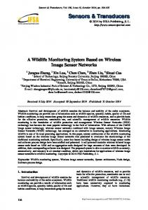
Figure 6: Outage Rate for designed degree distributions and LT distribution for 1000 data-nodes, | N v |= 18
of the distributions for our code construction. The distribution is listed in the fourth column of Table I. For LT-codes, the fraction of parity nodes which correspond to degrees greater than | N v | +1 , are included in degree
| N v | +1 , during code construction. The first three columns of Table I represent the designed degree distributions obtained by solving the optimization algorithm given above. The first column represents the case when the data and parity node degrees are constrained to be less than equal to 12. The constraints (V.8) and (V.13), in the optimization problem, result in this upper bound on degree. For the second column, we artificially constraint the max. degree of the data/parity distributions to 6. This corresponds to a code, where the parity is formed relatively quickly as the receiving node has to wait for a fewer number of incoming informationbits. Again, the third column is a degree distribution whose maximum degree is constrained to 12, however this distribution was arrived at by choosing the truncated LT distribution as the starting point for the optimization algorithm. Figure 6 depicts the performance of these codes over a sensor network containing 1000 data-nodes, and a neighborhood size of | N v |= 18 . As can be seen for an outage rate of less than 0.1 the designed degree distributions have an advantage of about 1.5 dB when compared to the LT degree distribution. Moreover, all the designed codes have nearly identical performance. This suggests that there is considerable flexibility in choice of a good degree distribution for the sensor network. As seen in Figure 6, LT codes which are optimal for erasure channels suffer significantly due to the noise in the relay channel. In general, the outage rate decrease as the SNR of the relay channel goes up. However, we see that the outage rate is not a monotonically decreasing function, and has
Figure 7: Outage Rate for designed degree distributions and LT distribution for 10,000 data-nodes, | N v |= 18
certain artifacts associated with it. This is because the constraints placed on neighborhood size, result in short cycles while constructing the code. Smaller is the ratio of the neighborhood size | N v | to data-bits K , more likely is the probability of getting a short cycles in parity generator graph G . This can be ascertained by examining the expression for probability of seeing a 4cycle in the graph (assuming step-4 in code construction is not carried out): ⎛k⎞ ⎡ ⎤ P (4 cycle exists | φ ,|N v |) ≥ ⎢1 − (1 − z )⎜⎝ 2 ⎟⎠ ⎥ ⎣ ⎦ 2
⎛ ⎞ i , α = ∑ φi ⎜ where, z = e ⎟ , 0