Univ de Toulouse, LAAS, F-31400 Toulouse, France. {oramos ... to let each foot go from its initial to its final position, controlling also the center of mass and the ...
June 11, 2014
13:58
WSPC/INSTRUCTION FILE
walkingRough
International Journal of Humanoid Robotics c World Scientific Publishing Company
TOWARDS REACTIVE VISION-GUIDED WALKING ON ROUGH TERRAIN: AN INVERSE-DYNAMICS BASED APPROACH
Oscar E. Ramos1 , Mauricio Garc´ıa1,2 , Nicolas Mansard1 , Olivier Stasse1 , Jean-Bernard Hayet2 , Philippe Soueres1 1
CNRS, LAAS, 7 avenue du colonel Roche, F-31400 Toulouse, France Univ de Toulouse, LAAS, F-31400 Toulouse, France {oramos, mjgarcia, nmansard, ostasse, soueres}@laas.fr 2
CIMAT, A.C., Jalisco S/N Mineral de Valenciana CP 36240, Guanajuato, Mexico {mjgarciav, jbhayet}@cimat.mx Received 30 June 2013 Revised 11 January 2014 Accepted 17 April 2014
This work presents a method to handle walking on rough terrain using inverse dynamics control and information from a stereo vision system. The ideal trajectories for the center of mass and the next position of the feet are given by a pattern generator. The pattern generator is able to automatically find the footsteps for a given direction. Then, an inverse dynamics control scheme relying on a quadratic programming optimization solver is used to let each foot go from its initial to its final position, controlling also the center of mass and the waist. A 3D model reconstruction of the ground is obtained through the robot cameras located on its head as a stereo vision pair. The model allows the system to know the ground structure where the swinging foot is going to step on. Thus, contact points can be handled to adapt the foot position to the ground conditions. Keywords: Humanoid; Walking; Dynamics; Vision
1. Introduction Center-of-Pressure based walking schemes mainly allow walking on planar homogeneous surfaces.1 Using such schemes, several works have recently succeeded in making real humanoid robots walk on uneven terrain.2,3,4 These are usually adaptations to a horizontally composed plane, or systems where preview control considers information from the current inclination of the upper body. Methods such as the one proposed by Nishiwaki2 use predictive attitude compensation control, adjust the Zero Moment Point (ZMP) reference to repetitive walking, and use gains of impedance to update the desired landing position. Some existing methods like the one proposed by Morisawa,3 Kaneko,4 Ott,5 do not use visual information to guide the foot on the ground. They concentrate on some efficient formulations of the ZMP preview window, and the rejection of error modeling using the robot attitude esti1
June 11, 2014
2
13:58
WSPC/INSTRUCTION FILE
walkingRough
O.Ramos, M.Garc´ıa, N.Mansard, O.Stasse, J-B Hayet, P.Sou` eres
mated by an accelerometer and a gyrometer, to compensate for the roughness of the terrain. By coupling both aspects with the information provided by a portable laser (namely Hokuyo), Nishiwaki2 proposed the current best system implemented on a real humanoid robot. Indeed, HRP-2 is able to cope with gravels, unknown slopes of 10 degrees and so on. Still this approach is based upon a kinematic control scheme driven to regulate global dynamical parameters such as the total angular momentum derivative about the robot Center-of-Mass (CoM). However, this method does not directly handle the dynamics of the robot, and it uses an inverse kinematics scheme where inequalities cannot be formulated. The work presented by Morisawa3 suffers from the same limitation. To address this issue, this paper proposes a control scheme based upon inverse dynamics: the whole dynamics of the robot is considered and because inequalities can be explicitly formulated, it is possible to rely on a balance criteria in its generality. In addition, the work of Nishiwaki pointed out the necessity of handling noise which occurs even with a laser sensor. One problem with current laser sensor technology is time to fly and the weight. A humanoid robot needs a relatively dense reconstruction to elect potential contact points while walking, and fast enough lasers are currently too heavy to be embedded inside a humanoid robot. To reconstruct a surface, 3D information provided either by a Kinect or a stereoscopic system would need to be implemented, but it represents a difficult task both in computer vision and robotics. The problem is that depth or range sensors provide a huge amount of data that has to be processed to get high level information, which makes real time reconstruction difficult. Yet, as mentioned above, a precise dense reconstruction is critical for pattern generation in rough terrains. We have empirically estimated that precision below a few centimeters may cause strong impacts on the robot feet with the floor or, on the contrary, may cause the robot feet to never reach the floor. In either case, the robot may lose balance and fall down. One solution, which is used here, is parallel processing using GPUs that allows to get very efficient 3-D dense reconstruction systems.6,7 This work uses a generic hierarchical optimization solver based on the robot dynamic model to track the position of the CoM and to autonomously control the swinging foot according to the output of a pattern generator. The solver consists of an inverse-dynamics control cascade where motion is represented by tasks. As the foot goes down, possible collisions are detected thanks to the reconstructed map of the terrain which was obtained by the stereo vision system. In this way, collision points are found and handled by the solver, and if necessary, some extremes of the foot are properly taken towards the ground to maximize the support area without losing dynamic balance. An important assumption of this work is that the ground is supposed to remain static. The detection and the geometric reasoning on the foot landing bear some similarity with a parallel work.8 However there is no dynamical consideration and on-line foot-step adaptation.
June 11, 2014
13:58
WSPC/INSTRUCTION FILE
walkingRough
Towards Reactive Vision-guided Walking on Rough Terrain
3
2. Inverse Dynamic Stack of Tasks 2.1. Task Function Approach The task function approach9 (also called operational space approach10 ) is a framework to describe tasks in terms of specific output functions chosen to ease the observation and control of the task to be performed. In the case of robotics, it consists in generating motion based on the definition of different tasks whose control laws are expressed in a subspace of smaller dimension than the full robot state space. Then, these laws are back-projected to the original space. For instance, to raise the foot, the initial and final positions and orientations are used to define the control law, instead of the whole joint space. Formally, let C be the configuration space, M the task space, Tp (M) the tangent space of M, and U an arbitrary control space, linearly linked to the configuration tangent space Tp (C). A task is completely defined if the following three components are specified: • The task function e : C → M. • The reference behavior e˙ ∗ ∈ Tp (M), given by a vector field of M, which is defined as an arbitrary desired behavior for the task velocity e. ˙ • The differential map G : U → Tp (M) relating the task to the control input. The map G defines the direct relation between the reference vector field (e) ˙ and the control space as e˙ + δ = Gu, where u is the control signal and δ is the drift of the task. The control law u∗ satisfying the reference behavior is obtained as u∗ = G# (e˙ ∗ + δ),11 where {.}# is any reflexive generalized inverse. Among the possible inverses, the Moore-Penrose pseudo-inverse is generally chosen, but other inverses (typically a weighted inverse) can also be used. Even though the presented generic formulation directly corresponds to the inverse kinematics, it also covers the inverse dynamics:10 the reference behavior is described by the desired task acceleration (¨ e∗ ), and the control input by the joint torques vector (τ ). In this case, the approach finds the desired torque control input τ ∗ that will generate the reference behavior e¨∗ using any necessary joint accelerations q¨.11 The inverse-dynamics framework is used in this article. 2.2. Inverse Dynamics For a humanoid robot, let n represent the total number of degrees of freedom (DoF) comprising the na actuated DoF and the r non-actuated DoF corresponding to the position and orientation of the robot free-floating body (n = na + r). If the position is represented by Cartesian coordinates and the orientation by Euler angles, which is a typical case, then r = 6. The configuration of the robot will be represented by the generalized coordinates q = [xb qa ]T ∈ Rn , where xb ∈ Rr represents the pose of the robot with respect to the world, and qa ∈ Rna is the angular position of the na actuated joints. Supposing that there are nc points in contact with the
June 11, 2014
4
13:58
WSPC/INSTRUCTION FILE
walkingRough
O.Ramos, M.Garc´ıa, N.Mansard, O.Stasse, J-B Hayet, P.Sou` eres
environment, let xp = [x1 x2 · · · xnc ]T ∈ R3nc represent the contact points in the world frame, and f = [f1 f2 · · · fnc ]T ∈ R3nc the punctual contact forces, with fi acting at xi . For an underactuated robot in contact with the environment, the dynamic equation of the system can be written as A¨ q + b + JcT f = S T τ
(1)
where A ∈ Rn×n is the generalized inertia matrix, b ∈ Rn is the dynamic drift ∂x including Coriolis, centrifugal and gravity forces, Jc = ∂qp ∈ R3nc ×n is the Jacobian of the contact points, τ ∈ Rna is the actuated torque vector, and S = [0 I] ∈ Rna ×n is a matrix that selects the actuated joints (0 ∈ Rna ×r and I ∈ Rna ×na ). Let S n , with elements {snij } = δ(3i − j) where δ is the Kronecker delta function, n be a matrix that selects the normal components so that f ⊥ = S n f and x⊥ p = S xp are the vectors containing only the normal components of f and xp . Considering the “rigid contact point model”, the complementarity conditions to avoid interpenetration are: x ¨⊥ p ≥ 0,
f ⊥ ≥ 0,
⊥ x ¨⊥ = 0. pf
(2)
⊥ = 0), the contact When the first case of the condition is satisfied (¨ x⊥ p ≥ 0 and f breaks and the rigid bodies separate from each other. To guarantee contact persistence, the other condition must be fulfilled. Considering that the contact Jacobian gives the relation x˙ p = Jc q, ˙ this condition states that x ¨⊥ p = 0, or equivalently
Jc q¨ + J˙c q˙ = 0,
(3)
f ⊥ ≥ 0.
(4)
and
If all the contact points lie on the same horizontal plane, Eq. (4) ensures the dynamic balance of the robot since it is a necessary and sufficient condition for the ZMP to be well defined inside the support polygon.11 However, it has been implicitly assumed that the interaction between both rigid bodies presents large friction coefficients so as to neglect friction forces. If these coefficients are not negligible, the conditions can be generalized to friction cones in a straightforward way,12 but this is currently computationally expensive. 2.3. Stack of Tasks The Stack of Tasks (SoT) consists in hierarchically using dedicated tasks for each desired type of motion. A task i consisting of any observable si = si (q) willing to reach a desired s∗i can be specified without loss of generality by the ith task ei = si − s∗i which must tend to zero. At the acceleration level to be used for the dynamic control, the relation between the task space and the joint space becomes: e¨i = J˙i q˙ + Ji q¨ where Ji =
∂ei ∂q
th
is the Jacobian of the i
task.
(5)
June 11, 2014
13:58
WSPC/INSTRUCTION FILE
walkingRough
Towards Reactive Vision-guided Walking on Rough Terrain
5
In this work we use a dynamic SoT in the sense that not only the tasks are taken into account, but also the dynamic model of the robot as well as the contact constraints. The usage of the dynamics of the robot implies the computation of the torques τ and the accelerations q¨ that will be applied to the robot. The contact constraints will force the computation of the desired forces f that are feasible with the motion. Thus, with these formalisms, the operational-space inverse-dynamics problem can be reduced to finding the variables (¨ q , τ , f ) that are consistent with the dynamic equations and minimize the distance to the task reference. The computation of these variables is done using a cascade of Quadratic Programs (QP) that takes into account equalities or inequalities at any level of the hierarchy; then, they can be specified with arbitrary priority. Due to the hierarchical characteristic, this cascade has been referred to as Hierarchical Quadratic Programming (HQP).13 The explicit computation of all the variables (¨ q , τ , f ) has the advantage that forces are obtained in a straightforward way and no consistency verification or projection is necessary to guarantee their feasibility. Also, explicit constraints on each of the variables can be formulated, and either a torque-controlled or a position-controlled robot can be used. Using a lexicographic order, and considering nt tasks of the form (5), the whole dynamic SoT based on the HQP can be summarized as (1) ≺ (3) ≺ (4) ≺ (5)1 ≺ · · · ≺ (5)nt , where the elements on the left of ≺ have higher priority than the elements on the right.
2.4. Condensation To allow for faster computation of the solver, the variables (¨ q , τ , f ) can be decoupled since the space generated by them can be divided in three subspaces, and only two of them are useful for control purposes. The first subspace is the motion space, where joint accelerations (¨ q ) can be freely chosen, and the corresponding forces (f ) and torques (τ ) are accordingly set. The second is the actuation space, where the acceleration is fixed and only forces can be freely chosen given that forces and torques are related. The third space is useless since motion variables can be theoretically chosen, but resulting forces are impractical. The explicit distinction between the actuation space and the motion space can be done by introducing two decoupled spaces.14 This formulation states that the dynamic model as well as the tasks can be reformulated in terms of the bases of the two decoupled spaces, leading to the usage of decoupled variables instead of the original optimization variables. With this modification, a faster computation of the SoT is achieved, since the decoupled spaces are of lower dimension than the original coupled variables. System balance is generally ensured by adding sufficient tasks to fill up the SoT, so that there is no more redundancy to minimize the torques. But if the SoT is not full, a last task of ‘joints friction’ or posture is generally added to complete it.15 Concretely, this formulation14 is used in this work and the results will be briefly summarized here. The dynamic model of the robot, accounting also for kinematic
June 11, 2014
6
13:58
WSPC/INSTRUCTION FILE
walkingRough
O.Ramos, M.Garc´ıa, N.Mansard, O.Stasse, J-B Hayet, P.Sou` eres
contact constraints, can be rewritten as: ¯ + SJ ¯ cT f + SB ¯ −T δc + SB ¯ −T V u = 0 Sb
(6)
¯ T = 0), B is the where the matrix S¯ = [I 0] is defined to cancel out S T (so that SS Cholesky decomposition of the generalized inertia matrix A such that A−1 = BB T , δc = −G+ J˙c q˙ is the contact drift, V is a basis of the kernel of Jc B such that V V T = I − (Jc B)+ (Jc B), and u is a vector in this kernel. With these definitions, tasks in (5) can be expressed as: e¨i = J˙i q˙ + Ji Bδc + Ji BV u.
(7)
Thus, using this formulation, the condensed dynamic SoT for nt tasks can be expressed as (6) ≺ (4) ≺ (7)1 ≺ · · · ≺ (7)i ≺ · · · ≺ (7)nt , using the vector (u, f ) as the optimization variables. The control torque can be obtained as τ = Sb + SJcT f + SB −T (δc + V u).
(8)
The fact of reducing dimensionality while keeping the capabilities of the dedicated HQP solver has been proved to be numerically stable and to allow a fast resolution.14 Some experimental results show about 4ms for typical HRP-2 problems.14 This makes the usage of the decoupled control scheme including the whole robot dynamics with complex set of equality and inequality constraints possible in real time at 200Hz. 3. Pattern Generator 3.1. Model Predictive Control The model predictive control (MPC) assumes that the robot CoM is maintained at a constant height z c , so that its position can be fully represented only by two components (xc , y c ). Since the motion in the horizontal directions (x, y) can be fully decoupled, only the x components will be explicitly described, but the y components are obtained in a similar way. Using a sampling period T , the discrete variable for the position is noted as xck = xc (tk ) = xc (kT ), where k is the k-th sample, and the state variables comprising the position, velocity and acceleration of the CoM are noted as x ˆk = (xck , x˙ ck , x ¨ck ). The ZMP on the ground is represented by (xz , y z ). With this notation, the discrete dynamic system relating the ZMP and the CoM is:1 3 c 2 T xc xk+1 1 T T2 kc T62 ...c x˙ c = (9) 0 1 T x˙ k + 2 x k k+1 x ¨ck x ¨ck+1 0 0 1 T
h
xz = 1 0
−z g
c
c i xk x˙ c . k x ¨ck
(10)
June 11, 2014
13:58
WSPC/INSTRUCTION FILE
walkingRough
Towards Reactive Vision-guided Walking on Rough Terrain
7
Considering a prediction horizon of N samples, and recursively using the previous dynamics, the velocity of the CoM from tk+1 to tk+N can be expressed as16 c x˙ k+1 ... ˆk + Pvu X k (11) X˙ k+1 = ... = Pvs x x˙ ck+N ... ... ... where X k = ( x ck , · · · , x ck+N −1 ) is the jerk of the CoM from time tk to tk+N −1 , and the matrices Pvs and Pvu are given by T 2 /2 0 0 01 T .. .. Pvs = ... ... ... Pvu = . 0 . . (1 + 2N )T 2 /2 · · · T 2 /2
0 1 NT
In the same time horizon, from tk+1 to tk+N , the ZMP is expressed as: z xk+1 ... .. z Xk+1 = . = Pzs x ˆk + Pzu X k
(12)
xzk+N where the matrices Pzs and Pzu are 1 T . . Pzs = .. .. 1 NT
Pzu
T3 6
T2 2
c − zg .. . N 2T 2 zc − 2 g
c
− Tgz .. = . 3 [1 + 3(N − 1) + 3(N − 1)2 ] T6 −
0 .. T zc g
.
···
T3 6
0 .. . −
T zc g
.
We use the pattern generator proposed in17 , which regulates the speed of the CoM and obtains the foot placement as output of the optimization process. The opti... ... mization variable is uk = (X k , Y k , Xkf , Ykf ), where (Xkf , Ykf ) are the positions on the ground of the following m foot steps. In the remaining part of this paper, m = 2. The resulting optimization problem17 is stated as: � α� ˙ ref 2 ref 2 min k Xk+1 − X˙ k+1 k + k Y˙ k+1 − Y˙ k+1 k uk 2 � β� z ref 2 z ref 2 z z + k Xk+1 − Xk+1 k + k Yk+1 − Yk+1 k 2 � ... ... γ + k X k k2 + k Y k k2 (13) 2 where X˙ ref and Y˙ ref are the desired mean values for the speed of the CoM, X z ref , k+1
k+1
k+1
z ref Yk+1 are the references for the ZMP, and α, β, γ are some constants. These ZMP references are not fixed in advance but are permanently recomputed from the feet
June 11, 2014
8
13:58
WSPC/INSTRUCTION FILE
walkingRough
O.Ramos, M.Garc´ıa, N.Mansard, O.Stasse, J-B Hayet, P.Sou` eres
position decided by the algorithm so that the ZMP lies in the middle of the foot. Let (Xkf c , Ykf c ) be the current position of the foot on the ground. Then, the ZMP references are given by: z ref c Xk+1 = Uk+1 Xkf c + Uk+1 Xkf
(14)
z ref Yk+1
(15)
=
c Uk+1 Ykf c
+
Uk+1 Ykf
c where Uk+1 and Uk+1 describe the time at which the feet are in contact along the c preview window. Uk+1 is always equal to 1 at the beginning of the preview window because it is the current robot support foot. Thus, if ck is the remaining number of iterations for the current robot support foot, and sl is the necessary number of iterations to realize a step, then � ck sl N −sl−ck �T � ck N −ck �T 0 1 0 c Uk+1 = 1 0 , Uk+1 = ck sl N −sl−ck 0 0 1
. . 0}]. where 1n = [1 . . 1}] and 0n = [0 | .{z | .{z n 1’s
n 0’s
For sake of space, the constraints related to the single support phase, which ensure that the ZMP remains inside the support polygon, are only briefly described. These are expressed as: � � � � z x − xf ≤ b(θ) (16) dx (θ) dy (θ) zy − yf where (xf , y f ) is the foot position, θ is its orientation, dx (θ), dy (θ) are column vectors containing the x, y coordinates of the normal vectors to the feet edges, and b(θ) is the column vector containing their position with a security margin. More details about the formulation of the double support phase are available in 17 . 3.2. Foot Compliance The pattern generator presented in the previous section assumes co-planar footsteps and a CoM trajectory that is restricted to a plane.1 Given a certain CoM reference velocity it generates feet trajectories, ZMP trajectories, and a CoM trajectory which, all together, generate a balanced motion for an inverted pendulum. To generate whole-body trajectories, one approach18 is to use tasks for the CoM, and for the feet to follow the given trajectories in a perfect way and in open loop (eventually using a stabilizing method5 ). If some irregularity on the horizontal surface is found, the control system is likely to fail, the robot will not be able to keep its balance and it will fall down. One of the main objectives of this proposed control scheme is to allow the foot to be compliant with respect to irregularities or roughness in the terrain. That is, if an irregularity is found, the foot should not try to push on it due to the pattern generator specification, but it should be able to comply, and adapt itself to this irregularity by properly rotating about some axis. This compliance will allow the robot to use the pattern generator to walk on rough
June 11, 2014
13:58
WSPC/INSTRUCTION FILE
walkingRough
Towards Reactive Vision-guided Walking on Rough Terrain
9
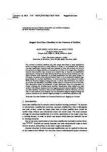
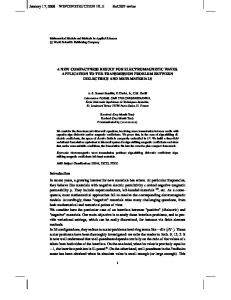
Fig. 1: Contact surfaces with different contact point numbers (from 5 to 2)
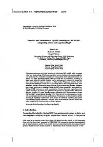
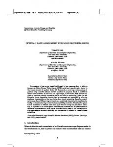
surfaces without losing balance. More specifically the compliance is at the task level and not at the mechanical level to avoid additional control for the passive material. The approach assumes that collision detection is available and that the robot can know the exact position of the points in contact with the ground, as well as the forces at those points at every instant of time.19 With the encoders and the Inertial Measurement Unit (IMU) information, this allows to reconstruct the component xb of the generalized coordinates. The number of points is specified in terms of the vertices of the convex hull formed by all the points belonging to the contact area, as Fig. 1 shows. The foot follows the steps defined by the pattern generator, which assumed a horizontal surface. However, when it is moving down to the ground and it finds some contact point (generated by the irregular ground or by a small obstacle whose size is assumed to be smaller than the step height) it will instantaneously stop its motion downwards to comply with the irregularity that was found. The following cases might happen: • There are three or more contact points • There are two contact points • There is only one contact point If there are more than three contact points, the foot is assumed to be able to safely step on those points, which will generate the support polygon, and it simply stops its motion. When there are less than 3 contact points, the foot does not continue moving down to the ground but it still needs to move to find at least one more contact to have a consistent support polygon. In this case, if the foot is left uncontrolled after the first contact(s), the dynamics of the whole-body might take the foot to an unstable position. To avoid these instabilities, the foot extremes have to be controlled so that the maximum support polygon is obtained. For a single contact point, the foot is in the situation shown by Fig. 2(a),19 where the single contact point is pc1 and the foot extremes are denoted by pe1 , pe2 , pe3 and pe4 . In this case, four triangles with areas Ai , i = 1, 2, 3, 4, are formed by joining the contact point to two consecutive foot extremes. The area of the triangle formed by the consecutive foot extremes pei and pei+1 is given by Ai = 0.5 k (pc1 − pei ) × (pc1 − pei+1 ) k .
(17)
The triangle with the greatest area will contain the extremes of the foot that are
June 11, 2014
10
13:58
WSPC/INSTRUCTION FILE
walkingRough
O.Ramos, M.Garc´ıa, N.Mansard, O.Stasse, J-B Hayet, P.Sou` eres
(a) 1 contact point
(b) 2 contact points (case 1)
(c) 2 contact points (case 2)
Fig. 2: One or two contact points on the sole of the robot
farther from the contact point, and thus, it is desirable to take those extremes to the ground so that the largest support polygon is obtained. To that end, a task is assigned to each of these extremes controlling only the vertical z position so that they go to the ground. While these points are moving, if a contact point is detected, it is added as a contact to the solver and its position is checked against the points that were going to the ground. Then, the task for the closest extreme is removed, and the foot continues its rotation until another contact point is detected, in which case, the remaining extreme task is removed. If there are only two contact points, there are two possibilities shown in Fig. 2(b) and Fig. 2(c). To obtain the case, a line L is passed through both contact points and the extremes of the foot are determined to lie in one side or on the other side of the line. Let the contact points be pc1 and pc2 , the vector joining these points be v = (vx , vy ) = pc1 − pc2 , and the vector joining one point with one extreme of the foot be vi = (vix , viy ) = pei − pc2 . The idea is to rotate the points so that the line L is aligned with the vertical line. Then, the sign of the arc-tangent can be used to determine the side of the line in which a point lies. The angle that line L must rotate to be aligned with the vertical is θ = atan2(vy , vx ). Then, each vi is rotated by the angle θ as: f vix = vix cos(−θ) − viy sin(−θ),
(18)
f viy = vix sin(−θ) + viy cos(−θ).
(19)
f f After this rotation, the angle to the line is determined as φ = atan2(viy , vix ), the sign of φ indicating whether the point is on one side or the other of line L. If only one point is on one side and three are on the other side (Fig. 2(b)), the three points are taken to the ground. If two points are on each side (Fig. 2c(c)), then, the area of the quadrilateral formed by the contact points and the extremes on each side is computed and the largest area indicates that those extremes are farther and must be taken to the ground. As in the case of a single contact, as soon as a new contact
June 11, 2014
13:58
WSPC/INSTRUCTION FILE
walkingRough
Towards Reactive Vision-guided Walking on Rough Terrain
11
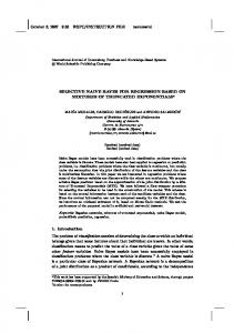
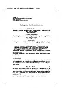
Fig. 3: The upper level specifies a direction of motion. Then the pattern generator finds foot-steps, foot trajectories, a CoM trajectory and a waist trajectory. The Dynamic SoT ensures that the resulting whole-body motion is dynamically consistent with the robot model and its constraints.
appears, it is added as a contact to the solver, and the task for the closest extreme is removed. 3.3. Compliant walking Scheme The heuristics presented in the previous section are used to determine if the foot completely stops its motion or which part of it should be moved towards the ground if there are less than 3 contact points. However, the latter case poses an additional problem for the computation of the Jacobians. The contact forces f can be expressed in terms of a 6D spatial force Φ at some frame of the foot, and it is common to have a direct measurement of the Jacobian relative to this frame, J6 . Then, the contact Jacobian for the contact point is computed as Jc = XJ6 , where X is a matrix involving the cross product with the contact points.14 The problem arises from the fact that if there are only 2 or 1 contact point, X is not full-column rank and the expression for δc in (6) has to be modified to δc = −(XJ6 B)+ X J˙6 q. ˙ After this modification, the SoT described in section 2.4 can be directly used. The compliant walking scheme is obtained by using the output of the pattern generator as input to the inverse dynamics solver as shown in Figure 3. The pattern generator outputs three elements: the trajectory for the CoM, the trajectory for the waist of the robot, and the footprints for each foot. The usage of these elements within the SoT is done with tracking and interpolation tasks. Tracking tasks are 6D operational tasks described with a PD law and aim to control the position and/or orientation of a certain characteristic of the robot (the CoM, or an operational point). The interpolation task is a task that takes an operational point from an initial to a final pose satisfying some fixed (and hard) time constraints, and it is described in Appendix A. The dynamic SoT that is used considers the following tasks: • Tracking task for the x and y components of the CoM trajectory given by the pattern generator, which assumes a constant height. • Tracking task to partially track the waist trajectory. This task controls the height (position in z) of the waist at a certain constant value, as well as the orientation in x, y. As observed, not all the six degrees of freedom are
June 11, 2014
12
13:58
WSPC/INSTRUCTION FILE
walkingRough
O.Ramos, M.Garc´ıa, N.Mansard, O.Stasse, J-B Hayet, P.Sou` eres
controlled, and therefore the name of partial tracking task. • Interpolation task on the swinging foot. The pattern generator gives the footprints on the ground. This task takes the swinging foot from its initial position to its desired final position. There are two interpolation steps: the first task takes the foot from the initial position on the ground to an intermediate position that lies halfway between the initial and final positions with a predetermined height. The second interpolation takes the foot from the intermediate to the final position, if possible. The foot reacts in a compliant way if a contact is detected before arriving to the final position on the ground, as explained in section 3.2. Unlike schemes that only follow the output of the pattern generator using kinematic tasks, the dynamic SoT makes it possible to handle rough surfaces by adding compliance at the task level to the foot at the moment of detection of a contact with the environment. 4. Planning on Dense Surfaces 4.1. Stereo-Reconstruction of Dense Surfaces To perform the dense reconstruction of the floor surface in front of the robot, we rely on a real-time approach similar to the KinectFusion algorithm.6 This approach, originally developed for a RGB-D sensor, models 3-D surfaces as zero-valued level sets of functions defined over the workspace volume. These functions are referred to as Truncated Signed Distance Functions (TSDFs) and they are incrementally built by integrating the depth measurements the sensor provides, frame after frame. TSDFs are defined in the 3D space and their value is the signed distance to the closest obstacle. Here, we extend this approach, initially proposed for RGB-D depth data, to disparity data generated from a stereo head. Although the stereo data is noisier than the one from RGB-D sensors, it is a passive sensor and can be used outdoors in sunlight conditions. Consider, as in the previous sections, that k is a discretized time index. The idea is to update a mathematical representation of the surface through a volumetric TSDF model (defined over a 3D grid), referred to as Fk . The basic steps for integrating one new set of disparity measurements at time k, to update Fk and the corresponding surface, are the following: (1) Filter the raw depth measurements generated from the stereo head (Dk ). For that purpose, here the bilateral filtering was used. (2) From these filtered measurements and the prediction of the estimated surface at the previous step, estimate the transformation between the measured surface and the predicted one using the iterative closest point algorithm (ICP) and update the camera pose. (3) Compute a volumetric grid formed from “local” TSDF values FDk , to which confidence weights WDk are associated, and integrate them into the global vol-
June 11, 2014
13:58
WSPC/INSTRUCTION FILE
walkingRough
Towards Reactive Vision-guided Walking on Rough Terrain
13
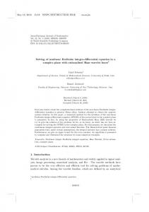
Fig. 4: From a pair of images of the scene in front of the robot (left) a dense disparity map is estimated (middle) and from this disparity map a dense surface integrating the previous frames into the volumetric grid is estimated (right). These images were taken from the HRP-2 stereo vision system with the cameras tilted towards the ground to allow ground reconstruction tasks.4 It is assumed that a mechanism is implemented to make the robot search for traversable areas.20
umetric grid {Fk , Wk }. (4) Predict a new surface for the next iteration by using ray-casting over the zerocrossings of the fused global volumetric grid {Fk , Wk }. The core of this algorithm is the computation and fusion of volumetric grids (i.e., the third step mentioned above). For a 3D point p, expressed in the global frame g, its value in the current local volumetric grid {FDk , WDk } is computed as FDk (p) = Ψ(λ−1 ktg,k − pk − Dk (x)), WDk (p) ∝ cos(θ)/Dk (x),
−1 > > with λ = K [x 1] and ( min(1, µη ) sgn(η) Ψ(η) = null
iff η ≥ −µ otherwise
where µ is a truncation distance (a parameter of the algorithm), and x = −1 π([K, 1]Tg,k p) ∈ R2 is the image projection of p. K is the 3 × 3 matrix of in� � Rg,k tg,k trinsic parameters of the camera, π is the projection operator, Tg,k = is 0 1 the pose of the camera at time k in the global frame g, and θ is the angle between the associated pixel ray direction and the surface normal. The global volumetric grid at time k is formed by the weighted average of all individual volumetric grids up to k − 1. It can be shown that the optimal grid can be incrementally obtained using a simple point-wise on-line weighted average Wk−1 (p)Fk−1 (p) + WDk (p)FDk (p) , Wk−1 (p) + WDk (p) Wk (p) = Wk−1 (p) + WDk (p). Fk (p) =
To use this algorithm with stereo data and generate local data Dk , a disparity map from a pair of rectified images is estimated, from which the depth map Dk is derived assuming that the stereo rig is completely calibrated. The literature of
June 11, 2014
14
13:58
WSPC/INSTRUCTION FILE
walkingRough
O.Ramos, M.Garc´ıa, N.Mansard, O.Stasse, J-B Hayet, P.Sou` eres
ot Fo Fig. 5: Example of a situation handled by our pattern generator with the inverse dynamics stack of tasks. The gray part represents the real environment, and the green line the stereoscopic reconstruction. The foot is in its final position after the adaptation by the proposed method.
algorithms that estimate disparity maps is huge, but since a real time one is needed for this application, the one proposed in21 has been used. This algorithm estimates a piece-wise disparity map using an initial sparse disparity map of high textured points as vertices that define a triangulation of the image. Then, the dense disparity map of each sub-region is estimated using the initial, sparse disparity map as a prior in a probabilistic scheme. The steps of the reconstruction process are illustrated and further described in Fig. 4. 4.2. Planning with the visual reconstruction The visual information obtained from the 3-D vision reconstruction can help the robot pose its feet on the ground as an approximation to the real ground. Due to problems in light conditions (the rough terrain and the obstacles do not always behave as Lambertian surfaces in reality), noise, lack of good features for reconstruction, calibration errors among other problems related to the computer vision system, the reconstruction is not perfect. However, its usage enables the robot to foresee the ground on which it will step and to take the step in a smoother way when close to the irregularities. Consider the scheme in Fig. 5. It shows the real ground in gray, the foot represented by a rectangle, and the 3D visual reconstruction as an approximation to the ground-truth is shown as an irregular pattern above the ground. Without foot compliance, the foot would always try to arrive to the position of the horizontal ground, and in the case shown in the picture, it will evidently fail and make the robot fall down since it would try to continue going downwards even though there is an obstacle that stops it. Adding the foot compliance described in section 3.2, the foot will react to the irregularities and its position will be accordingly modified. However, since the foot initially tries to move until reaching the flat ground, in case of an irregularity, it might find the first contact with a considerable velocity which might make the impact very harsh. To avoid these strong impacts, the visual reconstruction is used. The final position of the foot, set to the ground by the output of the pattern generator, is modified according to the information given by the 3D reconstruction, which is an approximation to the reality. Then, in the interpolation task of the compliant walking scheme (section 3.3) the final position in the ground is modified to be the one ‘predicted’ by the 3D reconstruction. The advantage of this modification
June 11, 2014
13:58
WSPC/INSTRUCTION FILE
walkingRough
Towards Reactive Vision-guided Walking on Rough Terrain
15
is that the foot will arrive to the real irregularity with a lower velocity and the contact impact will be smoother. According to this prediction, the foot is moved but the real contacts from the real environment are taken into account to rotate the foot according to the heuristics for the foot compliance. The visual information only serves as a means to predict the environment but it is the environment itself which will determine the real contact with the foot. 5. Results To validate the proposed scheme, a simulation using the full dynamic model of the HRP-2 robot has been performed on a ground with some irregularities and obstacles. This ground was obtained using the robot cameras. Since structured light RGB-D sensors are not present on the robot, the stereo vision system located in the head has been used to reconstruct the ground. As mentioned above, the robot design is such that these cameras are tilted towards the ground.4 Fig. 6 shows the robot and a rough ground model obtained by visual reconstruction.
Fig. 6: Robot and rough ground model from visual reconstruction
The case where the robot walks on a rough surface is shown in Fig. 7, where the second row depicts a closer view of the corresponding robot foot of the first row. The robot starts from an initial position where both feet are on a flat horizontal surface. Then, the robot performs a step with the right foot. However, before arriving to the theoretical flat ground, a contact is detected and the foot stops its motion down (a),(e). Since only two contact points were detected, the right foot rotates ‘backwards’ as shown in part (b),(f). Then, the left foot performs a step. As with the right foot, the left foot is stopped before arriving to the flat ground since a contact is detected (c),(g). In this case, it rotates to the ‘front’ until it reaches the real ground and more than 2 contact points (d),(h). A similar behavior is obtained for more steps on this type of surface and the feet rotation is achieved according to the heuristics determined in section 3.2.
June 11, 2014
16
13:58
WSPC/INSTRUCTION FILE
walkingRough
O.Ramos, M.Garc´ıa, N.Mansard, O.Stasse, J-B Hayet, P.Sou` eres
(a)
(b)
(c)
(d)
(e)
(f)
(g)
(h)
Fig. 7: HRP-2 walking on a rough surface. The second raw depicts a zoom of the foot and directly corresponds to the first raw. The zoomed view is focused on the right foot for (e), (f), and on the left foot for (g), (h).
In Fig. 8, obstacles are added to the surface. The initial position is shown in (a). Then, the robot raises its right foot and moves it to the next theoretical footprint assuming horizontal flat ground (from the pattern generator). However, the foot finds an obstacle before arriving to the ground. The foot compliance is shown in (b) since the obstacle was detected, and (c) shows the foot rotating to reach a proper support polygon that will make it stable. After this, the robot continues walking. It should be noted that in this case there is only an obstacle for the right foot and the left foot steps on a theoretically flat and horizontal ground. After the step of the left foot, (d) shows again the right foot stepping on the ground. In this case, there is no need to rotate the foot since the supporting surface is enough (the foot steps are almost completely on the obstacle and, thus, a proper support polygon is obtained). Part (e) shows the left foot in the swinging phase and (f) in double support phase. It can be observed that the right foot was properly kept on the obstacle while the right foot was swinging, and the robot balance was not lost. 6. Conclusions The control scheme presented in this paper makes the humanoid robot able to walk on rough terrain by detecting collision points with its stereo vision cameras and moving the foot properly to reach a larger support polygon. This behavior is equivalent to compliance at the foot. The approach has been tested in a simulation environment. Even though surfaces might be rough, the method is limited to horizontal cases and would fail if the ground has a large slope, in which case, a modification in the pattern generator would be needed. However, the presented method provides a very powerful reactive navigation system able to cope with a large set of
June 11, 2014
13:58
WSPC/INSTRUCTION FILE
walkingRough
Towards Reactive Vision-guided Walking on Rough Terrain
(a)
(b)
(c)
(d)
(e)
(f)
17
Fig. 8: HRP-2 walking on an obstacle.
uneven grounds thanks to a very efficient inverse dynamics setup and an automatic way of finding footsteps. The user, or a high decision planner, only needs to provide a direction of motion. Acknowledgments The second author is supported by the grant 263150 from the Mexican National Council of Science and Technology (CONACYT). For this work, the third, fourth and sixth author were supported by grants from the OSEO ROMEO-2 Project, and from the FP7-ICT-2013-10/611909 KOROIBOT project. Appendix A. Interpolation Task The interpolation task is a task that reaches a desired final position and velocity in a specific period of time, assuming that the current position and velocity are known. The basic difference from other types of tasks is the fixed and hard time constraint, and for this reason it is used to drive the swinging foot from its initial to its final position. Let x(t) describe the evolution of a generic feature and let x0 = x(t0 ) and x˙ 0 = x(t ˙ 0 ) denote its position and velocity at the initial time t0 . After a time duration T , the desired position and velocity will be xf = x(t0 + T ) and x˙ f = x(t ˙ 0 + T ). The control is performed via the acceleration x ¨(t) which is set 22 to a linear function of the form: x ¨f − x ¨0 x ¨(t) = x ¨0 + (t − t0 ) (A.1) T
June 11, 2014
18
13:58
WSPC/INSTRUCTION FILE
walkingRough
O.Ramos, M.Garc´ıa, N.Mansard, O.Stasse, J-B Hayet, P.Sou` eres
whose solution leads to quadratic velocity and cubic position trajectories given by: x ¨f − x ¨0 x(t) ˙ = (t − t0 )2 + x ¨0 (t − t0 ) + x˙ 0 (A.2) 2T x ¨0 x ¨f − x ¨0 x(t) = (t − t0 )3 + (t − t0 )2 + x˙ 0 (t − t0 ) + x0 . (A.3) 6T 2 The unknown parameters x ¨0 and x ¨f are obtained from (A.2) and (A.3) at time tf . However, time is not fixed, and as it passes by, the initial position and velocity as well as the time remaining for tf need to be updated, and a new acceleration trajectory (A.1) has to be computed. Then, since (A.1) is permanently updated, only x ¨0 is needed (accelerations at the following instants of time are of no interest), and the dynamic task in (7) is simply defined as e¨∗ = x ¨0 , which can be obtained by solving the system (A.2) and (A.3) at time tf resulting 2 6 (A.4) e¨∗ = x ¨0 = 2 (xf − x0 ) − (x˙ f + 2x˙ 0 ). T T Since only the component at the current time is used but the elements in the whole horizon are needed, this task can also be seen as a preview control task. It should be noted that T becomes smaller after each iteration and is close to zero when the initial time reaches the final time. This situation is handled by keeping the previous value of x ¨0 when T < th , where th is a threshold. In practice, keeping the previous value of the acceleration gives good results. References 1. S. Kajita, F. Kanehiro, K. Kaneko, K. Fujiwara, K. Harada, K. Yokoi, and H. Hirukawa. Biped walking pattern generation by using preview control of zeromoment point. In IEEE/RAS Int. Conf. on Robotics and Automation (ICRA), Taipei, China, 2003. 2. K. Nishiwaki, J. Chestnutt, and S. Kagami. Autonomous navigation of a humanoid robot over unknown rough terrain using a laser range sensor. Int. Journal of Robotics Research (IJRR), 31(11):1251–1262, 2012. 3. M. Morisawa, F. Kanehiro, K. Kaneko, S. Kajita, and K. Yokoi. Reactive biped walking control for a collision of a swinging foot on uneven terrain. In IEEE/RAS Int. Conf. on Humanoid Robotics (Humanoids), pages 768–773, Bled, Slovenia, 2011. 4. K. Kaneko, F. Kanehiro, S. Kajita, H. Hirukawa, T. Kawasaki, M. Hirata, K. Akachi, and T. Isozumi. Humanoid robot hrp-2. In IEEE/RAS Int. Conf. on Robotics and Automation (ICRA), volume 2, pages 1083–1090, New Orleans, LA, USA, 2004. 5. C. Ott, M. A. Roa, and G. Hirzinger. Posture and balance control for biped robots based on contact force optimization. In IEEE/RAS Int. Conf. on Humanoid Robotics (Humanoids), pages 26–33, Bled, Slovenia, 2011. 6. R.A. Newcombe, S. Izadi, O. Hilliges, D. Molyneaux, D. Kim, A.J. Davison, P. Kohli, J. Shotton, S. Hodges, and A. Fitzgibbon. KinectFusion: Real-time dense surface mapping and tracking. In IEEE Int. Symp. on Mixed and Augmented Reality (ISMAR), pages 127–136, Washington, DC, USA, 2011. 7. R.B. Rusu and S. Cousins. 3d is here: Point cloud library (PCL). In IEEE/RAS Int. Conf. on Robotics and Automation (ICRA), pages 1–4, Shanghai, China, 2011. 8. N. Kita, M. Morisawa, and F. Kanehiro. Foot landing state estimation from point cloud at landing place. In IEEE/RAS Int. Conf. on Humanoid Robotics (Humanoids), Atlanta, GA, USA, 2013.
June 11, 2014
13:58
WSPC/INSTRUCTION FILE
walkingRough
Towards Reactive Vision-guided Walking on Rough Terrain
19
9. C. Samson, B. Espiau, and M. Le Borgne. Robot control: the task function approach. Oxford University Press, Oxford, UK, 1991. 10. O. Khatib. A unified approach for motion and force control of robot manipulators: The operational space formulation. IEEE Journal of Robotics and Automation, 3(1):43–53, 1987. 11. L. Saab, O. Ramos, N. Mansard, P. Sou`eres, and J-Y. Fourquet. Dynamic wholebody motion generation under rigid contacts and other unilateral constraints. IEEE Transactions on Robotics, 29(2):346–362, April 2013. 12. C. Collette, A. Micaelli, C. Andriot, and P. Lemerle. Robust balance optimization control of humanoid robots with multiple non coplanar grasps and frictional contacts. In IEEE/RAS Int. Conf. on Robotics and Automation (ICRA), pages 3187–3193, Passadena, CA, USA, 2008. 13. A. Escande, N. Mansard, and P-B. Wieber. Fast Resolution of Hierarchized Inverse Kinematics with Inequality Constraints. In IEEE/RAS Int. Conf. on Robotics and Automation (ICRA), pages 3733–3738, Anchorage, AK, USA, 2010. 14. N. Mansard. A dedicated solver for fast operational-space inverse dynamics. In IEEE/RAS Int. Conf. on Robotics and Automation (ICRA), pages 4943–4949, Minneapolis, MN, USA, 2012. 15. O. Khatib, L. Sentis, J. Park, and J. Warren. Whole body dynamic behavior and control of human-like robots. Int. Journal of Robotics Research (IJRR), 1(1):29–44, 2004. 16. P.-B. Wieber. Trajectory free linear model predictive control for stable walking in the presence of strong perturbations. In IEEE/RAS Int. Conf. on Humanoid Robotics (Humanoids), Genoa, Italy, 2006. 17. A. Herdt, H. Diedam, P.B. Wieber, D. Dimitrov, K. Mombaur, and M. Diehl. Online walking motion generation with automatic footstep placement. Advanced Robotics, 24, 5(6):719–737, 2010. 18. S. Kajita, F. Kanehiro, K. Kaneko, K. Fujiwara, K. Harada, K. Yokoi, and H. Hirukawa. Resolved momentum control: Humanoid motion planning based on the linear and angular momentum. In IEEE/RSJ Int. Conf. on Intelligent Robots and Systems (IROS), pages 1644–1650, Las Vegas, NV, USA, 2003. 19. O. Ramos, N. Mansard, O. Stasse, and P. Soueres. Walking on non-planar surfaces using an inverse dynamic stack of tasks. In IEEE/RAS Int. Conf. on Humanoid Robotics (Humanoids), Osaka, Japan, November 2012. 20. D. Maier, C. Lutz, and M. Bennewitz. Integrated perception, mapping, and footstep planning for humanoid navigation among 3d obstacles. In IEEE/RSJ Int. Conf. on Intelligent Robots and Systems (IROS), 2013. 21. A. Geiger, M. Roser, and R. Urtasun. Efficient large-scale stereo matching. In Asian Conf. on Computer Vision, 2010. 22. M. de Lasa, I. Mordatch, and A. Hertzmann. Feature-Based Locomotion Controllers. ACM Trans. on Graphics, 29(3), 2010.
June 11, 2014
20
13:58
WSPC/INSTRUCTION FILE
walkingRough
O.Ramos, M.Garc´ıa, N.Mansard, O.Stasse, J-B Hayet, P.Sou` eres
Oscar E. Ramos received the Erasmus Mundus M.Sc. degree in computer vision and robotics from Heriot-Watt University, Edinburgh, U.K.; the University of Girona, Girona, Spain; and the University of Bourgogne, Dijon, France. He is currently working towards the Ph.D. degree in robotics with the Laboratory for Analysis and Architecture of Systems (LAAS), Centre National de la Recherche Scientifique (CNRS), University of Toulouse, Toulouse, France. He was previously with the Automation and Robotics Group, Federal University of Rio Grande do Sul, Porto Alegre, Brazil, and with Underwater Robotics Lab, University of Girona. He is involved in the generation of dynamics motion for humanoid robots. Mauricio Garc´ıa is pursuing his M.S. at the Center for Research in Mathematics (CIMAT) in Guanajuato, Mexico. He participated in the 2012 edition of the robocup SPL at Mexico city with the cuauhpipiltin team. He has been an intern at Laboratory for Analysis and Architecture of Systems (LAAS), Centre National de la Recherche Scientifique (CNRS), Toulouse, France in 2012 and 2013 with the GEPETTO Group. During his internships at LAAS-CNRS he has been working on perception using vision for humanoid robots and humanoid locomotion based on vision. His research interests include vision based navigation, stereo vision and 3D reconstruction and humanoid locomotion. Nicolas Mansard received the joint M.Eng. and M.Sc. de´ grees in robotics and image processing from the Ecole Nationale Sup´erieure d’Informatique et de Math´ematiques Appliqu´ees de Grenoble, Grenoble, France, and the University Joseph Fourier, Grenoble, and the Ph.D. degree for his work with the Lagadic Group, Institut National de Recherche en Informatique et en Automatique (INRIA), Rennes, France, in 2006. He spent one year with Stanford University, Stanford, CA, with O. Khatib and one year with the Joint Research Laboratory, National Institute of Advanced Industrial Science and Technologies, Japan, with A. Kheddar. He is currently with the GEPETTO Group, Laboratory for Analysis and Architecture of Systems (LAAS), Centre National de la Recherche Scientifique (CNRS), University of Toulouse,
June 11, 2014
13:58
WSPC/INSTRUCTION FILE
walkingRough
Towards Reactive Vision-guided Walking on Rough Terrain
21
Toulouse, France. His research is concerned with sensor-based robot animation. Olivier Stasse is a senior researcher (CR-1) at CNRS-LAAS, Toulouse. He has been an assistant professor in computer science at the University of Paris 13. He received a Ph.D. in intelligent systems (2000) from the University of Paris 6. His research interests include humanoid robots, and more specifically motion generation motivated by vision. From 2003 to 2011, he was with the Joint French-Japanese Robotics Laboratory (JRL) in Tsukuba, Japan. He has been finalist for the Best Paper Award at ICAR in 2007 and finalist for the Best Video Award at ICRA in 2007, and received the Best Paper Award at ICMA in 2006. Jean-Bernard Hayet graduated from ENSTA (Paris), University of Paris 6 and got his Ph.D. from the University of Toulouse (2003) where he worked at CNRS-LAAS. He was a postdoctoral fellow at the University of Li`ege from 2003 to 2007. Since 2007, he has been working at the Center for Research in Mathematics (CIMAT) in Guanajuato, Mexico. He teaches computer science and his main research interests are in landmarkbased navigation, motion planning with perception constraints, and visual tracking. Philippe Sou` eres received the M.Sc. degree in mathematics, the Ph.D. degree in robotics, and the Habilitation degree, all from the University of Toulouse, Toulouse, France, in 1990, 1993, and 2001, respectively. From 1993 to 1994, he was with the Department of Electrical Engineering and Computer Science, University of California, Berkeley, with Prof. S. Sastry. Since then, he has been involved in different facets of robot perception and control with the Laboratory for Analysis and Architecture of Systems (LAAS), Centre National de la Recherche Scientifique (CNRS), University of Toulouse, Toulouse, France. Since 2003, he has been cooperating with neuroscientists on multisensory and sensorimotor integration. From 2006 to 2007, he was with the Brain and Cognition Research Center (UMR5549), Toulouse. Since 2008, he has been with the GEPETTO Group, LAAS-CNRS, where, since 2010, he has been leading the group. His research interests include control, robot vision and audio, wheeled and flying robots, humanoid systems, and neuroscience.