Standard integral equation (IE) techniques are not easily applied to this problem, since ... field and free space inside S. The continuity of the tangential field is reconstructed ... Downloaded on April 13,2010 at 09:28:33 UTC from IEEE Xplore.
Integral Equation Solution for Truncated Slab Structures by Using a Fringe Current Formulation E. Jplrgensen', A. Toccafondi2, and S. Maci2 * Dept. of Electromagnetic Systems,Tech. Univ. of Denmark,DK-2800 Lyngby, Denmark. 2Dept. of Information Engineering, University of Siena, Via Roma 56, 53100 Siena, Italy.
I
Introduction
Full-wave solutions of truncated dielectric slab problems is interesting for a variety of engineering applications, in particular patch antennas on finite ground planes. For this application a canonical reference solution is that of a semi-infinite slab illuminated by a line source. Standard integral equation (IE)techniques are not easily applied to this problem, since unknown equivalent currents have to be distributed on a semi-infinitedomain. In this paper we present a surface/surface approach, a p plied to an IE which is based on a non conventional formulation. More precise, the unknowns of this IE are the difference between the actual currents and the currents of the infinite structure (without truncation). By invoking the terminology of the Physical Theory of Diffraction, the above mentioned IE will be denoted by Fringe IE (F-E).
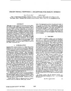
I1 Surface/surface Integral Equations Consider the semi-infinite grounded dielectric slab in Fig.1, with thickness h and permittivity €1. A rectangular coordinate system is introduced with the positive part of the ?-axis orthogonal to the edge and coincident with the top of the substrate, and the Z-axis along the truncation. An observation point is denoted by p. For the sake of simplicity,we assume illumination by an electric line source, placed directly upon the substrate at a distance L from the truncation. The following formulation is especially convenient for a z-invariant excitation, but a linear phase-variation with z can be introduced without conceptual efforts. We invoke the surface equivalence principle on the surface S depicted in Fig.a(a). The top of the substrate and the edge of the truncation are denoted by A and B respectively, and the bottom side of the ground plane with C. We formulate an exterior and an interior equivalent problem, which result in a set of coupled equations by imposing the boundary conditions. First, we consider the exterior problem on Fig.3, where the external region is filled with free-space. We postulate the total field (ECZt,Hezt) outside, and zero field and free space inside S. The continuity of the tangential field is reconstructed by equivalent electric and magnetic surface currents on A and B,and the induced electric surface current on C. We introduce the operator Eo [J,M]to denote the electric field radiated in freespace by the pair (J,M). Continuity of the electric field gives E%&) = E*((p)+Eo [Jzt,MTt]+Eo [Jgt,Mgt]+Eo [JF*,O], p E A , B (1) 0 = E i ( p ) +Eo [JYt,MTt]+Eo [Jgt,Mgt]+Eo [JFt,,0], p E C 0-7803-5639-W99/$10.00 Q 1999 IEEE.
(2)
2546
Authorized licensed use limited to: Danmarks Tekniske Informationscenter. Downloaded on April 13,2010 at 09:28:33 UTC from IEEE Xplore. Restrictions apply.
pig, 1: Truncated tric slab
dielec- Fig. 2: Surface for application of the equivalence principle, (a) truncated structure and (b) infinite structure
E,
P O
R=O
yTgF%zpT,/Ground plane Fig. 4: Interior problem For the interior problem (Fig.4 ), we postulate the exact total field (Einn',Hi"') inside, and zero field outside S. The exterior region can be filled with the dielectric material, and with the virtual continuation of the ground plane. The continuity of the field is reconstructed by distributing equivalent currents on A and B, which radiate in presence of an infinite ground plane. Using the the image principle reduces the problem to currents radiating in a fully homogenous medium. Continuity of the tangential electric field gives
E T B ( p )= E; [Jgt,Mgt] +E; [Jzt,Mgt] , p E A , B
(3)
where ET [J,MI denotes the tangential electric field radiated in a homogenous medium by (J,M), as well as by their image sources. The exterior and interior problems are combined by imposing the field continuity on A and B. We choose to solve for the exterior currents and leave out the ~ )-A x M A , B ( ~when ) , A is the exsuperscript ezt. By observing that E A , B ( = terior normal to S,we obtain from (1)-(3) three IE's with three unknown current components. These coupled equations cannot be solved directly by MOM, due to the infinite dimension of S. Thus, it is convenient to derive a different set of IE's as explained next.
I11 Fringe Integral Equations We now consider the infinite slab depicted in Fig.2(b). The complementary surface to A is given by (5 < 0,y = 0) and is denoted D. Defining exterior and interior problems similar to those for the truncated slab, and imposing the boundary conditions, gives a set of equations similar to the expressions (1)-(3). All quantities in these equations are known, but the information contained in the known solution for the infinite slab, is used when solving the problem of the truncated slab. We use the superscript on the fields and currents of the infinite slab, and subtract the equations for the infinite problem from the corresponding equations for
2547
Authorized licensed use limited to: Danmarks Tekniske Informationscenter. Downloaded on April 13,2010 at 09:28:33 UTC from IEEE Xplore. Restrictions apply.
the finite problem. We introduce the convenient quantities X = X - X p u , where X = E, J, M. Using the linearity of the integral operato's, the outlined procedure leads to five coupled equations, with the unknowns JA,MA,JB, ME and Jc.
EA(^) + Eo [SA,GA]+ Eo [JB,ME]+ Eo [Jc,01 = Eo [JCo0,Mgo]
p E A (4)
-EB(P)+Eo [ ~ A , G+Eo[JB,ME]+Eo[Jc,OI A] =Eo [Jgo,Mgo] > P E B (5) Eo [ j ~ %A] ,
+ Eo [JE, ME]+ Eo [Jc,01 = Eo [Jgoo,Mgo] , P E c
(6)
~ A ( Pi)E; [ j A y GA]+ E; [JB, M E ]= E; [JEo.1Mgo] > P E A (7) EB(P)+ E;
[SA, G A ]
+ E; [JB, ME]= EPBO(P)+ EI [J$o,MP,O] , P E B
(8)
where k : a , ~ ( p=) - A x %A,B(P). Although these five coupled equations look rather complicated, they-are-much more suitable to be solved by MOM than the original ones. Note that (JA,MA)contain only the fringe contributions introduced by the truncation. That is a diffracted space wave we denote as a fringe wave (FW), and 2 surface wave (SW) when this latter is supported by the slab. The surface current Jc on the back side of the ground plane is only due to a FW contribution. The unknowns on B are defined on a small portion of S,and no difficulties occur in their description in the MOM framework. The right sides of the equations can be found by integration of the equivalent PO surface currents on D. These right sides have a difEractive nature, being dominated by the end-point radiation of @go, wgo).
IV Method of Moments solution The coupled equations are solved with a point matching MOM procedure, that is an extension to the one of [l]. In a region close to the truncation, referred to as the MOM region, the unknown currents are expanded in terms of pulse functions. By following the asymptotic behaviour of the fringe fields outside the MOM repion, we define a set of expansion functions with semi-infinitedomains. In particular, on A the unknowns are expanded in terms of basis functions which behave like F W s and SW's. The induced current density on C has no SW component, and can be expanded in terms of a FW expansion function. The forcing terms are calculated by integrating the PO currents, which for a given excitation are known exact from Green's function of the infinite slab.
V Numerical results We compare the results with an alternative IE formulation, which was simultaneously developed by different authors [2][3]. In this alternative formulation, the equivalence principle was invoked on an infinite plane aperture, orthogonal to the slab, and we will denote this as apertureIE (A-IE). The plot in Fig.5 shows the farfield radiation pattern in the I-y plane, normalized with the field radiated by a line source in freespace. The distancebetween the edge and the line source is L = 0.5x0, and we use e, = 2.2. Two different slab thicknesses are considered, h = 0.2X0 and h = 0.3x0, this latter supporting SW propagation. The F-IE (solid line) and the A-IE (dots) predict the same far-field, as expected. For obtaining accurate results, a MOM region of 2 - 3 XO, and 20 pulse expansion functions per wavelength were used.
2548
Authorized licensed use limited to: Danmarks Tekniske Informationscenter. Downloaded on April 13,2010 at 09:28:33 UTC from IEEE Xplore. Restrictions apply.
The plot also shows results obtained with the asymptotic PO formulation in [4] (dashed line). It is worth noting, that PO is in good agreement with the other methods, except for observation in deep shadow region. When a SW is strongly excited (h = 0.3Xo), the PO solution is less accurate, because it describes only the edge diffraction effects of the incident SW excited by the source, but not the backward propagating SW excited at the truncation.
c “a -10
$
-15
-20 J
-25 0
90
180
270
360
4 (deg.) Fig. 5: Normalized far-fieldfor L = 0.5x0, E , = 1.0, h = 0.2Xo and h = 0.3Xo
VI Concluding remarks A fringe integral equation solving procedure has been presented for a truncated grounded dielectric slab. By solving only for the fringe constituents of the fields, which are concentrated in the vicinity of the truncation, the necessary number of unknowns is k e d , independently of the excitation. These features also allow treatment of large h i t e structures, without increasing the number of unknowns. This is accomplished by using the information embedded in the infinite slab Green’s function. The results obtained by the F-IEprocedure has been compared with results of our previous MOM solution [2], showing significant advantages which will be described in details during the oral presentation. References [l] L. S. Andersen, 0. Breinbjerg, and J. T. Moore, YThestandard impedance boundary condition model for coated conductors with edges: A numerical investigation of the accuracy for transverse magnetic polarization,” Journal of Electromagnetic Waves and Applications, vol. 12, pp. 415-446, May 1998. 121 S.Maci, L.Borselli, and A. Cucurachi, “DiEractionfrom a truncated grounded dielectric slab: An efficient numerical analysis,” AP-S Int. Symposium 1998, vol. 4,pp. 2140-2143, July 1998, Atlanta, Georgia. [3]V. Volski and G. Vandenbosch, “The radiation pattern of a magnetic line current placed near the truncation of a dielectricstructure,” JINA 1998, pp. 205-208,November 1998, Nice, France. [4] S. Maci, L. Borselli, and L. Flossi, “Diffraction at the edge of a truncated grounded dielectric slab,” IEEE %ns. Antennas and Propagation, vol. 44,no. 6, pp. 863-873, 1996.
2549
Authorized licensed use limited to: Danmarks Tekniske Informationscenter. Downloaded on April 13,2010 at 09:28:33 UTC from IEEE Xplore. Restrictions apply.