JOURNAL OF SEMICONDUCTOR TECHNOLOGY AND SCIENCE, VOL.14, NO.6, DECEMBER, 2014
http://dx.doi.org/10.5573/JSTS.2014.14.6.755
Integrate-and-Fire Neuron Circuit and Synaptic Device with Floating Body MOSFETs Min-Woo Kwon, Hyungjin Kim, Jungjin Park, and Byung-Gook Park*
Abstract—We propose an integrate-and-fire neuron circuit and synaptic devices with the floating body MOSFETs. The synaptic devices consist of a floating body MOSFET to imitate biological synaptic characteristics. The synaptic learning is performed by hole accumulation. The synaptic device has shortterm and long-term memory in a single silicon device. I&F neuron circuit emulate the biological neuron characteristics such as integration, threshold triggering, output generation, and refractory period, using floating body MOSFET. The neuron circuit sends feedback signal to the synaptic transistor for long-term memory. Index Terms—Integrate-and-fire neuron circuit, synaptic transistor, long and short-term memory, floating body MOSFET
I. INTRODUCTION
Mead [4] is the most representative model of the I&F neuron circuit. This circuit uses two capacitors and six transistors and is very simple and compact for integrating and firing. Many I&F neuron circuits are based on this “Axon-Hillock” model, and provide additional neuron characteristics [5-7]. Most of these circuits are constructed with a capacitor for the integration. Using a capacitor increases power consumption and delay time as well as size of the neuron circuits. These will be a critical problem, if many neuron circuits are integrated on a chip. In this work, we propose a capacitor-less I&F neuron circuit with a floating body MOSFET whose behavior is similar to the 1-transistor DRAM. The capacitor-less 1TDRAM does not need a storage capacitor, since it uses floating body to store holes made by impact ionization. And we propose silicon-based floating-body synaptic transistor (SFST) [8]. The synaptic device has the transition from short-term to long-term memory in a single silicon device.
Until recently, the interest in biological system has increased and many researchers attempt to emulate neural networks that are characterized by parallel processing and low power consumption. Various types of synaptic devices based on resistive switching memory, and neuron circuits using a capacitor have been proposed [1-3]. Integrate-and-fire (I&F) neuron circuit was introduced to emulate biological neuron characteristics. “Axon-Hillock” model shown in Fig. 1 proposed by
Manuscript received May. 12, 2014; accepted Oct. 24, 2014 Inter-university Semiconductor Research Center (ISRC) and Department of Electrical and Computer Engineering, Seoul National University, 1 Gwanak-ro, Gwanak-gu, Seoul 151-742, Republic of Korea E-mail :
[email protected]
Fig. 1. Schematic of the axon-hillock circuit [4].
756
Min-Woo Kwon et al : INTEGRATE-AND-FIRE NEURON CIRCUIT AND SYNAPTIC DEVICE WITH FLOATING BODY MOSFETS
Fig. 2. Circuit diagram of integrated and fire neuron circuit.
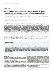
Fig. 4. Simulated hole concentration in the floating body when three-input voltage pulses are applied. When the gate and drain voltages are high, holes are accumulated.
1.0 Input pulse Output pulse
Voltage [V]
0.8 0.6 0.4 0.2
Fig. 3. Device structure of a 4-input floating body MOSFET.
0.0 0.0
4.0x10⁻⁷
8.0x10⁻⁷
1.2x10⁻⁶
Transient time [S]
II. I&F NEURON CIRCUIT 1. Circuit Description The diagram of the proposed I&F neuron circuit is shown in Fig. 2. The circuit comprises a floating body MOSFET, two p-type MOSFETs, and two inverters. Ptype MOSFETs in Fig. 2 plays a role of feedback and makes Node 1 voltage high. The input voltage is applied to the gate, the floating body MOSFET turns on, and Node 1 voltage is decreased. Then, the output node voltage is increased by the inverter, which means the neuron circuit fires. Finally the neuron circuit is back to the initial state by feedback [9]. 2. Multi-gate Floating Body MOSFET The essential characteristics of the biological neuron are spatial and temporal integration, threshold triggering, output generation and refractory period. To emulate these properties, we use the multi-gate floating body MOSFET shown in Fig. 3. The first neuron property is spatial integration. A real
Fig. 5. Repeated low-voltage input pulse simulation result. The holes are accumulated during the first three input pulses, and then the neuron circuit is fired.
neuron has dendrites that connect with many pre-synaptic neurons and receive signals from them. And these signals are integrated. It is spatial integration. To emulate these properties, we use the multi-gate floating body MOSFET for dendrites and integration. When the signals from the many synaptic devices are applied to the gates, the current channel forms below each gate and the holes are made by impact ionization. These holes are integrated in the floating body. Fig. 4 shows the simulation result of the hole concentration in the floating body. The simulation was performed by SILVACO ATLAS. The input voltage is 0.6 V and input pulses are applied to the three gates. Holes are accumulated in the floating body, and the drain current is increased rapidly by the holes. As the drain voltage is 0 V, the holes in the floating body are erased and return to the initial state. The second property is temporal integration. It is performed by the hole integration. This characteristic is
JOURNAL OF SEMICONDUCTOR TECHNOLOGY AND SCIENCE, VOL.14, NO.6, DECEMBER, 2014
757
Fig. 7. Schematic view of (a) short term memory, (b) long term memory mechanism [8].
Fig. 6. Simulated drain current of the floating body MOSFET. Drain current increases very rapidly because of the accumulated holes.
shown in Fig. 5. When the pulse trains from one synaptic device are applied to the same gate, the holes are made by impact ionization at every pulse, and these holes are integrated in the floating body. After several input signals are applied, there are enough holes to generate output voltage. It is temporal integration property. The third property is threshold triggering. The biological neuron has ‘all-or-none’ characteristics. If the accumulated signal is over the threshold potential, the neuron generates output signal to the other synapses. This property is performed by hole concentration in the floating body. As shown in Fig. 4, the holes are increasing exponentially at first. Because the holes make floating body potential lower, the current increases. And this current makes more holes by impact ionization. Because of this positive feedback, the number of holes is increasing very fast at the threshold point and the hole concentration saturates. The difference of the number of holes and drain current between saturation and nonsaturation is about three orders of magnitude as shown in Fig. 6. Therefore, the circuit determines fire-or-not according to the hole concentration. The final property is refractory period. If the neuron generates an output signal, the neuron returns to the initial state, and is not affected by the input signal. Most of I&F neuron circuits use an additional transistor to discharge the capacitor as shown in Fig. 1. But in this neuron circuit using a floating body MOSFET, the holes that accumulated in the floating body, are erased as shown in Fig. 4, when the neuron circuit generates the output signal.
Fig. 8. Circuit description of synapse part and I&F neuron circuit. Each synapse consists of one floating body MOSFET.
III. SYNAPTIC TRANSISTOR AND I&F NEURON CIRCUIT 1. Silicon-based Floating-body Synaptic Transistor Fig. 7 shows the synaptic device structure. The structure is based on a floating body transistor for short term memory, and consists of a back floating gate and a back gate for long term memory. When the input pulse is applied to the gate and drain of the device, the conductance is increased and the threshold voltage is decreased temporarily due to the excess holes made by impact ionization in the floating body as shown in Fig. 7(a). When the holes in the floating body are saturated, newly generated holes are injected into floating gate by negative back gate bias from feedback and the hole injection results in long term memory as shown in Fig. 7(b). 2. Synaptic Transistor and I&F Neuron Circuit The circuit diagram of the synaptic transistor connected with neuron circuit is shown in Fig. 8. The synaptic devices are connected with the neuron circuit.
758
Min-Woo Kwon et al : INTEGRATE-AND-FIRE NEURON CIRCUIT AND SYNAPTIC DEVICE WITH FLOATING BODY MOSFETS
Fig. 9. Simulation result of synaptic device and neuron circuit. Vsyn is increased at every input pulse due to the decreased threshold voltage of the synaptic device. After the synaptic learning, the required number of input pulses to generate neuron circuit output (Vout) is reduced.
The pre-synaptic input is applied to the gate and drain of the synapse and the source of the synapse is connected to the gate of the neuron circuit. And Node 2 of the neuron circuit is connected to the back gate of the synaptic transistor for long term memory. As the input pulse is applied to the gate and drain of the synaptic transistor, the holes are accumulated by impact ionization in the floating body of the synaptic transistor. So current drivability is increased, and the threshold voltage is decreased temporarily. Therefore, the amplitude of the voltage transferred by the synaptic transistor is increased in every input pulse. This result is shown in Fig. 9. The voltage of the source of synaptic device, Vsyn in Fig. 8, is increased by the input pulse. It means that the synaptic device learns through experience. Before synaptic device learning, the neuron circuit requires many input pulses to generate output voltage. But, after the synaptic device learning, the neuron circuit needs just one or two input pulses for firing. And the feedback voltage, from Node 2 of the neuron circuit to the back gate of the synaptic transistor, should be negative in order to inject holes into the back floating gate of the synaptic device for long term memory. So the second inverter in Fig. 8 is modified to connect negative VDD. Fig. 10 shows the modified inverter and simulation result.
Fig. 10. Structure of the modified inverter and the simulation result. The NMOS has high body doping for negative bias. The negative voltage applied to the back gate in the synaptic device for long term memory.
circuit with a multi-gate floating body MOSFET and synaptic device interconnection. We can reduce the size of neuron circuit by using a floating body MOSFET that acts as an integrator. And we can emulate the characteristics of a neuron. Multiple gates act like dendrites, and performs spatial integration. Temporal integration is performed by the hole accumulation in the floating body. The threshold point is determined by the hole concentration in the floating body. The inverter components generate the output voltage to the other neuron, and the circuit is initialized by the feedback. The synaptic devices consist of a floating body transistor for short term memory, and consist of back floating gate and back gate for long term memory. The synaptic learning is performed by hole accumulation.
ACKNOWLEDGMENTS This work was supported by the Center for Integrated Smart Sensors funded by the Ministry of Science, ICT & Future Planning as Global Frontier Project" (CISS2012M3A6A6054186).
REFERENCES [1] [2]
IV. CONCLUSIONS [3] In this paper, we proposed integrate-and-fire neuron
R. Douglas et al., “Neuromorphic analogue VLSI,” Neurosci., pp. 255-281, 1995. F. Tenore et al., “ A programmable array of silicon neurons for the control of legged locomotion,” in proc. IEEE Symp. Circuits and Systems, 2004, pp. 349-352. E. Chicca et al., “A VLSI recurrent network of integrate–and–fire neurons connected by plastic
JOURNAL OF SEMICONDUCTOR TECHNOLOGY AND SCIENCE, VOL.14, NO.6, DECEMBER, 2014
[4]
[5]
[6]
[7]
[8]
[9]
synapses with long term memory,” IEEE Trans. Neural Netw., vol. 14, no. 5, pp.1297-1307, 2003. R. Sarpeskar, L. Watts, and C. Mead, “Refractory neuron circuits,” California Institute of Technology, CA, CNS Tech. Rep. 1992. R. J. Vogelstein et al., “Silicon spike-based synaptic array and address-event transceiver,” in proc. IEEE Symp. Circuits and Systems, 2004, pp. 358-388. G. Indiveri et al., “A VLSI array of low-power spiking neurons and bistable synapses with spiketiming dependent plasticity,” IEEE Trans. Neural Netw., vol. 17, no. 1, pp. 211-221, 2006. E. M. Izhikevich et al., “Simple model of spiking neurons,” IEEE Trans. Neural Netw., vol. 14, pp. 1569–1572, 2003. H. Kim et al,. Park, International Conference on Solid State Devices and Materials, 2012, pp. 322323. M.-W. Kwon et al., “Integrate-and-Fire neuron CMOS circuit with a multi-input floating body MOSFET,” Silicon Nanoelectronics Workshop, 2013, pp. 113-114.
Min-Woo Kwon received the B.S. degrees in 2011 from Seoul National University (SNU) Seoul, Korea, where he is currently working toward the Ph.D. degree in electrical engineering. His research interests is nanoscale silicon devices, and neuromorphic system. Mr. Kwon is a Student Member of the Institute of Electrical and Electronics Engineers (IEEE) and the Institute of Electronics Engineers of Korea (IEEK). Hyungjin Kim was born in Busan, Korea, in 1988. He received the B.S. degree in 2010 and M.S degree in 2012 from Seoul National University (SNU), Seoul, Korea, where he is currently working toward the Ph.D. degree in electrical engineering. His research interests include nanoscale silicon devices, tunnel field-effect transistor(TFET) and synapse-like devices.
759
JungJin Park received the B.S. degree in 2010 and M.S degree in 2012 from Seoul National University (SNU), Seoul, Korea, where he is currently working toward the Ph.D. degree in electrical engineering. His research interests include neuromorphic system. Byung-Gook Park received his B.S. and M.S. degrees in Electronics Engineering from Seoul National University (SNU) in 1982 and 1984, respectively, and his Ph. D. degree in Electrical Engineering from Stanford University in 1990. From 1990 to 1993, he worked at the AT&T Bell Laboratories, where he contributed to the development of 0.1 micron CMOS and its characterization. From 1993 to 1994, he was with Texas Instruments, developing 0.25 micron CMOS. In 1994, he joined SNU as an assistant professor in the School of Electrical Engineering (SoEE), where he is currently a professor. In 2002, he worked at Stanford University as a visiting professor, on his sabbatical leave from SNU. He ked the Inter-university Semiconductor Research Center (ISRC) at SNU as the director from 2008 to 2010. His current research interests include the design and fabrication of nanoscale CMOS, flash memories, silicon quantum devices and organic thin film transistors. He has authored and co-authored over 1000 research papers in journals and conferences, and currently holds 88 Korean and 34 international patents. He has served as a committee member on several international conferences, including Microprocesses and Nanotechnology, IEEE International Electron Devices Meeting, International Conference on Solid State Devices and Materials, and IEEE Silicon Nanoelectronics Workshop (technical program chair in 2005, general chair in 2007). He is currently serving as a cooperative vice-president of Institute of Electronics Engineers of Korea (IEEK) and the board member of IEEE Seoul Section. He received “Best Teacher” Award from SoEE in 1997, Doyeon Award for Creative Research from ISRC in 2003, Educational Award from College of Engineering, SNU, in 2006, and Haedong Research Award from IEEK in 2008.