Integrated Model-Based Software Development, Data Access, and Data Migration? Behzad Bordbar1 , Dirk Draheim2 Matthias Horn3 , Ina Schulz3 , and Gerald Weber4 1
School of Computer Science, University of Birmingham Edgbaston, Birmingham B15 2TT, UK,
[email protected] 2 Institute of Computer Science, Freie Universit¨ at Berlin Takustr. 9, 14195 Berlin, Germany,
[email protected] 3 IMIS Projekt, Condat AG Alt-Moabit 91d, 10559 Berlin, Germany, {horn,schulz}@condat.de 4 Department of Computer Science, The University of Auckland 38 Princes Street, Auckland 1020, NZ,
[email protected]
Abstract. In this paper we describe a framework for robust system maintenance that addresses specific challenges of data-centric applications. We show that for data-centric applications, classical simultaneous roundtrip engineering approaches are not sufficient. Instead we propose an architecture that is an integrated model-based approach for software development, database access and data migration. We explain the canonical development process to exploit its features. We explain how the approach fits into the model-driven architecture vision. We report on experiences with the approach in the IMIS environmental mass database project.
1
Introduction
It is well-known that the cost of maintenance is the largest share of software expenditure [6]. Generally, the development of a software product does not finish by the deployment of the system at the customer site. Far from it, changing functional/non-functional requirements and discovery of bugs enforce changes in the system and often leads to restructuring of the initial version of the deployed product. Software development process models tend to underemphasize the importance of maintenance [33], and only recently, are targeting the ease of maintenance. One of the seriously overlooked software maintenance issues is the data migration. In general, Model Driven Architecture (MDA) [1, ?,?] combined with round trip engineering can assist the maintenance of the system. However, in datacentric applications, classical simultaneous roundtrip engineering approaches is not sufficient. This is due to the fact that, the data which is gathered during the lifetime of the system, must be transported from the old version of the system to newer versions, i.e. dealing with database reorganization [29]. ?
Partially granted by the German Research Foundation DFG.
2
B. Bordbar, D. Draheim, M. Horn, I. Schulz, and G. Weber
Currently, vendors are integrating database mapping facilities into CASE tools and Integrated Development Environments (IDE) [31]. Such IDEs, although facilitate easier model-based development, but they fail to solve the data migration problem. Indeed, the data migration is mostly done by hand-coding the SQL scripts. It is nave to assume that data migration problem is caused as a result of the use of relational databases. In fact, even the advanced features of object-relational database management systems [32] for altering database schemas is not capable of solving the data migration problem. From practical point of view, relational database technology is here to stay [7]. Moreover, hand-coding SQL scripts for data migration is tedious and error-prone. In a model-based scenario with object-relational mapping, there is a further layer of complexity, as the developer has to understand all details of the object-relational mapping. Therefore, there is a clear scope for creating a well-defined objectrelational mapping mechanism which allows easier automated upgrade of the system. This paper adopts model driven approach to addressing the problem of combining software maintenance with data migration by integrating a modelbased approach to (i) object-oriented software development and simultaneous roundtrip engineering, (ii) transparent database access and (iii) data migration. This results in an architecture that adds a transparent database accessing layer between application logic and backend. The code for the layers on the backend side is maintained completely automatically by code generation from the UML models. Round trip engineering is carried out at model level, i.e. level L1 of the fourlayered MOF [13] architecture. However, database reorganiusation has to be carried out at both level L1 and its instance; the database metadata belong to the model level and the persistent data belong to Level L0. As a result, from the standpoint of the MDA the paper addresses a highly non-trivial problem. Moreover, we shall introduce novel features like automatic model change detection, and data migration API generation into our model transformations. The framework incorporates technology that tightly integrates from scratch model evolution, programming language type evolution, database schema evolution and customer data migration [9, 14]. The described framework basically consists of a generator for data migration APIs. For each combination of a current model and an intended new model a specialized data migration API is generated. On the one hand the generated data migration API is intended to be as complete as possible with respect to automatically inferring a schema mapping from the two models under consideration, on the other hand it provides as many hooks as needed to fully customize the data migration. With this approach guidance for the implementation of the data migration is provided, furthermore the customizations can be done on the level of transparent database access. We give an outline of our paper now. Our framework realizes a persistent object-oriented programming environment. Although relational database technology is employed in the back end, our framework enables us to discuss problems
Model-Based Data Migration
3
of schema evolution and migration of customer data solely on the level of the object-oriented system model: changes in the object model have a defined footprint in the database schema, and existing data is transformed into the new system accordingly. In Sect.2 we discuss an introductory example of model evolution with respect to persistent data. We describe how we achieved our goals in Sect. 3. In this paper we take for granted the advantages of transparent database access and do not delve into a discussion under which circumstances transparent database access may infringe the best practice of data independency as provided by mature modern database technology, with, for example, respect to performance tuning. Actually, our approach of lifting data migration to the transparent database access level has proven in the IMIS project to stabilize the development and speed up the development cycles. We report on the IMIS project and its experiences with our approach in Sect. 4. The paper finishes with a discussion of related work and a short conclusion in Sects. 5 and 6.
2
The Model Evolution Problem
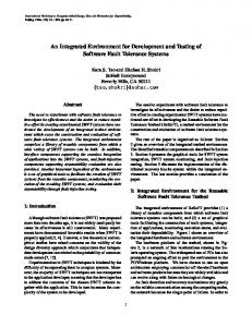
Figure 1 shows the model evolution of a Company class with an address attribute and some further attributes. The modified model has a new Address class with a new street attribute, city attribute and zip attribute. The address attribute is removed from the Company class. Furthermore there exists an association between the Company class and the Address class. This way the schema migration is uniquely defined. However the data migration is more complicated and depends on the semantics of the changes. In the current example new objects of Address type have to be created and linked to the correct Company objects, whereas their attributes have to be computed properly from the old address attributes. In a working framework solution the developer must have the capability to define the data migration based on his or her semantic knowledge about the information base. However, at the same time the developer should be supported with respect to canonically given parts of data migration, which can be generated. In our simple example the framework can assume that the remaining attributes of the Company class, i.e. the non-address attributes, are intended to have the same semantics in the new model as in the old model. Based on this assumption the data migration is conceptually just a copying for these attributes. Of course an elaborated approach has to provide a means to override the default behavior of such simple data migration parts, too.
3 3.1
The Proposed Integrated Approach The Solution Framework
In our approach applications are developed by simultaneous roundtrip engineering of Java programs and UML diagrams. The approach provides transparent
4
B. Bordbar, D. Draheim, M. Horn, I. Schulz, and G. Weber
Company address:String ···
model evolution Company ···
aCompany aCompany address: “207 Lake Bvd, ··· Minneapolis, MN 55455-0436“ database ··· reorganisation
aCompany address: “205 Hill Street, Boulder, CO 80309-0178“ ···
aCompany ···
Address street:String city:String zip:String
anAddress street: “207 Lake Bvd“ city: “Minneapolis“ zip: “MN 55455-0436“
anAddress street: “205 Hill Street“ city: “Boulder“ zip: “CO 80309-0178“
Fig. 1. Non-trivial data migration.
database access to a relational database and support for data migration. Figure 2 shows the components of the approach and their interplay. The solution consists of the following new components, which we have implemented in the IMIS project – see Sect. 4.1 – and which encompass a total of 90 kLOC of documented Java code: – Extensions to the case tool Together: • Modules for model annotations. The new model annotations allow for specifying the persistent classes of the model and the typical customizations needed for object-relational mapping [28]. • Model generator. The so-called model generator creates a model representation of the annotated UML model that is appropriate as input for the generic database adaptor and upgrader generator, which are explained below. In our implementation model representations consists of serialized Java objects. These are stored in files named model.dat in Fig. 2. – Generic database adaptor. For each concrete model this generic component [14] realizes the transparent database access layer for the application. It exploits the information in the model representation by inspection and generates the necessary SQL queries. – Arbitrary SQL query API. Note that our approach offers full-fledge support of typical mapping tools, i.e., the developer is able to formulate arbitrary SQL queries to the database that go beyond the canonically generated access methods. Our approach offers an API for this purpose. – Upgrader generator. The upgrader generator takes an old model representation, a new model representation, and an auxiliary property file. It generates an upgrader program API. Next we explain, how database reorganization is supported with the upgrader generator mechanism.
Model-Based Data Migration
5
If database reorganization becomes necessary, three steps are undertaken in our approach: (i) database cloning, (ii) schema evolution, and (iii) data migration. Please consider the middle tier of Fig. 2: (i) Database cloning. First a complete copy of the old database is done. This clone has to be adopted by schema evolution and data migration to fit the new model. (ii) Schema evolution. Then the schema of the clone is changed so that it fits to new model with respect to object-relational mapping. For this purpose the upgrader generator compares the new model with the old model and detects changes. This means that the upgrader generator constructs a schema morphism along the lines of a defined set of rules. For example classes with same name are identified in both models. Based on that, the upgrader generator can detect, for example, new attributes of a class. Of course, entirely new classes can be detected as well as deleted classes. Sometimes the default mechanism must be customized. This can be done by the developer via property files, where he or she partly defines an own schema morphism that overrides the default morphism. For example, the developer can define the renaming of a class or attribute. From the detected and defined changes the upgrader generator generates SQL code that can modify the database appropriately. (iii) Data migration. Finally, the data of the old database has to be migrated to the new database. Now cloning the database earlier pays off. For all classes that are not affected by the model evolution step data migration is already completed. For each of the other classes the upgrader generator creates an update class. All the generated upgrade classes form the upgrader API mentioned above. For some of the affected classes the upgrader generator cannot generate the correct default data creation – here the property file mechanism comes into play again: the developer can, for example, specify the movement of classes in the class hierarchy, or the movement of an attribute from one class to another. The generated data migration code reads necessary data in the old database via the old database adaptor. It sends data for the new database via RMI5 to an inserter component that writes the data via the new database adaptor into the new database. The developer can override all generated default data migration code. In cases, where the upgrader generator cannot guess a solution, data migration code must be implemented by the developer. Consider our example in Sect. 2: the upgrade API does not possess default behavior for the creation of new Address objects – the Address class is entirely new and the splitting of the old address attribute into the new attributes street, city, and zip is not trivial and must be provided by the developer. Our approach targets two objectives with respect to database reorganization: (i) development speed and robustness and (ii) technical speed: (i) Development Speed and Robustness. A major part of canonically given data migration is generated automatically. The developers have to customize only those parts, for which there semantic knowledge is required. This speeds 5
The chosen RMI mechanism is a technical detail that prevents name conflicts by employing two different JVMs for the old and the new system.
6
B. Bordbar, D. Draheim, M. Horn, I. Schulz, and G. Weber
model
Together + extra annotation modules + model-generator new application model.dat
application layer
database adaptor
database adaptor new system
cloning
property files
SQL for schema modification
inserter
upgrader generator
RMI
upgrader
upgrader API data migration old system
database adaptor
model.dat
old database
Fig. 2. The proposed integrated approach. Developer activity is denoted by a little icon. Developers work with a simultaneous round trip engineering tool. If database reorganization becomes necessary they are supported by the upgrader generator that compares the new model and the old model, detects changes and generates a data migration program with customizable hooks – the upgrader API. The developer can influence the upgrader generator with property files.
Model-Based Data Migration
7
up the development needed and therefore stabilizes the database reorganization process. Furthermore, the customizations are done on the level of transparent database access, i.e., on the application programming level, and the developers don’t have to be aware of the details of the underlying object-relational mapping all the time during data migration customization. (ii) Technical Speed. The first step in the database reorganization process is the schema migration and there would several ways to do it. One way would be the creation of a new and empty schema. This could be done easily by generating DDL statements from the object model. But creating an empty schema implies that a lot of unchanged data has to be moved from the old to the new schema. The more efficient way is to keep the data in the original schema. The schema is to be modified step by step until the structure fits the new model requirements by dropping, adding and modifying tables or columns etc. Only tables with relations to model changes are touched. However, modifying the existing data has also its pitfalls. Some object transformation processes may need information of other objects and these objects may be subject to change, too. With a copy it is not necessary to take dependencies into account, because every information is still accessible in the old schema. The most efficient and easiest way is to duplicate the database – our tests have shown that it is at least twenty times faster as an SQL based transport solution. In the past, all constraints and indices were deactivated during evolution. This step was necessary in order to avoid that the evolution process is infringed while it is processing the objects class by class. Since most of the tables and therewith most of the constraints and indices are not involved in the evolution process, a more sophisticated treatment of constraints and indices was developed. This way, in the future it will be possible to deactivate only the few constraints that really interfere with the upgrade process.
domain data
database dumps
original dump
integration of model changes into baseline
current baseline evolution
developer workspace setup
development database schemas
application data
current baseline evolution
evolution A
IMIS
current baseline dump
original dump
evolution B
imp
A B C
Fig. 3. Development process.
8
3.2
B. Bordbar, D. Draheim, M. Horn, I. Schulz, and G. Weber
The Development Process
At regular intervals, in particular after each installation, the database is dumped from the productive system for all used schemas – consider Fig. 3. The dumps are used as a basis for database schema setup during development. During development the same evolution mechanism is used that is used for installing a new software version on the productive system. Upgrader code always has to be integrated into the project workspace together with the appropriate model and code changes. This way, the consistency of model, application code and evolution code is enforced. To allow faster setup times, the number of data records is reduced in the dumps that are used during development. During integration of model changes into the project workspace the commonly used database schema is setup with the new upgrader. During setup of a developer workspace the schema is not affected. In order to prevent that the work of other developers is interfered during setup of a new schema, a second database instance is used for the new schema. Developers can decide on there own when to switch to the new schema. The developer schemas (developers A and B) are set up using the evolution that corresponds to the model changes the developer has done so far. If no model changes have been done by a developer (developer C) a dump of repository data that has already passed through the evolution in the current project workspace is used for developer workspace setup. This way, most of the developers can setup there workspace by importing a database dump. As soon as a developer integrates a model change of the repository data model into the project workspace the current workspace dump is updated using the evolution code just integrated. At customer site two systems are installed – see Fig. 4. The productive system is accompanied by a so called reference system which is used for testing purposes. The evolution process is used in two cases: (i) installation of a new release for testing onto the reference system; and (ii) installation of a new release onto the productive system. In addition to the target database, the evolution process always uses a second database as source for the upgrader.
test system installation
evolution
productive data base
test data base copy
productive installation
evolution
Fig. 4. Installation at the customer site
Model-Based Data Migration
3.3
9
On the Integrated Approach and Model Driven Architecture
IMIS draws on the vision promoted by the MDA [30]. In the MDA, the platform independent model (PIM), which is a high-level abstraction independent of any technology and platform specific model (PSM), which is the transformation of the PIM into a specific platform. In our approach, the PIM is captured as a UML model in Together CASE tool, which is transferred by the model generator component to a model.dat file, which is just another way of representing the PIM. This file is transformed into code consisting of Java, SQL DDL and eventually SQL DML. Our approach is based on marking PIMs and direct transformation to code – see Sects. 3.5. and 3.7 of the MDA Guide [21]. However, it is noticeable that the transformation in our approach takes a special shape. Simultaneous roundtrip engineering keeps the model and the code in synch by continuous tool support. Furthermore, the transformation explicitly makes use of an old PIM (and for technical speed even of an old implementation), because there are parts in the generated code, i.e., schema manipulating SQL code and customized Java data migration code, that depends on a notion of PIM model difference. As a result, the transformation takes into account the information layer, i.e., existing data, on a conceptual level. There are different forms of model transformation in the MDA [8, 16]. Round trip engineering points out an important class of transformations, too. There are two main advantages in using this kind of transformations. Firstly, code may include platform specific information added by the developer. In particular, it may include part of the code that cannot be created automatically. A rigid following of an ad-hoc MDA scenario would imply that either we have to discard such information, i.e., we (i) have to re-include them into the code generated from the new model – which is wasteful and error-prone – or (ii) we have to reverse engineer [5] the entire code to create a system which mirrors the old system – which is impractical and can create possible inconsistencies. In our approach, it is particularly important that the new and the old system share persistent data. The model goes through evolution, but the persistent data is cloned and adopted under the umbrella of a defined model transformation. A conventional MDA model transformation remains far from data, even if it transfers the DB schema across. There is no defined coupling between the persistent data and the evolution from the old model to the new one.
4 4.1
Experiences with the Integrated Approach The IMIS System
Following the nuclear accident in Chernobyl the German federal government established a program targeting radiation protection and precaution in 1986. By the end of 1986 the respective federal law StrVG (Strahlenschutz Vorsorge Gesetz) was adopted. Besides other rules the StrVG contains guidelines for the
10
B. Bordbar, D. Draheim, M. Horn, I. Schulz, and G. Weber
installation of an information system for monitoring and prediction of radioactivity in the environment. The first version of IMIS was developed between 1989 and 1993 and it has been in use till March 2005. In this paper we describe the entirely new IMIS system, which has been developed by Condat AG in Berlin, Germany. IMIS gathers environmental data, for example, from air, sea, lakes, ground water, plants, soil, food, feed, sewage, waste. IMIS has the following characteristics: – – – –
2000 measurement stations; more than 160 deployed clients; 60 client locations; 7 days and 24 hours operation.
From the end user’s viewpoint the IMIS system has to be understood as a collection of rather loosely coupled client applications that together provide a broad range of features: data collection (automatic and manual), data export, data import (in particular from the forecast system PARK), data analysis (browsing with different views, domain specific visualization capabilities), document generation (automatic and manual), document retrieval. The IMIS Data. The IMIS database consists of four schemas, i.e. IMIS, a repository schema, IMISGEO and PARK. The schema IMIS consists of approximately 150 tables and basically contains the radioactivity data, master data with references to radioactivity data and data about samples. A sample is a portion of material that has been collected for radiological measurements. A sample is described by various attributes, e.g. the kind of collected material. The location from where a sample has been taken can be specified by coordinates or by an administrative district. Each sample is used for a number of measurements using various methods, e.g. alpha spectrometry. A measurement result consists of a number of readings, e.g. nuclides U-234 or U-235. The repository schema consists of approximately 300 tables and contains configuration and setting data as well as dynamic data not related directly to radioactivity data. The configuration data is used to customize the various functions of IMIS, e.g. the selection and representation component. For instance, stored messages or journals of automatic processes belong to the dynamic data stored in the repository schema. The schema IMISGEO contains geographical data, e.g. maps for spatial evaluations. This schema is not covered by the evolution mechanism described in this paper. The schema PARK contains prognosis data computed by the external forecast system PARK. The PARK subsystem is only used in emergency mode. PARK prognosis data has a comparatively short lifetime, therefore data migration is not necessary for this schema. It can be emptied prior to schema evolution. System Architecture and Configuration. The system architecture of the IMIS system is depicted in Figure 5. A central Oracle9i database stores the data for evaluation and further processing. Configuration data for the different functions of IMIS is stored in the same database instance. It is running on a Sun V880 high availability cluster server consisting of two nodes. For data storage two Sun T3 storage subsystems are used. Server and communication processes are hosted
Model-Based Data Migration
11
measurement stations
client tier
server application logic
document management system
PARK system
FTP server
PARK controller
job batch processing
application server cluster
database cluster
Fig. 5. The IMIS Integrated Measurement and Information System.
on four Sun Fire 280 application servers. They are redundant and can replace each other in case of failure. All servers are located at the German federal office for radiation protection BfS (Bundesamt f¨ ur Strahlenschutz) in Munich. PCs are used as client systems. The client software follows a straightforward fat client approach. While most of the clients are connected via ISDN to the server LAN, the clients located on site in Munich are connected directly via Ethernet. Most of the new data that is stored into the IMIS database stems from the measurement stations. These provide data by uploading it to an ftp server. From there the data is written by bulk data transfers, in normal operation mode on a daily basis and on a two hour basis in emergency operation mode. Further data is stored into the database by the external PARK system through the PARK controller. Further few data is entered manually by the user. Up to exceptions all the data stored in the IMIS system is long-lived, almost all the data stays unchanged. There is no heavy transaction load on the IMIS system. IMIS is estimated to store data about approximately one million measurements per year - this is equivalent to several million records. This leads to a forecast of approximately 50 GB measurement data after 10 years – if certain data transforms become necessary due to changing requirements, e.g. for reasons of analytical processing, the actual needed database size has to be reestimated. 4.2
Usage of the Integrated Approach in the IMIS Project
The new IMIS has been installed in a preliminary version in October 2003 and was used for continuous test operation until November 2004. At this point in time the system was upgraded to the final version using the upgrade technique described here for the first time in an productive environment. In February 2005
12
B. Bordbar, D. Draheim, M. Horn, I. Schulz, and G. Weber
an improved and optimized update was installed, which officially substituted the old IMIS system on April 1st 2005. The data stock has continuously evolved during the test period from October 2003 till February 2005 and was migrated to each new version with the evolution technique described here. Figure 6 shows some key figures for both major evolution steps. For each installation the total number of data records in the database, the number of model changes and the quantity of objects that were actually affected by data migration are given.
total number of data records IMIS repository
11-22-04
02-26-05
14.1M 6.0M
20.8M 8.5M
20.1M
29.3M
152 280
152 279
28 69
9 23
32 87
5 33
~ 4700
~ 3600
~ 270
~ 1300
number of tables IMIS repository
134 278
model changes (oo) classes created/deleted attributes/associations created/deleted model changes (relational) tables created/deleted columns created/deleted/modified data modifications objects updated/inserted associations updated/inserted
Fig. 6. Results of IMIS tool support for data migration.
Besides these figures we gained the following experiences: – The actual evolution step, which is copying objects between the old and the new database, takes only three to five minutes on our target hardware. Therefore the mechanisms that has been implemented to reduce the necessity of object copying can be considered as working. – The usage of evolution code during development leads to a reliable data migration at customer site. We encountered no data corruption or misses caused by evolution. – Both uses of the evolution technique performed on the real system has shown that auxiliary steps that accompany the actual evolution are much more time consuming. • Dump importing was rather costly and took up to three hours. Currently we change the database cloning step to use the data backup and restore routines of the Oracle recovery manager to copy the old content between the databases.
Model-Based Data Migration
13
– Most of the model changes are more or less trivial like attribute insertion or deletion. Changes that require one of the more sophisticated evolution techniques offered by our framework are rather seldom. – However, the offered sophisticated techniques are particularly useful for complex model changes. For example, during the last installation a new table was created that normalizes a set of three columns that were contained in two other tables before. The new table was filled and the attribute columns were replaced by foreign keys.
5
Related Work
ORION [15, 4] is an object-oriented database. It provides a solution to data migration based on dynamic schema evolution that targets the physical level. It is possible to change the schema in a deployed instance of the ORION database. The ORION data migration mechanism is adaptional. This means, that data and application code is adopted to a new model in the evolution cycle. The TSE [25] solution never deletes parts of the defining model. Schema versioning is based on a view mechanism and all changes, i.e., in particular deletes, are recorded in view changes. Schema versioning [27] is combined with an adaptional mechanism in the O2 [12] system. O2 minimizes needed application reconstructions. OTGen [18] is based on a generator for data migration programs. Input to the generator is a declarative definition of an object-relational mapping. The successor of OTGen is the Tess [17] system. The Tess generator also takes into account an existing old schema so that it can generate an initial schema mapping itself. Clio [23, 22] is an exemplary system for automatic schema matching [26], which is supported by a correspondence engine. The mapping generator of Clio gets source and target schemas as input. The analysis in [20] clarifies the relationship between data migration and model evolution, given a scenario with a relational schema and a semantic data model. The approach in [3] succeeds in representing relational views in OCL, whereas [19] discusses extensions to UML for database design taking into account the object-relational features of modern database technology. [2] proves that the UML has the expressive power of the relational algebra and it is possible to use OCL as a query language. The approach in [24] shows that it is possible to specify consistencies for legacy data sources in OCL.
6
Conclusion
A round-trip engineering can play the role of an integrated development environment. If cohesion in work product management is the goal [11] support for object-relational mapping should be integrated into each CASE tool that is used in a typical multi-tier setting. Providing a transparent database access layer clearly falls into the area of generative programming and has to deal with the intrinsic questions of this domain like generator type safety [10]. Improving
14
B. Bordbar, D. Draheim, M. Horn, I. Schulz, and G. Weber
schema evolution and data migration with respect to an object-relational mapping has subtle issues, because object-relational mapping is a practical challenge on its own. If an MDA tool does not support data migration it stops supporting the developer of a data-centric application adequately after the first version of the system has been deployed at the customer site.
References 1. 2. David H. Akehurst and B. Bordbar. On querying UML data models with OCL. In Martin Gogolla and Cris Kobryn, editors, UML 2001 - The Unified Modeling Language. Modeling Languages, Concepts, and Tools. 4th International Conference, Toronto, Canada, October 2001, Proceedings, volume 2185 of LNCS, pages 91–103. Springer, 2001. 3. Herman Balsters. Modelling Database Views with Derived Classes in the UML/OCL-Framework. In UML, pages 295–309, 2003. 4. Jay Banerjee, Won Kim, Hyoung-Joo Kim, and Henry F. Korth. Semantics and Implementation of Schema Evolution in Object-Oriented Databases. ACM SIGMOD Record, 15(4), February 1987. 5. Elliot J. Chikofsky and James H. Cross. Reverse Engineering and Design Recovery: A Taxonomy. IEEE Software, pages 13–17, January 1990. 6. Don Coleman, Dan Ash, Bruce Lowther, and Paul Oman. Using Metrics to Evaluate Software System Maintainability. IEEE Computer, 27(8):44–49, August 1994. 7. Graham Colleen. DBMS Software Market: Flat but Not Calm, Dataquest Alert. Gartner Group, May 2002. 8. Krzysztof Czarnecki and Simon Helsen. Classification of Model Transformation Approaches. In 2nd OOPSLA Workshop on Generative Techniques in the context of Model Driven Architecture, 2003. 9. Dirk Draheim, Matthias Horn, and Ina Schulz. The Schema Evolution and Data Migration Framework of the Environmental Mass Database IMIS. In Proceedings of SSDBM 2004 - 16th International Conference on Scientific and Statistical Database Management. IEEE Press, 2004. 10. Dirk Draheim, Christof Lutteroth, and Gerald Weber. Generative Programming for C#. ACM SIGPLAN Notices, to appear. 11. Dirk Draheim and Gerald Weber. Form-Oriented Analysis - A New Methodology to Model Form-Based Applications. Springer, October 2004. 12. Fabrizio Ferrandina and Sven-Eric Lautermann. An Integrated Approach to Schema Evolution for Object Databases. In 3rd International Conference on Object-Oriented Information Systems, pages 280–294. Springer, December 1996. 13. Linda Heaton. Meta Object Facility (MOF) Specification 1.4. Technical Report formal/02-04-03, Object Managment Group, 2003. 14. M. Horn, V. Triestram, and J. van Nouhuys. Data Evaluation Using the Generic Selection Component of the New IMIS System. In EnviroInfo 2003 - 17th International Conference Informatics for Environmental Protection. Metropolis, 2003. 15. J.Banerjee, H. Chou, J.Garza, W.Kim, D.Woelk, and N.Ballou. Data Model Issues for Object-Oriented Applications. ACM Transactions on Information Systems, 5(1), January 1987.
Model-Based Data Migration
15
16. I. Kurtev and K. van den Berg. Unifying Approach for Model Transformations in the MOF Metamodeling Architecture. In 1st European MDA Workshop. University of Twente, March 2004. 17. Barbara Staudt Lerner. A Model for Compound Type Changes Encountered in Schema Evolution. ACM Transactions on Database Systems, 25(1):83–127, 2000. 18. Barbara Staudt Lerner and A. Nico Habermann. Beyond Schema Evolution to Database Reorganization. SIGPLAN Notices, 25(10):67–76, 1990. 19. Esperanza Marcos, Bel´en Vela, and Jos´e Mar´ıa Cavero. Extending uml for objectrelational database design. In UML, pages 225–239, 2001. 20. Victor M. Markowitz and Johann A. Makowsky. Incremental Reorganization of Relational Databases. In 13th International Conference on Very Large Data Bases, pages 127–135. Morgan Kaufmann, 1987. 21. J. Miller and J. Mukerji. MDA Guide Version 1.0.1. Technical Report omg/200306-01, Object Managment Group, 2003. 22. R. J. Miller, L. M. Haas, and M. Hernandez. Schema Mapping as Query Discovery. In Proceedings of the International Conference on Very Large Data Bases, pages 77–88. Morgan Kaufmann, 2000. 23. Ren´ee J. Miller, Mauricio A. Hern´ andez, Laura M. Haas, Lingling Yan, C. T. Howard Ho, Ronald Fagin, and Lucian Popa. The Clio Project: Managing Heterogeneity. SIGMOD Record (ACM Special Interest Group on Management of Data), 30(1):78–83, 2001. 24. Jan Pettersen Nytun and Christian S. Jensen. Modeling and Testing Legacy Data Consistency Requirements. In UML, pages 341–355, 2003. 25. Young-Gook Ra and Elke A. Rundensteiner. A Transparent Object-Oriented Schema Change Approach Using View Evolution. In 11th IEEE International Conference on Data Engineering. IEEE Press, 1995. 26. Erhard Rahm and Philip A. Bernstein. A Survey of Approaches to Automatic Schema Matching. VLDB Journal: Very Large Data Bases, 10:334–350, 2001. 27. J. Roddick. A Survey of Schema Versioning Issues for Database Systems. Information and Software Technology, 37(7):383–393, 1995. 28. Devang Shah and Sandra Slaughter. Transforming uml class diagrams into relational data models. pages 217–236, 2003. 29. Gary H. Sockut and Robert P. Goldberg. Database Reorganization - Principles and Practice. ACM Computing Surveys, 11(4):371–395, 1979. 30. Richard Soley. Model Driven Archtitecture, white paper formal/02-04-03, draft 3.2. Object Managment Group, November 2003. 31. Ruth Sterto. White Paper: Persistent Data Development Tools Validate the Model Driven Architecture Approach. Technical report, Progress Software Corporation, 2004. 32. Can T¨ urker. Schema Evolution in SQL-99 and Commercial (Object-)Relational DBMS. In 9th International Workshop on Foundations of Models and Languages for Data and Objects - Database Schema Evolution and Meta-Modeling, volume 2065 of LNCS. Springer, 2000. 33. Edmond VanDoren. Maintenance of Operational Systems - An Overview. In Software technology Roadmap. Carnegie Mellon Software Engineering Institute, 1997.