Chapter II briefly describes the hardware configuration of the PSR platforms. ... activated, behavioral parameters, and error recovery logics. The Petri net based ...
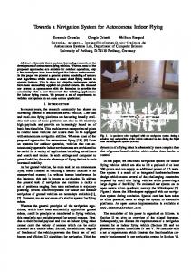
Integrated Navigation System for Indoor Service Robots in Large-scale Environments Woojin Chung, Gunhee Kim, Munsang Kim, Chongwon Lee Intelligent Robotics Research Center Korea Institute of Science and Technology 39-1 Hawolgok-dong, Sungbuk-ku, Seoul, 136-791, Korea { wjchung, knir38, munsang, cwlee }@kist.re.kr Abstract - This paper describes an integrated navigation strategy for the autonomous service robot in large-scale indoor environments. It includes architecture of navigation system, the development of crucial navigation algorithms like map, path planning, and localization, and planning scheme such as error/fault handling. Major advantages of proposed navigation are as follows: 1) A range sensor based generalized scheme of navigation without modification of the environment. 2) Intelligent navigation-related components. 3) Framework supporting the selection of multiple behaviors and error/fault handling schemes. A experimental result shows the feasibility of proposed navigation system. The result of this research has been successfully applied to our three service robots in a variety of task domains including a delivery, a patrol, a guide, and a floor cleaning task. Index Terms - Service robot, navigation, localization, path planning, Petri nets
3) It is desirable that the navigation system takes both global and local approaches. It is inefficient to run navigation algorithms using the detailed information about whole workspaces like a building and a hospital. Rather, the robot had better interpret only its local information in detail and use global information roughly. 4) The algorithms used in our navigation system should be generally applicable. A unified approach is advantageous from the viewpoint of system integration and dependability of a system. For example, we prefer to implement the path planner by using only one algorithm. If a fixed reference path planning and a dynamic obstacle avoidance problem are solved separately, it results in difficult tunning and integration problem in practice. Also, it is not advisable put together several solutions handling case-by-case problems like moving in a passage, passing through the door, and so on.
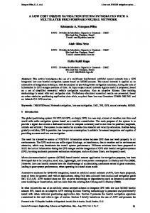
I. INTRODUCTION In recent years, there have been various trials to extend robotics technology to non-industrial applications, such as surgery, rehabilitation, floor cleaning, and so forth. At the KIST (Korea Institute of Science and Technology), intelligent multi-functional robots are under development toward public services in large-scale indoor environments. So far, we have built three versions of the PSR (Public Service Robot) systems, PSR-1, PSR-2, and a guide robot Jinny, as shown in Fig.1. Also, we implemented four target service tasks, a delivery, a patrol, a guide and a floor cleaning task. Autonomous navigation is one of the most challenging issues for the development of indoor service robots. We summarized following requirements for our navigation system. 1) The robot should navigate in a crowed environment without any artificial landmarks. This requirement results in many difficulties such as the localization problem and safety issues. 2) The navigation system should efficiently cope with various situations which are resulted from the uncertainty of environments. For example, if the robot is surrounded by people, it may lose its way or fail to find out the path to the desired location. Therefore, it is required to define efficient framework in order to manage these various situations that frequently occur in a real environment.
(a) PSR-1
(b) PSR-2 Fig. 1 Three PSR systems.
(c) Jinny
A major scope of this paper is to propose the integrated navigation system applicable in real environments as a complete solution. It includes hardware integration for sensors and actuators, the development of crucial navigation algorithms like maps, path planners, and localizers, and planning scheme such as error/fault handling. Experimental results will be presented in order to show the feasibility of proposed navigation system. So far, there have been many related research activities about a navigation strategy in a dynamic environment. Some remarkable systems have been developed like MINERVA [1], CLARAty [2], and RoboX [3]. However, it is still difficult to apply these schemes in our case directly. They do not fully solve our requirements. Our navigation system has following two contributions over previous navigation systems. First, each developed module has its own intelligence. It means each component has
not only its own function but also the ability to analyze internal states and environmental information. They are reported in forms of events, and used for smart behaviors of a robot. Second, the proposed navigation system provides framework which supports the selection of multiple behaviors and the error/fault handling schemes. Chapter II briefly describes the hardware configuration of the PSR platforms. Chapter III illustrates an overview of the developed navigation system first, and then explains some key navigation modules. The results of experiments are discussed in Section IV. Finally, some concluding remarks are given in Chapter V. II. HARDWARE CONFIGURATION OF THE PSR SYSTEMS The PSR systems have several types of sensors for autonomous navigation. Our approach is based on the rangesensors. Two laser range finders are set up on front and rear sides, and two infrared scanners are equipped on left and right sides in order to cover all peripheries of the robot. The PSR-1 and PSR-2 have holonomic omni-directional movements while the Jinny has a two wheel differential mobile base. Omni-directional movement provides practical advantages for the PSR-1 and PSR-2 since they should carry out not only autonomous navigation but also mobile manipulation and control of multiple passive trailers. III. INTEGRATED NAVIGATION SYSTEM A. Overview of integrated navigation system
Fig. 2 Overview of Integrated navigation system.
Fig. 2 shows the structure of our integrated navigation system, which is classified into three parts, a low-level planning part, an information part, and a reactive part. It is designed considering significant architectural issues, which includes information connectivity between a variety of modules, scheduling of information processing, combination of reactivity and deliberation. The detailed description of whole control architecture of PSR system is introduced in [4]. The Navigation modules are the information part that extracts perceptually meaningful information from raw sensor data using a various kinds of sophisticated time-consuming
algorithms. The main components are maps, localizers, and path planners. The reactive layer controls the robot motion by executing relatively simple computation in real-time. The resources provide framework for efficient fusion of different kinds of sensor data. The behavior, which is a basic motion generator, tightly coupled with sensors and actuators. The behavior coordinator fuses the control command from one or more behaviors, and the controller drives the actuators. The low-level planning part consists of the process supervisor and the low-level configuration. By referring to low-level configuration, the process supervisor executes an internal process, which is a subtask in our architecture, transmitted from the central planner. The low-level configuration encapsulates whole information about the execution of a given process such as lists of behaviors to be activated, behavioral parameters, and error recovery logics. The Petri net based approach is adopted for the design of the low-level configuration [4]. The advantage of Petri net based approach will be exampled in the section F. In order to explain the overall strategy of our navigation system, a simple delivery task is considered. If a user gives a command to deliver the target object to a far-off room, the global path planner initially generates a node path set based on a topological map. Each node point becomes the goal position of a navigation process PrAutoMove. By iterating these processes, the robot can reach desired position regardless of how far it is located. If the robot senses that the planned path is obstructed during navigation, then the topological map is updated and the global path planning is performed again. The following sections focus on the explanation of five key components, maps, localizers, path planners, tracking behaviors, and configuration design. B. Maps The map is important both to a user and to a robot. Our navigation system possesses four different types of maps. For a user, an information map is defined. For a robot itself, topological maps, local grid maps, and active maps are used. The information map displays user-friendly environmental information to be used in the human interface display. For example, a user can know where the room 3211 or a rest room is located through the information map. It helps a user both to command and to monitor the system. The topological map compactly describes the entire environments with nodes and arcs. It is used for global path planning. The topological map contains two types of important information. First, it assigns physical locations which are meaningful to a user as nodes. For example, it includes the site of an exhibit, the position of a mailbox, and so forth. Thus, it is used as the goal position of process PrAutoMove. Second, the topological map describes connectivity between the local grid maps. In our system, the whole workspace is represented by several patches of detailed local grid maps due to memory limitation and computational inefficiency. The robot loads an appropriate local map according to its current position. By using both a topological
and a local grid map in the proposed way, advantages of both approaches can be fully exploited. The local grid map contains the accurate information of the surroundings of a robot. It is used for time-consuming localization algorithm. The local grid map is not changed in run-time. Since the implemented localization algorithm is performed by map-matching technique, computing time is closely connected to a map size. Therefore, the local grid map should be set moderately. It represents environments by evenly-spaced grid cells. The resolution is 10 cm. The grid value is assigned to each cell for representing the characteristics of environments such as the presence of obstacles and the state of a floor. The grid map can be generated by using the range image registration technique, one of autonomous off-line map building algorithm [5]. This technique is convenient since the local map is automatically constructed by just arbitrarily moving the robot through the environment. The active map is defined for local path planning. It has similar structure with the local grid map since it is created by loading a part of the local grid map. After the loading, the active map is updated in run-time by using different kinds of sensor data independently. The Histogramic In-Motion Mapping (HIMM) [7] is applied for real-time map updating. The updating rate depends on the sampling time of each sensor. For example, a laser scanner updates the active map every 100 msec. This updating rate is fast enough to apply in real dynamic environments. The active map is created when a navigation process PrAutoMove is started, and destroyed when it terminates. Since the active map is set with a 10m × 10m size, two adjacent node points should be located on this area. C. Localizer Our localization method is a probabilistic map-matching scheme based on Monte Carlo localization [8]. Thus, our localizer is applicable in a dynamic environment without any artificial landmarks. It can use any kinds of range sensors, and handle both local tracking and global position estimation. Two measure functions, Range Image Similarity Measure Function (RISF) and Angular Similarity Measure Function (ASF), are developed for computing positional probabilities. The details of the reliable position estimation method of the PSR are introduced in [5] [6]. The advantages of the proposed localization scheme as follows. 1) The scheme is applicable in both polygonal and nonpolygonal environments. ASF provides fast sample convergence and high accuracy in polygonal environments. RISF makes it possible to estimate the position in nonpolygonal surroundings. 2) Our smart localization considers not only position estimation but also exception handling. It helps a robot take appropriate action like human beings by introducing discrete event control concept.
D. Path planner Our system has both global and local path planners. The global path planner generates an optimum node path set on a topological map. The local path planner generates the shortest collision-free path between these node points. Our path planning algorithm is developed by modifying Konolige’s gradient method [9]. We mainly explain the local path planner in this paper, since the global path planner is a simple extension of a local one. Fig. 3 shows our local path planning algorithms. The local path planner repeats this algorithm until the robot reaches the desired position. Step 1: Gathering all necessary input data (1) Obtaining the current position of a robot (2) Setting target node point as a goal set. (3) Generating an obstacle set from the active map. Step 2: Building the navigation function. (1) Calculating intrinsic cost. (2) Calculating adjacency cost. Step 3: Checking error states (1) Checking whether the original goal is restored. (only if the original goal has been changed.) (2) Checking whether the goal is occupied. (3) Checking whether no path to the goal exists. Step 4: Generating path set (only if one or more of path updating rules are satisfied.) (1) Constructing a path set by steepest descent method. (2) Smoothing the path using Bezier interpolation. (3) Performing velocity planning. Fig. 3 Local path planning algorithm.
The first step is to gather all input data required to execute the local path planning. They include the position of a robot, a goal set, and an obstacle set. In most cases, the goal set has one element, which is the coordinates of a target node point of the PrAutoMove process. The obstacle set is obtained by interpreting the active map. Obstacle regions in the active map are enlarged as much as robot radius since the path planning algorithm assumes a robot to be a point. The second step is the generation of the navigation function. The detailed explanation of the navigation function is given in [9] and [10]. The third step is to check whether the path planner falls into error states. Our algorithm deals with two exceptional cases, path blocking and goal occupation. Such situations happen very often in a human co-existing environment. The occurrence of these errors can be automatically detected by checking the navigation function. The path blocking implies that there is no path between two adjacent nodes. If the path blocking arises, the robot stops
moving and waits until a new collision-free path is detected. If the path is still obstructed after a pre-determined time, the local path planner gives up continuing the PrAutoMove Process. It is reported to the central planner and causes the update of the topological map. Then, the global path planner regenerates the path node set. The goal occupation by an obstacle is resolved by setting a temporary intermediate goal. Then, the path planner checks continuously removal of the obstacle on the original goal during the motion. When the robot reaches the temporary goal and stays at this point for a long time, it gives up reaching the original goal. It leads the central planner to generate a new process PrAutoMove that has another goal position. The last step is to generate a path set based on the navigation function. The optimal path without local minima is computed by moving in the direction of the gradient of the navigation function. The planned path is represented by an ordered set of points on the active map. The path set is not updated every time since frequent changes of reference paths cause the instability of tracking control. Thus, detailed generating process is executed only if one or more of following path updating rules is satisfied. 1) Initial computation of a path set: It means that any path set has not been constructed for the current navigation process. 2) The change of the goal position: This occasion arises if a temporary goal is set by an obstacle occupation or the original goal is restored by removal of an obstacle. 3) The detection of an obstacle on some points of the existing path set: If the existing path is obstructed partially by a newly sensed obstacle, the path set is updated. 4) The large amount of decrease of the number of intermediate points in an existing path set: It implies that the path planner discovers a new path shorter than the old one. The optimal path is obtained by applying steepest descent method to the navigation function. The smoothing process follows so as to improve tracking performance. The Bezier interpolation is adopted in our algorithm. It makes it possible to smooth the path without loss of geometric continuity in a relatively simple manner. The resultant path set also contains the information about robot velocities. The distance between two adjacent points in the path set is proportional to the robot’s speed. On a main computer of PSR, a 1.2 GHz Pentium processor PC, it takes about 0.6 second on average to execute the whole path planning algorithm shown in Fig. 3. The generation of the navigation function, the step 2 of the algorithm, dominates the computation time. Note that the computing times are measured while the PSR performs an actual service task. It means that this result is obtained while the PSR activates every component including several timeconsuming algorithms such as localization. We can conclude that the computing time of implemented path planning algorithm is acceptable in actual environment.
E. Tracking Behavior The behavior generates a robot motion by tracking the path set given from the local path planner. The behavior follows the elements of the path set one by one in every sampling loop. Two types of behaviors are developed for bidirectional and holonomic omni-directional mobile base. The behavior also includes additional logics for practical implementation. For example, the behavior has an emergency stop function which uses only raw sensing data. It can be helpful to prevent the collision of a fast moving object. F. Configuration design for process PrAutoMove In our navigation system, each navigation-related module has its own intelligence. It means each component has not only its own function but also the ability to analyze internal states and environmental information. For example, the path planner generates a reference trajectory, and provides important information like a goal occupation by an object in forms of events. These events have an influence on the selection of a robot behavior. However, as the event-generating modules and the concerned events increase, it becomes troublesome to handle these situations. It is difficult to manage them with if-then logics. Therefore, we developed general framework, which is the Petri net based configuration. By using a proposed scheme, several significant issues can be solved, for example, task decomposition, error/fault detection and recovery, and handling many events received from several modules. Basically, we consider the events from the localizer, the path planner, and behaviors. The events from other modules can additionally be considered if the robot performs another special task like a floor cleaning task. Fig. 4 and Table I represent the Petri net model of the process PrAutoMove as a typical example of configuration design. If the process PrAutoMove starts, the transition t1 fires, the tokens are assigned to place P1, P2, and P10. These tokens explicitly monitor the state of a behavior, a localizer, and path planner. If an event is transmitted from one of these components, the distribution of tokens is changed. It means the robot changes its behavior and the internal state. The error and fault states are also considered. If the robot falls into an error state, the recovery process is executed. However, if the problem remains unresolved, the process supervisor posts the failure of a given process and terminates the execution. This result is reported to the planner, which reconfigures the planned sequence of processes. Petri nets are advantageous in our system, because the activities on the configuration level are event-driven and the state of a system can be divided into the possible discrete states. As a graphical tool, Petri nets can visualize the control logics in configurations and make it easy to check the states of systems. Moreover, the dynamic change of states can be explicitly described since the Petri nets exploit tokens, which clearly indicate state transition with respect to event firing. As a mathematical tool, it is possible to set up mathematical models and analyze the designed logics. Therefore, it is convenient to define an efficient error handling schemes.
execution of PrAutoMove processes, we only show the results of a single PrAutoMove process in this paper.
Fig. 4 Petri net model of process PrAutomove. TABLE I DESCRIPTION OF PLACES AND TRANSITION OF FIG.4 PL/TR P0 P1 (P6) P3 (P2)
Description Standby. Executing (Completing) the behavior BhAutoMove. State: The original goal has (NOT) been changed.
P4
Error: The path to the goal does not exist. (The robot stops moving and waits until a new path is detected.)
P5
Fault: The path to the goal does not exist.
P7 P8 P9 P10 P11 P12 t0 (t6) t1 t2 t3 t4 t5 (t13) t7 t8 t9 t10 t11 (t12)
Error: Reach the temporary goal and stop moving until the original goal is restored. Fault: Reaching the original goal is failed since it is occupied by an obstacle. Error: The behavior BhAutoMove CANNOT extract the desired point from path set. (The behavior reaches the last point in the path set.) State: Normal localization. (Localizer updates a robot position periodically.) State: Abnormal localization. (Localizer doesn’t update a robot position, and robot navigates only by using odometry.)
Fig. 5 An experimental environment.
Fig. 6 shows the results of the path planning during the navigation. The start point is (3.6 m, 3.3 m), and goal is (6.0 m, 10.5 m). It shows some active maps and planned paths. The actual trajectory, initial position of the robot, and the target node are presented in Fig. 6.(a). A user stands intentionally in the PSR’s way several times. The collision-free optimal path is changed according to the locations of obstacles. If the user walk in the middle of the passageway as represented in Fig. 6.(c), the PSR takes a roundabout way. Note that the obstacle points are enlarged by a robot radius plus a safe distance. Fig.6.(d) shows the case of goal occupation by a moving object. The temporary goal is set, and the robot stops moving until the original goal is restored.
Fault: A robot fails to find out its own position. Process supervisor (PS) starts (completes) the behavior BhAutoMove. Local Path planner (LPP) changes the original goal due to the goal occupation. LPP restores the original goal position since the obstacle is removed. LPP detects the error “no path to the goal.” LPP finds out a path to the goal. PS terminates the behavior BhAutoMove due to “No path to goal exists.” (due to “The failure of localization.”) PS reaches the changed goal and stop moving. LPP detects a new goal which can be the original goal or another temporary goal. PS terminates the behavior BhAutoMove due to the failure of reaching the original goal. The behavior BhAutoMove CANNOT extract the desired point from the path set. Localizer finds out the estimated position is (NOT) accord with the actual robot position.
(a)
(b)
IV. EXPERIMENTS AND RESULTS The developed navigation system is implemented and tested on the PSR-2 platform. Fig. 5 shows experimental environment, a conventional office room. Its size is about 10m × 35m. Since global movement is composed of consecutive
(c) (d) Fig. 6 The results of path planning during PrAutoMove.
As shown in Fig. 6.(a), the robot’s actual trajectory has the discontinuity which mainly results from position updates by the localizer. The robot can move smoothly since the behavior also contains several schemes for stable tracking such as an acceleration filter.
2) Intelligent navigation-related module: Each component has the ability to analyze internal states and environmental information, and reports them in forms of events. They help the robot behave smartly. 3) Framework supporting the selection of multiple behaviors and error/fault handling schemes: Appropriate design of the Petri net based configuration surely guarantees reliable robot’s operation. ACKNOWLEDGMENT This research is partially supported by the grant of the “Development of a service robot technology” project, Ministry of Science and Technology, Korea. The authors acknowledge Dr. Kurt Konolige at the SRI for the fruitful discussions, and Hyundai Heavy Industry Company for prototyping the PSR systems. REFERENCES
(a) Fig. 7
(b) The results of localization during PrAutoMove.
Fig. 7 shows the results of localization. It represents the local map, laser scan data, reference data, sample distributions, and estimated position each calculation. The data for Fig. 6 and Fig. 7 is gathered simultaneously with a single experiment. The reference measurements of an estimated robot location are mostly consistent with the scan measurements of an actual robot position. It means that the accurate position estimation is accomplished. Although a user disturbs the PSR’s navigation, the proposed localization algorithms work successfully. Fig. 7 shows that sensor measurements are partially corrupted due to dynamic objects. The maximum reference distance is set as 8 m to avoid open space problem as shown in Fig.7.(b). V. CONCLUSION This paper presents an integrated navigation strategy of the service robot PSR. The proposed navigation system has been applied to our three platforms in various task domains [4] [11]. A delivery and a floor cleaning task were successfully carried out by PSR-1 and PSR-2 in an office building. Also, our guide robot Jinny has been demonstrated in several exhibit hall. Major advantages of the proposed system can be summarized as follows: 1) A range sensor based generalized scheme of navigation without modification of the environment: Range sensors are implemented for map construction, path planning and localization. There is no fundamental limitation of using any type of range sensors like ultrasonic, infrared, or laser range sensors. Multiple roles of the map were successfully implemented for environmental representations, a reference database of a localization, as well as optimal path generation to the goal. Also, navigation is carried out without any artificial landmarks.
[1] Sebastian Thrun, Maren Bennewitz, Wolfram Burgard, Armin B. Cremers, Frank Dellaert, and Dieter Fox, “MINERVA: A SecondGeneration Museum Tour-Guide Robot,” in Proceeding of the IEEE Conference on Robotics and Automation, Detroit, Michigan, USA, pp. 1999-2005, 1999. [2] C.Urmson, R. Simmons, and I. Nesnas, "A Generic Framework for Robotic Navigation," in Proceedings of the IEEE Aerospace Conference, MT, pp.2463-2470, 2003. [3] K. Arras, R. Philippsen, N. Tomatis, M. Battista, M. Schilt, and R. Siegwart, “A Navigation Framework for Multiple Mobile Robots and its Application at the Expo.02 Exhibition,” in Proceeding of the IEEE Conference on Robotics and Automation, Taipei, Taiwan, pp. 1992-1999, 2003. [4] Gunhee Kim, Woojin Chung, Munsang Kim, and Chongwon Lee, “Tripodal Schematic Design of the Control Architecture for the Service Robot PSR,” in Proceeding of the IEEE Conference on Robotics and Automation, Taipei, Taiwan, pp.2792-2797, 2003. [5] Dongheui Lee, Woojin Chung, Munsang Kim, “Autonomous Map Building and Smart Localization of the Service Robot PSR,” in Proceeding of the IEEE/RSJ International Conference on Intelligent Robots and Systems, Las Vegas, Nevada, 2003. [6] Dongheui Lee, Woojin Chung, Munsang Kim, “A Reliable Position Estimation Method of the Service Robot by Map Matching,” in Proceeding of the IEEE Conference on Robotics and Automation, Taipei, Taiwan, 2003. [7] J. Borenstein and Y. Koren, “Histogramic In-Motion Mapping for Mobile Robot Obstacle Avoidance,” IEEE Trans. on Robotics and Automation, vol. 7, no. 4, Aug. 1991, pp. 535-539. [8] D. Fox, W. Burgard, F. Dellaert, and S. Thrun, “Monte Carlo Localization: Efficient Position Estimation for Mobile Robots”, in Proceeding of the National Conference on Artificial Intelligence (AAAI'99), Orlando, Florida, 1999. [9] Kurt Konolige, “A Gradient Method for Realtime Robot Control,” in Proceeding of the IEEE/RSJ Conference on Intelligent Robots and Systems, Takamatsu, Japan, pp.639-646, 2000. [10]Jean Claude Latombe, “Robot Motion Planning,” Kluwer Academic Publishers, MA; 1991, pp.295. [11]Gunhee Kim, Woojin Chung, Munsang Kim, and Chongwon Lee, "Implementation of Multi-Functional Service Robots Using Tripodal Schematic Control Architecture", in Proceedings of the International Conference on Robotics and Automation, New Orleans, LA, USA, 2004