SIMULATION http://sim.sagepub.com
Integrating Dynamic and Geometry Model Components through Ontology-Based Inference Minho Park and Paul A. Fishwick SIMULATION 2005; 81; 795 DOI: 10.1177/0037549705064359 The online version of this article can be found at: http://sim.sagepub.com/cgi/content/abstract/81/12/795
Published by: http://www.sagepublications.com
On behalf of:
Society for Modeling and Simulation International (SCS)
Additional services and information for SIMULATION can be found at: Email Alerts: http://sim.sagepub.com/cgi/alerts Subscriptions: http://sim.sagepub.com/subscriptions Reprints: http://www.sagepub.com/journalsReprints.nav Permissions: http://www.sagepub.com/journalsPermissions.nav Citations (this article cites 4 articles hosted on the SAGE Journals Online and HighWire Press platforms): http://sim.sagepub.com/cgi/content/refs/81/12/795
Downloaded from http://sim.sagepub.com at PENNSYLVANIA STATE UNIV on April 14, 2008 © 2005 Simulation Councils Inc.. All rights reserved. Not for commercial use or unauthorized distribution.
Integrating Dynamic and Geometry Model Components through Ontology-Based Inference Minho Park Stephen F. Austin State University Department of Computer Science P.O. BOX 13063 Nacogdoches, Texas 75962
[email protected] Paul A. Fishwick Department of Computer and Information Science and Engineering Building CSE, Room 301 University of Florida Gainesville, FL 32611
[email protected] Modeling techniques tend to be found in isolated communities: geometry models in computer-aided design (CAD) and computer graphics, dynamic models in computer simulation, and information models in information technology. When models are included within the same digital environment, the ways of connecting them together seamlessly and visually are not well known even though elements from each model have many commonalities. A model is required to be able to connect models together in the interface; however, creating such models is time-consuming. This article addresses this deficiency by studying specific ways in which models can be interconnected within the same 3D space through effective ontology construction and human interaction techniques. The authors have developed a method for automatically constructing a human-computer interface model (i.e., which is termed an interaction model ) from an ontology for an example physical environment. The work to date has resulted in an environment based on a 3D modeling and animation package, permitting users to explore dynamic model structure through interactions with geometric scene structure. Keywords: Ontology, customization, multimodeling, Web based, human-computer interaction
1. Introduction A model is a simplified representation of the real entity in order to increase our understanding of that entity. Modeling is the process of making the model. Various modeling techniques and methodologies have been introduced and applied to real-world applications in isolated communities, such as computer graphics and computer-aided design (CAD), computer simulation, and information technology. In computer graphics and CAD, researchers focus on geometric modeling methods [1, 2], while the computer simulation community is interested in system behavioral modeling approaches [3-5], and the information technology community focuses on information modeling approaches [6, 7]. Even though researchers in diverse areas have their own distinct modeling environments and concepts, they commonly describe a real world based on different perspectives under different environments (interfaces) with different storage systems. Through the model-
SIMULATION, Vol. 81, Issue 12, December 2005 795-813 © 2005 The Society for Modeling and Simulation International DOI: 10.1177/0037549705064359
| | | | | | | |
ing process, the real world could be expressed in diverse model types, such as a geometry model, a dynamic model, or an information model. Ideally, we can explore and execute these models within a unified 3D scene that integrates diverse models. When models are included within the same digital environment, the ways of connecting them together seamlessly and visually are not well known, even though elements from each model have many commonalities. Our research was started by posing five general questions: (1) Is there any way we can include different model types within the same environment? If so, (2) How can we connect them together seamlessly, visually, and effectively, possibly through the automatic construction of a subset of the models? (3) How can we overcome semantic heterogeneity between the models? (4) How can we manage modeling knowledge? (5) How can we control the model presentations under the environment? We found that the ability of creating customized 3D models, effective ontology construction, and human-computer interaction (HCI) techniques should help to blend and stitch together different model types. We present a novel method (i.e., integrative multimodeling) [8, 9] of visually merging two types of models with the intention of allowing the user to more easily and
Downloaded from http://sim.sagepub.com at PENNSYLVANIA STATE UNIV on April 14, 2008 © 2005 Simulation Councils Inc.. All rights reserved. Not for commercial use or unauthorized distribution.
Park and Fishwick
contextually associate dynamic model and scene model components. We begin this process by starting with an ontology for a sample domain scene: a simple military example involving three objects (UAV, JSTARS, and F15, to be defined further in section 3) in motion. An ontology is a “shared conceptualization” that has evolved from vocabularies and basic taxonomies to more complex structures involving logical semantics. McGuinness [10] defines an ontology as an entire “spectrum” of structures. We created an ontology that captures the following information and knowledge about this domain: • Concepts (i.e., classes) and subsumption relations in the form of subclass properties • Instances created from the concepts • Cardinality and property constraints on certain concepts • Knowledge of the geometric structure of the military objects • Knowledge of the geometric icons for a threefunction block model that captures the dynamics of information transfer from UAV to JSTARS and on to the F15 This ontology is augmented with inference rules that, when executed, create a dynamic interaction model that makes it so that when the user touches one of the three military objects, that object morphs into a corresponding dynamic functional object that is a component in a functional block model (i.e., a type of data flow network). When the user touches the entire scene, by way of a special 3D “handle” for that purpose, all three objects morph into their respective dynamic model components. Therefore, the ontology, augmented with inference rules for inducing interaction model structure from preexisting domain geometry and dynamic component knowledge, is the device that allows us to directly associate dynamics with scene geometry. This can be viewed as a kind of “3D hyperlink”—linking scene components directly to specific dynamic model components. We will use 3D icons for our dynamic model since these icons more naturally mesh with the geometry of the scene, thus providing a closer morphological mapping from scene geometry to iconic geometry used to represent the dynamic model. The visual “distance” between the geometry and dynamics is minimized within the 3D environments, with the 3D icons naturally morphing into their dynamic counterparts. To support integrative multimodeling, the open-source 3D Blender software is employed as a comprehensive modeling and simulation tool [11, 12]. Blender gives us the capability to do 3D authoring, dynamic behavior modification with Python, and the ability to build an interactive user interface (i.e., Blender Game Engine) to link dynamic
and geometric models via an interaction model induced from first-order logic rules. An OWL Web Ontology Language [13] is used to bridge semantic gaps between the different models, facilitate mapping processes between the components of the different models, construct a model component database, and manage modeling knowledge. In addition, we introduce an interaction model for human-computer interactions. The interaction model can be implemented via first-order logic rules and executed within a Blender environment or a Virtual Reality Modeling Language (VRML) environment. To construct and simulate dynamic models, we use the RUBE framework, which is an XML-based modeling and simulation tool [14, 15] developed by our research group. In RUBE, two XML languages—Multimodel eXchange Language (MXL) and Dynamic eXchange Language (DXL)— were designed to capture the semantic content for the dynamic models. Our approach and methodology for integrative multimodeling is explained and discussed in section 3. Background and related research is addressed in section 2. The integrative multimodeling environment is presented in section 4. In section 5, we demonstrate how the methodology is applied to a real-world system using an example. We conclude the article by discussing future research in section 6. 2. Background and Related Research In the area of modeling and simulation, dynamic and static models can be defined as one of the model classifications [3-5]. A dynamic model, which is compared with a static model, represents a system as model variables in the system evolve over time. We can represent the dynamic behaviors as one of the model types, such as the functional block model (FBM), finite state model (FSM), equation model, system dynamics model, or queuing model. The semantic Web [16] technologies, such as ontology languages involving RDF, RDF-S, and OWL, are employed in a variety of communities to share or exchange the information, as well as dealing with semantic gaps between different domains. In an information systems community, including a database systems community, ontologies are used to achieve semantic interoperability in heterogeneous information systems by overcoming structural heterogeneity and semantic heterogeneity between the information systems [17-20]. In a simulation and modeling community, Lacy [13] and Lacy and Gerber [21] introduce approaches and applications for OWL-based modeling and simulation information representation. Miller et al. [22] and Fishwick and Miller [23] propose the discrete event modeling ontology (DeMO) to facilitate modeling and simulation. To represent core concepts in the discrete event modeling domain, they define four main abstract classes in the ontology: DeModel, ModelConcepts, ModelComponents, and ModelMechanisms. The DeModel class defines general model
796 SIMULATION Volume 81, Number 12
Downloaded from http://sim.sagepub.com at PENNSYLVANIA STATE UNIV on April 14, 2008 © 2005 Simulation Councils Inc.. All rights reserved. Not for commercial use or unauthorized distribution.
INTEGRATING DYNAMIC AND GEOMETRY MODEL COMPONENTS
types such as Petri net and Markov. Corresponding model elements are described in ModelComponents using “hasa” relationships. In ModelConcepts, they define fundamental concepts used in constructing dynamic models such as state, event, and tokens. Diverse modeling techniques, such as event based and transition based, are conceptualized in ModelMechanisms. The DeMO is general domain-based ontology for discrete event modeling, while our scene ontology is task based and instance based for integrative multimodeling, which will be shown in the next section. Liang and Paredis [24] define a port ontology to capture both syntactic and semantic information for allowing modelers to reason about the system configuration and corresponding simulation models. Various concepts, techniques, and methodologies for model transformations and managements through mapping processes between heterogeneous model types are introduced and developed. For example, Model Driven Architecture (MDA) [25] is an approach to software application design and implementation. From an abstract model level (i.e., platform independence model), a platformspecific model level (i.e., platform-specific model [PSM]) could be generated through mapping rules, and platformspecific codes could be produced from the PSM abstract level. Computer-automated multiparadigm modeling (CAMPaM) [26] is a model-based transformation framework. It can be used for domain-specific model analysis and design. Using meta-modeling and model abstraction concepts as well as modeled mapping rules between source and target modeling domains, a certain domain-specific model is translated into a generic dynamic model domain such as a Petri net. Model management [27] is a schemabased approach to manipulate models and mappings between models. Using operations on model schemas, such as Match, Compose, and ModelGen, as well as mapping rules between schemas, a new model, a combined mapping rule, or a merged schema is generated. Integrative multimodeling supports a multiviewing environment for a specific system domain by formalizing user interactions (i.e., interaction model). Based on ontological mapping rules between heterogeneous model components as well as firstorder logic rules for an interaction model, we translate a certain model type into another model type by executing the interaction model that is induced from the first-order logic rules. Many techniques are being used for supporting user interactions in 3D space. If we consider a desktop-based interaction environment, the keyboard and mouse are the primary interaction devices. Therefore, interaction methods should be sensor based or scripting based. Using the interaction devices and interaction methods, modelers or users visualize or navigate their 3D worlds. Diverse interaction methods are found in the literature, such as toolbar-based, Windows-based, button-based, or scripting-based user interactions. For example, Campbell and his colleagues [28] have developed a virtual Geographical Information Sys-
tem (GIS) using GeoVRML and Java 3D software development packages. They employ a menu bar and toolbars for ease of use because most users immediately understand how to use the menu bar and toolbars. Cubaud and Topol [29] present a VRML-based user interface for a virtual library, which applies 2D Windows-based interface concepts to a 3D world. They allow users to move, minimize, maximize, or close windows by dragging and dropping them or by pushing a button, which is usually provided in a traditional Windows system environment. Lin and Loftin [30] provide a functional virtual reality (VR) application for geoscience visualization. They employ virtual button and bounding box concepts to interact with geoscience data. If interaction is needed, all the control buttons on the frame can be visible; otherwise, they are set to be invisible so that the frame simply acts as the reference outside the bounding box. Hendricks, Marsden, and Blake [31] present a VR authoring system. The system provides three main modules—graphics, scripting, and events modules—for supporting interactions. If we consider all interaction methods previously described, the possible interaction ways within a desktop-based environment are “virtual button,” “Windows,” and “scripting-based interaction” approaches. In the “virtual button” and “Windows” cases, we can implement the concepts using “touch sensor” or “IndexedFaceSet.” If we employ an additional technology, such as hypertext preprocessor in VRML, “scriptingbased interaction” could be a possible method. 3. Integrative Multimodeling A real-world system can be embodied as a certain model type within a 2D or 3D visualization environment. It can be described by different perspectives depending on the modelers’ viewpoint since the real-world system has the geometry, dynamics, or information. For example, consider this scenario: a region with several key military vehicles and targets—planes (both fighter as well as command and control center), surface-to-air missile (SAM) sites, and drones. A variety of models define the geometry, information, and dynamics of these objects. Ideally, we can integrate the different angles of vision within one interface so that we can explore a variety of heterogeneous representations through human-computer interactions and investigate dynamics of the certain scene within the same environment. We need to define a formalized scene domain in which multiple model representations can exist together and a certain model type can be transformed into other model types via user interactions by conceptualizing all objects that the scene domain contains and specifying properties (i.e., geometry, dynamics, and information) of objects and relationships between objects. In our scene domain, we conceptualize a real-world system to be modeled, as well as user interactions. All objects’ concepts in the domain are defined as classes or subclasses. Specific relationships between objects are represented as a graph structure. Ba-
Volume 81, Number 12
Downloaded from http://sim.sagepub.com at PENNSYLVANIA STATE UNIV on April 14, 2008 © 2005 Simulation Councils Inc.. All rights reserved. Not for commercial use or unauthorized distribution.
SIMULATION
797
Park and Fishwick
sically, two attributes, geometry and dynamic, could be defined for providing additional information to each class. Geometry refers to each geometric structure of a certain target system being modeled, and dynamic indicates a dynamic behavior/function of the geometric structure. Consider the following scenario with three objects representing a battle scene: joint surveillance target attack radar system (JSTARS), F15 fighter aircraft, and unmanned aerial vehicle (UAV). The UAV is in charge of gathering battlefield information and conveying the information to JSTARS. Then JSTARS delivers attack messages to the F15. Finally, the F15 attacks some areas. Based on our domain knowledge as well as scene modeling knowledge for geometry and dynamic models, we can construct the ontology for the battlefield scene. Figure 1 shows a class diagram representation in UML for the battlefield scene. 3.1 Classes We define a Scene class as well as a Battlefield class as a subclass of the Scene class. Because the battlefield scene “contains” a F15, an UAV, and a JSTARS, we create the corresponding classes as well. And an Aircraft class is defined with two attributes, geometry and dynamic. JSTARS, F15, and UAV are classified as subclasses of the Aircraft class. In addition, we define a Scene Handler class, which is used to manipulate model types associated with the battlefield scene; that is, if users touch the object (instance) of the Scene Handler class, the current model type is changed into another one (i.e., from geometry model to dynamic model and vice versa). A Geometry class and a Function class are defined as abstract classes that consist of concrete subclasses such as F15 geometry/function and UAV geometry/function. Ultimately, these objects (instances) of classes are associated with attribute values of the Aircraft class (i.e., geometry and dynamic). Besides, two model-type classes, Geometry Model and Dynamic Model, are inserted in the scene ontology. Battlefield Geometry Model/Dynamic Model classes are specified as a subclass of each model-type class. Also, we create Sensor, Controller, and Actuator classes, which are the components of Blender’s Game Logic Bricks, used for inducing an interaction model for the battlefield scene through firstorder logic (FOL) processes. We will show the first-order logics needed for creating the interaction model and will demonstrate how to induce the interaction model from the FOL and instances of three classes—Sensor, Controller, and Actuator—in a later subsection. 3.2 Relations and Constraints Objects (i.e., instances) of the classes in the specific scene domain (i.e., battlefield) can be interrelated with objects that exist in other domains, such as geometry and function domains, semantically and syntactically. We describe certain relationships between objects using is-a-kind-of
relationships (i.e., generalization in UML), whole-part relationships (i.e., aggregation in UML), and structural relationships (i.e., association in UML). Also, certain constraints, such as multiplicity and multiple associations, are specified along with the relationships between objects. However, we focus mainly on explaining whole-part and structural relationships that exist in our domains since the is-a-kind-of relationships are mostly covered in the previous section. We assign two attributes, geometry model and dynamic model, to the Battlefield Scene class. In addition, we generate two association relationships, named “has a geometry model” and “has a dynamic model,” which connect to the Battlefield Geometry and Dynamic Model classes since an object of the Battlefield class has an attribute whose values are objects of Battlefield Geometry and Dynamic Model classes. Similarly, two attributes, geometry representation and function, are declared inside theAircraft class. Because F15 class, UAV class, and JSTARS class are subclasses of the Aircraft class, the generalized classes can have their own attribute values that are generated from geometry and function domains. Therefore, we create association relationships between aircraft domain and function/geometry domains. In the Scene Handler class, which is used for manipulating model types that exist in the battlefield scene, we define an attribute named “has a geometry representation” and create an association relationship with the Geometry class. We will discuss the Scene Handler class with the Interaction Model class in detail in a later subsection. Because the battlefield scene has a F15, a UAV, and a JSTARS as well as a scene handler, each corresponding class is connected to the Battlefield Scene class as an aggregation relationship. Likewise, the battlefield geometry model is composed of 3D geometry representations for a F15, a UAV, a JSTARS, and a scene handler (i.e., button). Using aggregation relationships, we connect the Battlefield class with 3D geometry components. Besides, we attempt to represent the battlefield scene as an FBM. An FBM representation for the battlefield scene could be built up by taking FBM elements such as function and trace. Therefore, the Battlefield class dynamic model consists of three functions that are coming from the function domain. Also, we define two traces among three functions (i.e., F15, UAV, and JSTARS) by making association relationships. Two traces will be instantiated (i.e., instances of associations = Links in UML) dynamically during dynamic modeling processes, which will be discussed in section 5. We create another association relationship, named “uses,” between the Function class and the Geometry class since 3D objects are needed for explicitly representing geometric representations for a certain dynamic model in 3D space. An attribute, interaction model, is defined inside the Geometry class since we attempt to induce an overall scene interaction model by taking an individual interaction model for each geometric object that the battlefield scene contains. In addition, we define three attributes—sensor,
798 SIMULATION Volume 81, Number 12
Downloaded from http://sim.sagepub.com at PENNSYLVANIA STATE UNIV on April 14, 2008 © 2005 Simulation Councils Inc.. All rights reserved. Not for commercial use or unauthorized distribution.
INTEGRATING DYNAMIC AND GEOMETRY MODEL COMPONENTS
Figure 1. An example scene ontology for a reconnaissance mission
controller, and actuator—in the information model class so that an interaction model for a certain object could be inferred from its attribute values (i.e., sensor, controller, and actuator, which are components of an interaction model) through first-order logics. Likewise, the overall interaction model for the battlefield scene could be generated from each object’s interaction model through first-order logics. We will demonstrate the process for creating interaction models for an individual object and the battlefield scene in the next subsection. To represent relationships above, we create four association relationships—“has a sensor,” “has a controller,” “has an actuator,” and “has an interaction model”—between the Interaction Model and Sensor classes, Interaction Model and Controller classes, Interaction Model and Actuator classes, and Geometry and Interaction Model classes, respectively. 3.3 Interaction Model Creation The purpose of integrative multimodeling is to provide
a human-computer interaction environment that allows users to change model types within the same environment. Therefore, user interactions should be logically formalized and implemented to support the integrative multimodeling environment. We formalize the user interaction as an interaction model and create the interaction model(s) through first-order logic rules. The interaction model consists of a sensor, a controller, and an actuator as model components, as well as links between components, since we will use Blender Game Logic Bricks, which have three logic components, sensors, controllers, and actuators, to execute the interaction model. First, we induce all interaction models for main model components through logic rules. Then an overall interaction model for a certain scene domain is generated from individual interaction models along with logic rules. The following are first-order logic rules for creating interaction models used for an individual object and an overall scene domain.
Volume 81, Number 12
Downloaded from http://sim.sagepub.com at PENNSYLVANIA STATE UNIV on April 14, 2008 © 2005 Simulation Councils Inc.. All rights reserved. Not for commercial use or unauthorized distribution.
SIMULATION
799
Park and Fishwick
For an individual object 1. Every object has an interaction model: ∀ x (Object(x) → ∃ y (InteractionModel(y) ˆ
∃ w, x1, x2, y1, y2, z1, z2 (Object(x1) ˆ Object(x2) ˆ hasParent(x2, x1) ˆ hasInteractionModel(x1, y1) ˆ hasInteractionModel(x2, y2) ˆ hasActuator(y1, z1) ˆ hasSensor(y2, z2) → Link(z1, z2) ˆ hasLink(InteractionModel(w), Link(z1,z2)))
hasInteractionModel(x,y))) 2. Every interaction model has a sensor: ∀ x (InteractionModel(x) → ∃ y (Sensor(y) ˆ hasSensor(x,y))) 3. Every interaction model has a controller: ∀ x (InteractionModel(x) → ∃ y (Controller(y) ˆ hasController(x,y))) 4. Every interaction model has an actuator: ∀ x (InteractionModel(x) → ∃ y (Actuator(y) ˆ hasActuator(x,y))) 5. If the interaction model has a sensor and a controller, it has a link that connects the sensor with the controller: ∃ x, y1, y2 (InteractionModel(x) ˆ Sensor(y1) ˆ Controller(y2) ˆ hasSensor(x,y1) ˆ hasController(x, y2) → Link(y1, y2) ˆ hasLink(x, Link(y1,y2))) 6. If the interaction model has a controller and an actuator, it has a link that connects the controller with the actuator: ∃ x, y1, y2 (InteractionModel(x) ˆ Controller(y1) ˆ Actuator(y2) ˆ hasController(x, y1) ˆ hasActuator(x,y2) → Link(y1, y2) ˆ hasLink(x, Link(y1,y2))) For an overall scene domain 7. There exists a scene: ∃ x Scene(x) 8. The scene has an interaction model: ∃ x, y ((Scene(x) → (InteractionModel(y) ˆ hasInteractionModel(x,y)) 9. The interaction model includes all individual interaction models: ∃ x (InteractionModel(x) → ∀ y (InteractionModel(y) ˆ includes(x, y)) 10. If there exists a “hasHandler” relationship between two objects and the objects have their interaction models, then the interaction model has a link that connects the actuator of the parent object with the sensor of the child object:
11. If two objects are conceptually mapped (i.e., geometry and dynamic model components for a certain object), then the interaction model has a link that connects to the actuator of the geometry object with the sensor of the dynamic object: ∃ v, w, x1, x2, x3, y1, y2, z1, z2 (Object(w) ˆ hasDynamic(w, x1) ˆ hasGeometry(w, x2) ˆ uses(x1,x3) ˆ hasInteractionModel(x3, y1) ˆ hasInteractionModel(x2,y2) ˆ hasSensor(y1,z1) ˆ hasActuator(y2, z2) → Link(z2,z1) ˆ hasLink(InteractionModel(v), Link(z2,z1))) 12. If two objects are conceptually mapped (i.e., geometry and dynamic model components for a certain object), then the interaction model has a link that connects to the sensor of the geometry object with the actuator of the dynamic object: ∃ v, w, x1, x2, x3, y1, y2, z1, z2 (Object(w) ˆ hasDynamic(w, x1) ˆ hasGeometry(w, x2) ˆ uses(x1,x3) ˆ hasInteractionModel(x3, y1) ˆ hasInteractionModel(x2,y2) ˆ hasSensor(y2,z2) ˆ hasActuator(y1, z1) → Link(z2,z1) ˆ hasLink(InteractionModel(v), Link(z2,z1))) Based on these rules, we demonstrate how an interaction model for the battlefield scene is generated. First, we need to define a user interaction scenario: (1) if an individual model object is touched, only the object is transformed into the other model type’s object (i.e., a geometry model object to a dynamic model object and vice versa), and (2) if a handler is touched, all model objects are transformed into the other model type’s objects (i.e., all geometry model objects to all dynamic model objects and vice versa). According to the scenario, a total of seven interaction models are needed: two for F15 (i.e., geometry and dynamic objects), two for UAV, two for JSTARS, and one for the handler (i.e., geometry object). Additional association relationships, such as “has a link” and “has a handler,” are inserted in the scene domain so that we can represent a topological connectivity between interaction model components and interaction models. Using the logic rules above, we create each interaction model for model component objects as well as an overall interaction model. The following steps indicate the evolutionary creation of an overall interaction model for the scene. Step 1. Creation of an interaction model for the F15’s geometry object, named F15_Geometry_IM (i.e., F15_Geometry_IM : interaction model in UML):
800 SIMULATION Volume 81, Number 12
Downloaded from http://sim.sagepub.com at PENNSYLVANIA STATE UNIV on April 14, 2008 © 2005 Simulation Councils Inc.. All rights reserved. Not for commercial use or unauthorized distribution.
INTEGRATING DYNAMIC AND GEOMETRY MODEL COMPONENTS
• Using rules 2, 3, and 4, generate its interaction model components, which include F15_Geometry_Sensor, F15_ Geometry_Controller, and F15_Geometry_ Actuator (i.e., F15_Geometry_Sensor : Sensor, F15_Geometry_ Controller : Controller, and F15_ Geometry_Actuator : Actuator in UML). • Using rules 5 and 6, generate its interaction model links between a sensor and a controller, as well as between a controller and an actuator. Step 2. Creation of an interaction model for the UAV’s geometry object, named UAV_Geometry_IM: • Using rules 2, 3, and 4, generate its interaction model components, which include UAV_Geometry_Sensor, UAV_Geometry_Controller, and UAV_Geometry_ Actuator.
Step 6. Creation of an interaction model for the JSTARS’s dynamic object, named JSTARS_Dynamic_IM: • Using rules 2, 3, and 4, generate its interaction model components, which include JSTARS_Dynamic_Sensor, JSTARS_Dynamic_ Controller, and JSTARS_Dynamic_ Actuator. • Using rules 5 and 6, generate its interaction model links between a sensor and a controller, as well as between a controller and an actuator. Step 7. Creation of an interaction model for the handler’s geometry object, named Handler_Geometry_IM: • Using rules 2, 3, and 4, generate its interaction model components, which include Handler_Geometry_Sensor, Handler_Geometry_ Controller, and Handler_Geometry_ Actuator.
• Using rules 5 and 6, generate its interaction model links between a sensor and a controller, as well as between a controller and an actuator.
• Using rules 5 and 6, generate its interaction model links between a sensor and a controller, as well as between a controller and an actuator.
Step 3. Creation of an interaction model for the JSTARS’s geometry object, named JSTARS_Geometry_IM:
Step 8. Creation of an overall interaction model for the battlefield scene, named Battlefield_IM:
• Using rules 2, 3, and 4, generate its interaction model components, which include JSTARS_ Geometry_Sensor, JSTARS_Geometry_Controller, and JSTARS_Geometry_ Actuator.
• Using rule 9, aggregate all interaction models that the scene contains (i.e., F15_Geometry_IM, UAV_Geometry _IM, JSTARS_Geometry_IM, F15_Dynamic_IM, UAV_ Dynamic_IM, JSTARS_ Dynamic_IM, and Handler_ Geometry_IM).
• Using rules 5 and 6, generate its interaction model links between a sensor and a controller, as well as between a controller and an actuator. Step 4. Creation of an interaction model for the F15’s dynamic object, named F15_Dynamic_IM: • Using rules 2, 3, and 4, generate its interaction model components, which include F15_Dynamic_Sensor, F15_Dynamic_Controller, and F15_Dynamic_ Actuator. • Using rules 5 and 6, generate its interaction model links between a sensor and a controller, as well as between a controller and an actuator. Step 5. Creation of an interaction model for the UAV’s dynamic object, named UAV_Dynamic_IM: • Using rules 2, 3, and 4, generate its interaction model components, which include UAV_Dynamic_Sensor, UAV_Dynamic_Controller, and UAV_Dynamic_ Actuator. • Using rules 5 and 6, generate its interaction model links between a sensor and a controller, as well as between a controller and an actuator.
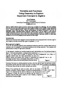
• Using rule 10, create links between the handler’s actuator and each model component’s sensor. • Using rule 11, create a link between F15_Geometry_ Actuator and F15_Dynamic_Sensor, UAV_ Geometry_Actuator and UAV_Dynamic_Sensor, and JSTARS_Geometry_Actuator and JSTARS_ Dynamic_Sensor, respectively. • Using rule 12, create a link between F15_Geometry_ Sensor and F15_Dynamic_Actuator, UAV_ Geometry_Sensor and UAV_Dynamic_Actuator, and JSTARS_Geometry_ Sensor and JSTARS_ Dynamic_Actuator, respectively. Figure 2 shows the overall interaction model structure for the battlefield scene generated from logic rules above. 4. Implementation 4.1 Ontology and Logic Rules An ontology is necessary to define the scene domain and modeling knowledge, as well as formalize and justify connections between geometry and dynamic model components for integrative multimodeling. In addition, logic rules Volume 81, Number 12
Downloaded from http://sim.sagepub.com at PENNSYLVANIA STATE UNIV on April 14, 2008 © 2005 Simulation Councils Inc.. All rights reserved. Not for commercial use or unauthorized distribution.
SIMULATION
801
Park and Fishwick
Interaction Models for F15’s geometry and dynamic objects
Sensor
Controller
Actuator
Fade (Geometry Dynamic)
Sensor
Controller
Actuator
Fade (Dynamic Geometry)
Interaction Models for UAV’s geometry and dynamic objects Interaction Model for Handler’s geometry object
Sensor
Controller
Sensor
Controller
Actuator
Fade (Geometry Dynamic)
Sensor
Controller
Actuator
Fade (Dynamic Geometry)
Actuator
Interaction Models for JSTARS’s geometry and dynamic objects
Sensor
Controller
Actuator
Fade (Geometry Dynamic)
Sensor
Controller
Actuator
Fade (Dynamic Geometry)
Figure 2. Interaction model automatically created through inference rules applied within the ontology in Fig. 1
are needed to induce an interaction model for a certain scene domain. The Protégé ontology editor [32] is employed to create a scene ontology as well as first-order logic rules. OWL and Semantic Web Rule Language (SWRL) are used to construct an ontology and logic rules. And to verify an ontology for a certain scene domain, we use RACER reasoner along with Protégé. Based on the previous ontological structures for the battle scene, we define all the classes and subclasses for the scene domain and modeling knowledge. Also, all necessary relationships (i.e., generalization, association, and aggregation) are specified to represent connections among classes. We define two object-type properties, hasGeometry and hasDynamic, for the Aircraft class to describe a conceptual mapping between components of two models. And for the Battlefield Scene class, two object-type properties, hasGeometryModel and hasDynamicModel, are defined to specify that the battlefield scene has two model types, the two model types can exist together within the same environment, and users can change model representations through an interaction model. To describe classes, we use property restrictions, such as quantifier, cardinality, and hasValue, as well as existential and universal restrictions. Figure 3 shows classes, restrictions, and properties applied to the F15 class. As we mentioned, an interaction model for the battlefield scene could be induced from the scene ontology using
first-order logic rules. Using an inference engine such as Jess, we could inference certain things from domain knowledge in OWL through inference processes. In Protégé, we use SWRL to describe first-order logic rules since SWRL Tab is provided to allow users to create user-defined logic rules. There are a couple of approaches for inference in Protégé: 1. Create first-order logics in SWRL and then perform inference using a Jess rule engine. 2. Write and store logical constraints using Protégé Axiom Language (PAL) and then perform inference using PAL query statements. We use the first approach since SWRL includes a high-level abstract syntax for Horn-like rules. However, the current version of Protégé does not provide inference capability for SWRL. Therefore, we manually generate an interaction model for the battlefield scene based on logic rules at this time.
4.2 Blender Interface To achieve integrative multimodeling in 3D space, we need the following environments:
802 SIMULATION Volume 81, Number 12
Downloaded from http://sim.sagepub.com at PENNSYLVANIA STATE UNIV on April 14, 2008 © 2005 Simulation Councils Inc.. All rights reserved. Not for commercial use or unauthorized distribution.
INTEGRATING DYNAMIC AND GEOMETRY MODEL COMPONENTS
Figure 3. Protégé environment for knowledge base and ontology creation and maintenance
• A customizable dynamic modeling environment that allows modelers to define their own custom metaphors and store them into certain locations or to import proper representations for their dynamic models from libraries of prefabricated geometric model components • A knowledge management environment that enables modelers to extend the scope of a scene domain and/or to create any instances of certain classes or subclasses by providing an ontology editing functionality such as Protégé • A human interaction modeling environment that provides modelers to formalize and execute human interactions so that they can change the representations of the heterogeneous model types
sists of Blender 3D Window (Scene Editor), Blender Interface, and Blender Logic Brick. Geometry and dynamic models for a certain system are composed in the Scene Editor while specifying the dynamic model types and styles for the system and generating Python simulation code for the dynamic model in the Blender Interface. The Python code is inserted into Blender Logic Brick to simulate the dynamic model. In addition, the interaction model, which could be induced through inference processes, is implemented and executed in the Blender Logic Brick for providing a human-computer interaction environment. In the following subsections, the model architecture used in the RUBE library system and each component in Blender Interface, as well as Blender Game Logic, are explained in detail. 4.2.1 Model Architecture
• A simulation/interaction environment that allows modelers to simulate their dynamic models and to enable human-computer interactions We developed a Python-based interface, Blender Interface, which can support these types of environments. Blender Interface consists of four components: Model Explorer, Ontology Explorer, Exporter, and Simulation. Figure 4 depicts the overall integrative multimodeling environment in the Blender software. The environment con-
To use Blender Interface, RUBE must be installed. The RUBE has four folders: Primitive, Predefined Theme, User-Defined Theme, and rube_utility folders. The Primitive and Predefined Theme folders are given for users to provide libraries containing dynamic model objects and the corresponding MXL files and functions. As the names imply, the Primitive folder has primitive Blender objects, such as cube and sphere, with the corresponding MXL file and function for each model type, such as FSM or FBM. Volume 81, Number 12
Downloaded from http://sim.sagepub.com at PENNSYLVANIA STATE UNIV on April 14, 2008 © 2005 Simulation Councils Inc.. All rights reserved. Not for commercial use or unauthorized distribution.
SIMULATION
803
Park and Fishwick
Figure 4. Blender environment containing the game engine
The Predefined Theme folder contains prefabricated customized and personalized Blender objects, as well as MXL files and functions. If modelers want their own model representations, they can create an object and store it into a proper model-type folder under the User-Defined Theme using the Exporter component provided by the Blender Interface. The reason for providing the model component repository (i.e., Primitive, Predefined Theme, and UserDefined folders) is that we give modelers flexibility in model representation. After installing RUBE, the modelers load “Blender_Interface.py” from the rube_utility folder and then execute it to use the Blender Interface, which is shown in Figure 4. For the model architecture, each model type is further divided into its model elements; each element is classified into detailed areas. Likewise, each area is further specified. For example, the FBM folder has two subfolders, Function and Trace, which are elements of FBM. The Function folder has three specific areas: arithmetic, general, and sensor. In arithmetic, the Add_2_1 arithmetic function is found, which has two subfolders according to data types, Integer and Float. There are three files associated with the Add_2_1 arithmetic function for float data. The Python file (i.e., Add_2_1.py) contains the following simple program code (the number “2” in the file name represents the number of input, while the number “1” represents the number of output): def Add_2_1 ( parameter_1, parameter_2):sum = parameter_1 + parameter_2return sum Also, we need 3D objects to explicitly represent geometric elements of dynamic models in 3D space. The
Add_2_1.obj contains the 3D object associated with the function Add_2_1. In this case, the file contains a cube since we want to visualize the block element as a primitive type. The MXL file (i.e., Add_2_1.mxl) contains the following expression to represent semantics of the Add_2_1: The id of the block points to the primitive 3D object, while the func of the script indicates the function “Add_2_1” defined in “Add_2_1.py.” Also, two float input and a float output ports are included. Each low folder in the model architecture contains three files, to represent its functionality, geometry, and semantics in a set of pairs. 4.2.2 Model Explorer Model Explorer reflects the model architecture, as shown in Figure 5, and is used for the dynamic modeling process. It provides flexibility in model presentation and efficiency in model creation to modelers. The concept of Windows Explorer is used for building Model Explorer since most modelers are well acquainted with Windows Explorer. Using Model Explorer, modelers are able to search model objects, which they want to import, within the RUBE fold-
804 SIMULATION Volume 81, Number 12
Downloaded from http://sim.sagepub.com at PENNSYLVANIA STATE UNIV on April 14, 2008 © 2005 Simulation Councils Inc.. All rights reserved. Not for commercial use or unauthorized distribution.
INTEGRATING DYNAMIC AND GEOMETRY MODEL COMPONENTS
Figure 5. A snapshot of Model Explorer
ers. They then generate proper model objects in the specific positions of Blender 3D Editor specified by the modelers. Also, modelers select and import connection objects, such as pipes or arrows, to represent connectivity between main model components. We developed a “snap-to-grid” algorithm to deal with connectivity in 3D space; that is, the algorithm makes scaling, rotation, and transformation matrices for the connection objects using vector operations. Therefore, when given non-connection-related objects in a 3D scene, the modelers do not need to relocate, resize, and rerotate any connection objects. This indicates that the algorithm can place the connection objects exactly between the source and target model components according to the modelers’ requests. Figure 5 shows a graphical user interface for Model Explorer. 4.2.3 Ontology Explorer Ontology Explorer is developed for the following reasons: • Provide an alternate modeling method for dynamic or geometry models • Construct a model component database for reusability by allowing users to create instances of OWL classes or subclasses Like Model Explorer, the concept of Ontology Explorer is similar to that of Windows Explorer. To create Ontology Explorer, XML technologies, such as 4Suite and eXtensible Stylesheet Language Transformations (XSLT), are used since the OWL file is one of XML-related languages. Figure 6 shows the snapshot of Ontology Explorer. In Figure 6, the numbers next to class or subclass names indicate
the number of instances associated with the classes or subclasses. If a modeler clicks a “+” button next to a class or subclass name, geometry and dynamic model components’ location information is displayed, as shown in Figure 6, for modelers to provide an alternative modeling method by importing a stored geometry and/or dynamic objects. When a button is pressed associated with hasDynamic or hasGeometry, the corresponding object will appear in the Blender 3D Editor. In addition, modelers can generate instances of OWL classes or subclasses for maintaining or extending the scope of a scene domain in Ontology Explorer. 4.2.4 Export Export [33] is included in Blender Interface to allow modelers to build their own customized or personalized dynamic objects. Figure 7 shows a graphical user interface for Export. For example, if a modeler wants to build a primitive FBM block with three inputs and one output, which represents an arithmetic integer ADD function, the modeler has to create an object representing a functional block, as shown in Figure 7 in the Blender 3D Editor. The modeler then specifies a location for storing the object and presses the export button in the Export. In addition, the modeler creates MXL, which describes dynamic behavior for the dynamic component, and a Python code for the integer ADD function. The modeler then stores these files in the location where the 3D dynamic object is already stored. Modelers could produce their own MXLs and functions for their customized and personalized model components without having knowledge of MXL and Python syntax since we provide default MXLs and functions in the Volume 81, Number 12
Downloaded from http://sim.sagepub.com at PENNSYLVANIA STATE UNIV on April 14, 2008 © 2005 Simulation Councils Inc.. All rights reserved. Not for commercial use or unauthorized distribution.
SIMULATION
805
Park and Fishwick
Figure 6. A snapshot of Ontology Explorer
Figure 7. Graphical User Interface (GUI) for Export
806 SIMULATION Volume 81, Number 12
Downloaded from http://sim.sagepub.com at PENNSYLVANIA STATE UNIV on April 14, 2008 © 2005 Simulation Councils Inc.. All rights reserved. Not for commercial use or unauthorized distribution.
INTEGRATING DYNAMIC AND GEOMETRY MODEL COMPONENTS
library system. The defaults could give modelers guidelines on generating their own files. 4.2.5 Simulation From given dynamic model components in Blender 3D Editor, we can generate a simulation code for a target system through the RUBE framework. The simulation code is Python scripting language. The process for generating a simulation code includes three steps, as shown in Figure 8: 1. BlenderToMXL: First, an MXL file for a given scene dynamic model is created by gathering all segmented MXL files from the libraries since the library system contains Blender objects, as well as the corresponding MXLs and functions in a set of pairs. 2. MXLToDXL: Using XSLT, the MXL file is converted to a low-level XML language called Dynamics eXchange Language (DXL). 3. DXLToPython: The Python code for simulation is generated from DXL using DOM. Figure 8 shows a Graphical User Interface for Simulation. To simulate a given dynamic model, Blender Game Logic is employed, which is discussed in the following section. Blender Game Logic consists of three components: sensors, controllers, and actuators. The generated Python code is placed within the controllers of a dummy object so that the actuators of the dummy object can distribute current simulation values to sensors of the main dynamic blocks that compose a dynamic model. 4.2.6 Blender Game Logic Blender software provides not only a 3D authoring environment but also a simulation environment called Blender Game Logic. Using Blender Game Logic, modelers interact with a 3D world in real time by controlling scene objects that can interact with other scene objects existing in the 3D world. Sensors, controllers, and actuators are key components for creating a “game.” We can envision the sensors as the senses of a life form, the controllers as the brain, and the actuators as the muscles. On the other hand, we can consider Blender Game Logic as dynamic models. Sensors are FBM blocks with no inputs (they drive or generate the data), controllers are FBM blocks with inputs and outputs, and actuators are FBM blocks with no outputs. Hence, the concepts of the Blender Game Logic could be applied to implement an interaction model for user interactions. We use Blender Game Logic not only for simulating a dynamic model but also for constructing and executing an interaction model. 5. A Military Application In this section, we explain how an integrative multimodeling environment can be implemented through our method-
ology, as proposed in section 3, using an example of the battle scene. In this particular example, three geometry objects represent one UAV, one F15, and one JSTARS, respectively. The objects are flying around and communicating with each other. To avoid simulation complexity, we simplify a simulation scenario, which means UAV passes target information to JSTARS, and then JSTARS commands F15 to attack the target. We can represent the scenario as an FBM. Figure 9 shows the 2D diagram representation for FBM, which can be modeled as a 3D dynamic model using Blender Interface. The UAV block randomly generates a Boolean value (0/1) and sends it to the JSTARS block. If the JSTARS block receives “True,” it conveys the value to the F15 block. The F15 block counts the “True” value as the number of received attack messages. 5.1 Modeling for Geometry and Dynamic Models To create geometry objects in the Blender 3D Editor, there are three possible approaches: • Directly build geometry objects in the Blender 3D Editor • Append geometry objects using Blender menus • Reuse geometry objects by importing class instances from the ontology using Ontology Explorer For the example, the objects are created by the first method since the ontology has no instance initially. To avoid model complexity, geometry objects are placed in the first layer of the Blender 3D scene since Blender provides multiple 3D layers to help modelers create complicated 3D scenes. The dynamic model for the example can be generated in the second layer using Model Explorer or Ontology Explorer. For the example, Model Explorer is used to create dynamic objects since the library system provides essential primitive objects and corresponding MXLs and functions. If modelers want customized or personalized objects, they can create and store their own objects and then import the objects using Export and Model Explorer. In this example, the Primitive folder is selected because we want to represent a dynamic model as a primitive type such as a cube. Then the FBM folder is selected as a model type. Because FBM consists of two model elements, such as function and trace, we have to choose one of the model element folders and then select any proper function or trace types. To represent the first block in Figure 9, the Boolean random generator is selected as Function. If we press the button representing the object file, we can see the corresponding object in the Blender 3D Editor. To represent the first arrow between the first and second blocks in Figure 9, we choose the Trace folder and select “Arrow,” and then we press the object button. As with the first block, the arrow object appears in the scene and is placed exactly between the first Volume 81, Number 12
Downloaded from http://sim.sagepub.com at PENNSYLVANIA STATE UNIV on April 14, 2008 © 2005 Simulation Councils Inc.. All rights reserved. Not for commercial use or unauthorized distribution.
SIMULATION
807
Park and Fishwick
Figure 8. Graphical User Interface (GUI) for Simulation
Figure 9. Two-dimensional dynamic functional block model (FBM) representation of the combat scene
and second blocks since we support the algorithm for topological connectivity called “snap to grid.” All blocks and traces in the 2D diagram can be generated in the same manner as previously explained. If we create new customized dynamic model components to represent the scene, we can store the components for future reuse by creating instances of respective classes in Ontology Explorer. 5.2 Modeling for Interaction Model To achieve integrative multimodeling within the Blender environment, an interaction model for user interactions is necessary since the interaction model allows modelers to manipulate heterogeneous model types in 3D space. The interaction model is simply a dynamic model for modelers who are driving the system. We implement an interaction model as a dynamic model in Blender Game Logic. Based on the induced interaction model, which was
shown in section 3, for the scene, we embody the interaction model, as shown in Figures 10 and 11, within the Blender Game Logic. In the Blender Game Logic, there are sensors, controllers, and actuators. These are used to create “Logic Brick” graphs that drive the interaction. The game engine can cover most interaction behaviors since it has well-defined built-in sensors and actuators. If a user, however, wants more complicated interactions, the user can handle the interactions by Python scripting language. After creating a Python file, the user puts it in one of the controllers and connects the controller with any proper actuator. Figures 10 and 11 show the example of the interaction game logic applied to the F15 (i.e., geometry and dynamic objects for the F15). In addition, one always sensor, one expression controller, and one motion actuator are employed to animate the geometry model. In the same manner, we can apply the interaction logic to other model components, such as the UAV and JSTARS.
808 SIMULATION Volume 81, Number 12
Downloaded from http://sim.sagepub.com at PENNSYLVANIA STATE UNIV on April 14, 2008 © 2005 Simulation Councils Inc.. All rights reserved. Not for commercial use or unauthorized distribution.
INTEGRATING DYNAMIC AND GEOMETRY MODEL COMPONENTS
Figure 10. Interaction model for the F15 (geometry object)
Figure 11. Interaction model for the F15 (dynamic object)
Volume 81, Number 12
Downloaded from http://sim.sagepub.com at PENNSYLVANIA STATE UNIV on April 14, 2008 © 2005 Simulation Councils Inc.. All rights reserved. Not for commercial use or unauthorized distribution.
SIMULATION
809
Park and Fishwick
Figure 12. MXL for the example
5.3 Code Generation The three steps—BlenderToMXL, MXLToDXL, and DXLToPythonCode—are needed to generate a Python-based simulation code from given dynamic model components. First we have to create an overall MXL representation for a certain dynamic model by collecting all individual MXL files, which are associated with dynamic model objects, from libraries. The overall MXL representation for the example is shown in Figure 12. Each block contains certain functional information for the dynamic model, while each trace represents topological connectivity for the dynamic model. The block for JSTARS, for example, has its ID, input and output ports, and function with ID. In the case of a trace, it shows topological connectivity using “from” and “to” attributes. The connection information is automatically generated through the algorithm, “snap to grid.” In addition, simulation information is also shown in the figure. Default values are currently predefined for the simulation attributes. If a user wants to change the values, the user can modify the values in the Blender Interface source code. After MXL is generated, DXL, which is a lower level modeling language, can be created from MXL using MXLToDXLTranslator. The DXL represents a homogeneous dynamic model consisting of block, port, and connect. Then we can produce a Python simulation code through DXLToPythonCode. A 3D dummy object is needed to in-
sert the generated Python code into the controller of the dummy object for simulating the example. After placing the code in the controller, the actuator of the dummy object can distribute current simulation values to each sensor of the dynamic blocks for simulation. Figures 13 and 14 represent a final battlefield scene that contains geometry and dynamic models. Through user interactions, we can convert a geometry model, which is shown in Figure 13, to a dynamic model, which is shown in Figure 14, and vice versa. 6. Conclusions and Future Research In this article, our approach and methodology for integrative multimodeling has been presented. We have explained and discussed the integrative multimodeling environment and graphical user interfaces for the environment. Using the example of the battle scene, we have demonstrated how the integrative multimodeling concepts are applied to a real-world system and how an interaction model could be automatically generated. We learned that effective ontology construction and human-computer interaction techniques are essential factors to support integrative multimodeling. In our research, ontology concepts are employed for defining our scene domain and formalizing the mapping concepts of different model components, as well as building a model component database. User
810 SIMULATION Volume 81, Number 12
Downloaded from http://sim.sagepub.com at PENNSYLVANIA STATE UNIV on April 14, 2008 © 2005 Simulation Councils Inc.. All rights reserved. Not for commercial use or unauthorized distribution.
INTEGRATING DYNAMIC AND GEOMETRY MODEL COMPONENTS
i
Figure 13. Initial scene (geometry model)
13
ii l
(
d l)
Figure 14. Dynamic model
interactions play an especially important role in integrative multimodeling to manipulate a scene. Therefore, we have also presented the concept of an interaction model and implemented the interaction model using first-order logic rules. One of the distinct points in integrative multimodeling is that the Blender Game Engine concepts are applied for building and executing the interaction model. Also, the interaction model can be implemented and executed in a VRML environment since the interaction model is a kind of routing graph. In addition, Model Explorer and Ontology Explorer have been presented as tools for facilitating the modeling process and managing the ontology. Also, the concepts of the “snap-to-gird” and the RUBE library system have been introduced. This work addresses one component for the overall problem of creating complex networks of models—
namely, using an ontology as a means to create a humancomputer interaction model framework so that model components can be interrelated. Many issues regarding multimodels remain, such as effective means of composability and ensuring complete mapping among models and ports. The contributions of this article in the field of modeling and simulation can be summarized as follows: • We provided an integrated modeling and simulation environment: The integrated modeling and simulation environment for geometry and dynamic models has been developed for supporting the viewing and interaction associated with multiple models under a Blender 3D environment and simulating a dynamic model as well as animating a geometry model in the same digital environment. Volume 81, Number 12
Downloaded from http://sim.sagepub.com at PENNSYLVANIA STATE UNIV on April 14, 2008 © 2005 Simulation Councils Inc.. All rights reserved. Not for commercial use or unauthorized distribution.
SIMULATION
811
Park and Fishwick
• We presented an interaction model concept and modeling process for the interaction model: The concept of the interaction model for integrative multimodeling is created and represented as an FBM for formalizing human-computer interactions. “Logic Brick” graphs are used for modeling the interaction model and executing the model. • We provided an improved dynamic modeling environment: The library system and the “snap-to-grid” algorithm are provided for modelers to give flexibility and efficiency in model representation, as well as to facilitate a dynamic modeling process. For future work, four areas of research related to a modeling and simulation, human-computer interaction, and Blender Interface on which we plan to focus our effort include the following: 1. Model-type extension: Currently, we support only two main MXL model types: FSM and FBM. We also plan on supporting the following types: EQN (difference and differential equations), QM (queuing model), PETRI (Petri nets), MARKOV (Markov models), and SD (system dynamics models). 2. Interface construction: Our current work with Blender is preliminary, and the Model and Ontology Explorers need to be fleshed out to make them more robust. 3. Visual programming support: Another member of our research group will develop a visual programming model capability, using a factory metaphor. This will serve as a comprehensive usability test for our research product. 4. Integrative modeling: We will identify key interaction mechanisms that allow geometric and dynamic models to be juxtaposed and connected in the user interface. This will involve the primary two input devices (mouse and keyboard) along with special transitional effects, such as morphing, transparency, and linking. The purpose of this integration is to facilitate interaction networks that ease the connections between scene objects and objects that represent the dynamic model components. 7. References [1] Luebke, D., M. Reddy, J. Cohen, A. Varshney, B. Watson, and R. Huebner. 2003. Level of detail for 3D graphics. San Francisco: Morgan Kaufmann. [2] Gallier, J. 2000. Curves and surfaces in geometric modeling: Theory and algorithms. San Francisco: Morgan Kaufmann. [3] Fishwick, P. A. 1995. Simulation model design and execution: Building digital worlds. Englewood Cliffs, NJ: Prentice Hall. [4] Law, A., and W. Kelton. 1991. Simulation modeling & analysis. New York: McGraw-Hill.
[5] Hoover, S., and R. Perry. 1989. Simulation: A problem-solving approach. New York: Addison-Wesley. [6] Halpin, T. 2001. Information modeling and relational databases: From conceptual analysis to logical design. San Francisco: Morgan Kaufmann. [7] Slooten, K. 2002. Optimal information modeling techniques. Hershey, PA: IRM Press. [8] Fishwick, P. A. 2004. Toward an integrative multimodeling interface: A human-computer interface approach to interrelating model structures. Manuscript accepted for publication. [9] Park, M., and P. A. Fishwick. 2004. A methodology for integrative multimodeling: Connecting dynamic and geometry models. In Proceedings of Enabling Technology for Simulation Science, Part of SPIE Aerosense ’04 Conference. [10] McGuinness, D. L. 2003. Ontologies come of age. In Spinning the semantic web, edited by D. Fensel, J. Hendler, H. Lieberman, and W. Wahlster, 171-94. Cambridge, MA: MIT Press. [11] Roosendaal, T., and S. Selleri. 2004. Blender 2.3 Guide. Amsterdam: Blender Foundation. [12] Roosendaal, T., and C. Wartmann. 2002. The official Blender Gamekit: Interactive 3D for artists. Amsterdam: Blender Foundation. [13] Lacy, L. 2005. Owl: Representing information using the Web ontology language. New Bern, NC: Trafford. [14] Kim, T., J. Lee, and P. A. Fishwick. 2002. A two-stage modeling and simulation process for Web-based modeling and simulation. ACM Transactions on Modeling and Computer Simulation 12 (3): 230-48. [15] Kim, T., and P. A. Fishwick. 2002. A 3D XML-based customized framework for dynamic models. In Proceedings of the Seventh International Conference on 3D Web Technology, pp. 103-9. [16] Berners-Lee, T., J. Hendler, and O. Lassila. 2001. The semantic web. Scientific American, May, 34-43. [17] Bouquet, P., A. Dona, L. Serafini, and S. Zanobini. 2002. ConTeXtualized local ontologies specification via CTXML. In Proceedings of the AAAI Workshop on Meaning Negotiation, pp. 64-71. [18] Kashyap, V., and A. Sheth. 1996. Semantic and schematic similarities between database objects: A context-based approach. The VLDB Journal: The International Journal on Very Large Data Bases, 5 (4): 276-304. [19] Maedche, A., B. Motik, N. Silva, and R. Volz. 2002. MAFRA—A MApping FRAmework for distributed ontologies. In Proceedings of the 13th International Conference on Knowledge Engineering and Knowledge Management, pp. 235-50. [20] Wache, H., T. Voegele, U. Visser, H. Stuckenschmidt, G. Schuster, H. Neumann, and S. Huebner. 2001. Ontology-based integration of information: A survey of existing approaches. In Proceedings of the IJCAI-01 Workshop on Ontologies and Information Sharing, pp. 108-18. [21] Lacy, L., and W. J. Gerber. 2004. Potential modeling and simulation applications of the Web ontology language—OWL. In Proceedings of the 2004 Winter Simulation Conference, pp. 265-70. [22] Miller, J., G. Baramidze, P. A. Fishwick, and A. Sheth. 2004. Investigating ontologies for simulation modeling. In Proceedings of the 37th Annual Simulation Symposium, p. 55. [23] Fishwick, P. A., and J. Miller. 2004. Ontologies for modeling and simulation: Issues and approaches. In Proceedings of the 2004 Winter Simulation Conference, pp. 251-6. [24] Liang, V., and C. Paredis. 2003.A port ontology for automated model composition. In Proceedings of the 2003 Winter Simulation Conference, pp. 613-22. [25] Brown, A. 2004. An introduction to model driven architecture part I: MDA and today’s systems. The Rational Edge, January. www.106.ibm.com/developerworks/rational/library/ 3100105.html [26] Mosterman, P. J., and H. Vangheluwe. 2004. Computer automated multi-paradigm modeling:An Introduction. SIMULATION 80 (9): 433-50. [27] Bernstein, P.A. 2003.Applying model management to classical meta data problems. In Proceedings of CIDR 2003, pp. 209-20.
812 SIMULATION Volume 81, Number 12
Downloaded from http://sim.sagepub.com at PENNSYLVANIA STATE UNIV on April 14, 2008 © 2005 Simulation Councils Inc.. All rights reserved. Not for commercial use or unauthorized distribution.
INTEGRATING DYNAMIC AND GEOMETRY MODEL COMPONENTS
[28] Campbell, B., P. Collins, H. Hadaway, N. Hedley, and M. Stoermer. 2002. Web3D in ocean science learning environments: Virtual big beef creek. In Proceedings of the Seventh International Conference on 3D Web Technology, pp. 85-91. [29] Cubaud, P., and A. Topol. 2001. A VRML- based user interface for an online digitalized antiquarian collection. In Proceedings of the Sixth International Conference on 3D Web Technology, pp. 51-9. [30] Lin, C., and R. Loftin. 1998. Application of virtual reality in the interpretation of geoscience data. In Proceedings of the ACM Symposium on Virtual Reality Software and Technology, pp. 187-94. [31] Hendricks, Z., G. Marsden, and E. Blake. 2003. A meta-authoring tool for specifying interactions in virtual reality environments. In Proceedings of the 2nd International Conference on Computer Graphics, Virtual Reality, Visualization and Interaction in Africa, pp. 171-80. [32] Noy, N. F., M. Sintek, S. Decker, M. Crubezy, R. W. Fergerson, and M. A. Musen. 2001. Creating semantic Web vontents with Protege-2000. IEEE Intelligent Systems 16 (2): 60-71. [33] Lynch, C. http://jmsoler.free.fr/util/blenderfile/py/
Minho Park is an assistant professor of computer science at Stephen F. Austin State University. He received a Ph.D. in computer and information science and engineering in May 2005 from the University of Florida and an M.S. in computer and information science and engineering at the University of Florida in 2002. He worked as a software engineer at Korea Securities Computer Corporation in Korea from 1994 to 1998 and as an assistant manager at Good-Morning Securities Company in Korea from 1999 to 2000. His major research areas are modeling for computer simulation, 3D visualization, and aesthetic computing.
Paul A. Fishwick is a professor of computer and information science and engineering at the University of Florida. He received a Ph.D. in computer and information science from the University of Pennsylvania in 1986 and has 6 years of industrial and government production and research experience (Newport News Shipbuilding and NASA Langley Research Center). His research interests are in computer simulation modeling and analysis methods for complex systems. He is a senior member of the IEEE and a fellow of the Society for Computer Simulation. He is also a member of the IEEE Society for Systems, Man and Cybernetics; the ACM; and the AAAI. He founded the comp.simulation Internet news group (Simulation Digest) in 1987, which has served numerous subscribers. He has chaired several workshops and conferences in the area of computer simulation, including serving as general chair of the 2000 Winter Simulation Conference. He was chairman of the IEEE Computer Society technical committee on simulation (TCSIM) for 2 years (1988-1990), and he is on the editorial boards of several journals, including the ACM Transactions on Modeling and Computer Simulation; IEEE Transactions on Systems, Man and Cybernetics; The Transactions of the Society for Computer Simulation; International Journal of Computer Simulation; and the Journal of Systems Engineering. He has delivered 11 keynote addresses at major conferences relating to simulation. He has published more than 160 technical publications, written one textbook, coedited two Springer Verlag volumes on simulation, and published eight book chapters. He has recently finished editing Aesthetic Computing for MIT Press and is editor of the forthcoming CRC Handbook on Dynamic Systems Modeling.
Volume 81, Number 12
Downloaded from http://sim.sagepub.com at PENNSYLVANIA STATE UNIV on April 14, 2008 © 2005 Simulation Councils Inc.. All rights reserved. Not for commercial use or unauthorized distribution.
SIMULATION
813