courses they will be taking in school and in the long term as life-long ... Applied geometry has been part of engineering design graphics since its inception. Being.
Wiebe, E. N., Branoff, T. J. & Hartman, N. W. (2003). Teaching geometry through dynamic modeling in introductory engineering graphics. Engineering Design Graphics Journal, 67 (2), 12-20.
1
Teaching Geometry through Dynamic Modeling in Introductory Engineering Graphics Eric N. Wiebe Ted J. Branoff Nathan W. Hartman NC State University
ABSTRACT This paper is part of an ongoing set of papers by Wiebe, Branoff, and Hartman looking at how constraint-based 3D modeling can be used as a vehicle for rethinking instructional approaches to engineering design graphics. In particular is the goal of moving from a mode of instruction based on the crafting by students and assessment by instructors of static 2D drawings and 3D models. This approach to instruction results in overemphasis on correct size and style of geometric elements (e.g., the ‘look’ of the graphic), rather than on the underlying problem-solving process used to create the model. Instead, an approach based on dynamic modeling is proposed. This approach provides the opportunities for students to learn about geometry through the embedding of geometric behaviors into models and then testing these behaviors via dynamic change of the model. This approach is better aligned with larger goals of better problem-solving abilities in the technology and engineering workforce. Example instructional activities are presented.
Introduction While 3D constraint-based modeling has been in use in industry for more than ten years, it has only been within the last few years that there has been widespread adoption of these modeling tools at colleges and universities. 3D modeling tools have been identified as a key component of some areas of engineering education for a while (e.g., Barr & Juricic, 1992), but it has only been recently that educators have begun to investigate how the newer constraint-based modeling tools bring a new set of possibilities to instruction (e.g., Ault, 1997). Even more recently, researchers have looked more holistically at how these constraint-based tools can be effectively integrated into a modern engineering graphics curriculum (Baxter, 2001; Branoff, Hartman, & Wiebe, 2002; Cumberland & Miller, 2001). In looking at the curricular implications of these tools, it becomes important to identify what are the core concepts and abilities we intend for students to gain from an introductory course in engineering graphics. The knowledge and abilities gained have to be relevant both in the short term for further courses they will be taking in school and in the long term as life-long learners and productive workers in industry (Connolly, 1999). A particular challenge is to strike a balance between
Wiebe, E. N., Branoff, T. J. & Hartman, N. W. (2003). Teaching geometry through dynamic modeling in introductory engineering graphics. Engineering Design Graphics Journal, 67 (2), 12-20.
2
narrowly defined competencies with particular software tools and larger 'big picture' conceptual knowledge about what drives this whole class of constraint-based modeling tools. Wiebe (1999a, 1999c) has previously outlined the similarities in the underlying functionality between the most popular constraint-based tools and their relatively accessible user interfaces. This trend continues to this day and has largely removed the need to focus large portions of an engineering graphics course to training on specific software packages in order to meet industry needs. Working under this assumption, this article will instead focus on one of the key conceptual areas of modeling that should be emphasized in any modern engineering graphics curriculum: geometry. That is, a primary instructional goal should be the development of students' understanding of Euclidean and topological properties of planar and solid geometry using constraint-based 3D modeling tools, not skills training for specific software tools. Applied geometry has been part of engineering design graphics since its inception. Being applied, however, means that how it is integrated into the curriculum becomes dependent on what tools are being employed and what the perceived needs are for the students in their future education and employment. The introduction of constraint-based modeling into the curriculum means that, once again, there needs to be extensive discussion of how geometry should be applied in this evolving curriculum (Wiebe, 1999b). This paper will outline how applied geometry can be integrated into a modern engineering graphics curriculum. This will include the use of geometric relations within a 3D solid model representing a virtual, engineered product. Of particular interest is the definition of the size and location of a 'feature' in a solid model relative to its constituent features or a frame of reference. These goals are addressed within a framework of a student identifying key geometric features within the virtual product and how this geometry needs to be controlled in order for the model to be of maximum usefulness in the product development process.
Dynamic Modeling Engineering graphics has, in many ways, struggled with the same issues that technology education has over the past 40 years. That is, how to move beyond teaching 'craft' with the end all and be all goal of creating a 'product', to teaching 'process', where how you get to the finished stage is more important than the product itself (McCormick, Murphy, & Harrison, 1993). In other words, the final product and its precursor stages become artifacts that represent the problem-solving process of an applied geometric problem. While a certain level of technical competency with the tools (3D constraint-based modeling tools in this case) is critical in solving the problem, problems need to be designed where critical geometric thinking is also required to arrive at an acceptable solution. It is, however, a challenge to
Wiebe, E. N., Branoff, T. J. & Hartman, N. W. (2003). Teaching geometry through dynamic modeling in introductory engineering graphics. Engineering Design Graphics Journal, 67 (2), 12-20.
3
come up with modeling problems where a 'good solution' can be assessed by measures other than geometric accuracy (Clark & Scales, 2001). Historically, engineering graphics artifacts turned in as part of coursework are assessed by visual inspection. This could mean reading dimensions on a multiview drawing or it could be judging the length, angle, or higher order geometric relations of model elements. The latter, when done with normal views of planar geometry, can often be done with a fairly high degree of accuracy. However, judging these geometric relations in pictorial views can be prone to error (Wiebe & Converse, 1996). Another alternative is electronic measuring of geometry within the computer model. However, this still does not necessarily get past an assessment of the model solely based on the final artifact. An alternative to visual inspection of hard copy printouts or passive inspection on the computer monitor is active probing of the actual computer model. While complete inspection of how the entire model has been constructed and constrained can be very time consuming, focused probing of key features is more effective. Often this probing takes the form of changes of key dimensional values, revealing how the underlying construction of the model responds to these changes. This use of 'dynamic modeling' shows promise as a strategy when the goal of assessment goes beyond geometric accuracy of the final model (Branoff et al., 2002). An interesting variation on the instructor probing the model with dimensional constraint changes is to require the student to produce multiple versions of the model based on instructions provided by the instructor. Here, the challenge will be to design modeling problems that visually reveal the design intent embedded in the model via readily identifiable visual artifacts. Dynamic models as a strategic instructional goal addresses a number of key issues. First, it allows for a broader assessment of the modeling problem that encompasses both 'solution' and 'accuracy'. The modeling design process that leads to the solution is embedded in the model by the way the student chooses to construct their model. These construction decisions are revealed to the instructor through dynamic modeling manipulations. Second, these dynamic modeling activities address the important issue of having instructional activities reflect authentic professional practice. In this case, dynamic modeling can come in the form of 'engineering change orders'. The worth of a model now is based not on a single geometric form, but how well it can be iterated through a number of configurations as it moves through the simulated engineering design process. Students now experience the complete cycle of model definition, comparison to design goals, and modification based on needed changes. The ease of making these geometric modifications are a primary driving force for industry to adopt these constraint-based modeling tools, however, many companies will readily admit that their engineers and designers are often ill-equipped to build robust models that truly capture the geometric design constraints (Wiebe, Norton, Summey, & Howe, 1997).
Wiebe, E. N., Branoff, T. J. & Hartman, N. W. (2003). Teaching geometry through dynamic modeling in introductory engineering graphics. Engineering Design Graphics Journal, 67 (2), 12-20.
4
Successful solutions to modeling problems should hinge on addressing three key elements. First, the solution will depend on correct initial geometry; this is usually as far as most assignments go. Second, it will depend on embedding the correct behaviors via geometric constraint definition. Third, it will depend on correct translation of the initial design constraints and engineering change orders into geometric definitions. This approach, however, is not without challenges. First, can a taxonomy be developed that identifies the core geometric behaviors that all students should master? Second, given the inherently openended nature of most design problems, can a robust enough set of activities be developed that allows for assessment within a practical amount of time and with a high degree of reliability? That is, can modeling problems be designed that have students incorporate these behaviors in a systematic and controlled fashion. The remainder of the paper will address this first challenge while indirectly pointing to solutions to the second.
Embedding geometric behavior As mentioned previously, there is a high degree of uniformity of interfaces and modeling tools across the most popular constraint-based modelers used in instructional settings (Wiebe, 1999a). This uniformity allows for the definition of a generic model creation process that is applicable in a wide range of instructional settings. This modeling process is outlined in detail in Bertoline & Wiebe (2002) and will be used as a basis for the discussion here. Also of note, that while the complete virtual product definition most always involves the creation of assemblies, instructional constraints usually limit an introductory course to focusing on single part modeling. Still, all part modeling should be done in the context of knowing that these parts will eventually be part of a larger assembly. A core part of geometry definition takes place in the sketcher where 2D profiles are defined on a planar surface. These sketches can be defined relative to existing geometry in the model or to other sketch elements. In instruction, emphasis should be made on the fact that two fundamental types of geometric constraints are being placed on the profile. First, explicit constraints in the form of dimensional constraints are defined. These constraints are not static dimensions, but control size or location of a particular geometric element. As such, new values can be assigned to the constraint and a new configuration of the profile (and model) can be evaluated based on other constraints in place. Second, implicit constraints are often applied to the profile based on implied geometric relations between elements in the profile or profile elements and existing geometry. These are fundamental geometric relations such as parallelism, colinearity, same size, etc. These implicit constraints are often applied automatically and not readily apparent to the student. Activities that require students
Wiebe, E. N., Branoff, T. J. & Hartman, N. W. (2003). Teaching geometry through dynamic modeling in introductory engineering graphics. Engineering Design Graphics Journal, 67 (2), 12-20.
5
to evaluate the effect of these constraints and/or modify them helps to make them more salient. Further geometric constraints are applied by the creation of a feature from the sketch profile. The type of Boolean operation applied to the swept profile and the side of the profile sketch loop to apply the operation on is at the heart of any modeling activity. The choice of modeling operation should be part of a larger strategy of how the final geometry is created and what geometric features will need modification for future operations. The sketch plane on which the profile sketch was created also constrains the feature through its orientation and location. Similarly, the direction, transformation type (linear versus revolute), and distance of the sweep also provide geometric constraints that can be used to alter model geometry. Instruction on these geometric constraint tools should not just focus on the tool (e.g., '…here is how you constrain profile edges parallel.'), but also on the end design goals of the part. The starting point should be: What is the functionality of the assembly? Where does this part reside in relation to other parts in the assembly?. And how might this part need to change (geometrically) in the future? From there, a rationale is developed for why the geometry is shaped as it is and how it should be constructed and constrained to provide for certain geometric behaviors under dynamic change. More advanced activities can include behavior definition across parts in an assembly and definition of behaviors via explicit mathematical equations.
Behavior types All model behavior is ultimately based on how the model is constructed. That is, it is based both on the geometry of the model and on how this geometry is constrained relative to other geometry or to itself. Behavior reveals itself through how the model changes form when one or more of its constraints is modified. For example, if the length of a bar is doubled in length, then how the holes in the bar change (or don't change) position is based on the behavior embedded in the model. Model behavior is central to all dynamic modeling activities and correct behavior should be explicitly defined by the modeling problem. It follows that correct (and incorrect) model behavior should be clearly identifiable by the student and the instructor assessing the modeling problem. Which behaviors are central to an introductory engineering graphics course should be identified and integrated in modeling activities. These behaviors appropriate to an introductory course might be called 'basic behaviors'. Most all of these basic behaviors will be based on a single constraint modification that impacts one or two dimensional constraints or geometric relations. Advance behaviors --
Wiebe, E. N., Branoff, T. J. & Hartman, N. W. (2003). Teaching geometry through dynamic modeling in introductory engineering graphics. Engineering Design Graphics Journal, 67 (2), 12-20.
6
those that are based on multiple modifications, impact multiple constraints, or involve equation-driven constraints -- are most likely going to be confined to an advanced course. Changes in a model based on behavior definition can result in two fundamental changes in the model: geometric or topological (Zeid, 1991). Geometric change, as defined here, means change in the size or shape of a geometric feature. Topological change involves the deletion or creation of vertices, edges or faces. This typically implies the whole or partial deletion of previously defined features. The distinction between these two types of changes is important since geometric relations may be defined via other geometry. The deletion of existing geometry can cause previously defined relations to fail -- a common occurrence when engaged in extensive dynamic modeling. Basic behaviors based on geometric relational constraints that students should be exposed to in an introductory course include: - Parallelism - perpendicularity - horizontal and vertical (based on a global coordinate system) - symmetry - same size - colinearity - tangency - alignment/fixing to an existing entity Dimensional constraints that control behavior students should have experience with include: - horizontal, vertical, angular, and aligned control of linear location - size of linear elements - circular/angular size of radial elements - location of reference geometry - internal to sketch - external to existing geometry In order to assure uniformity in behavior of the model, models should be fully constrained. That is, the geometry and topology of the model should be fully defined via a combination of dimensional and geometric relational constraints. Allowing geometry to 'float' gives way to the potential for unpredictable behavior, impacting the ease in which the dynamic modeling assignment can be assessed. Unexpected behavior, in fact, should be a flag to the student and instructor that the student has not fully thought through how this model is to behave and how to properly constrain it so that it exhibits these behaviors under the
Wiebe, E. N., Branoff, T. J. & Hartman, N. W. (2003). Teaching geometry through dynamic modeling in introductory engineering graphics. Engineering Design Graphics Journal, 67 (2), 12-20.
7
prescribed conditions. The flip side of this is that modeling problems need to be designed so that they readily reveal common problems with embedding behavior via constraints.
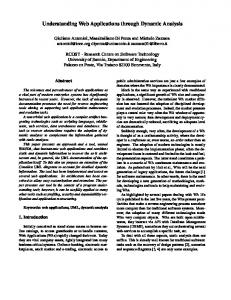
Examples The following are some example modeling problems that could be used in an introductory engineering graphics course. These examples apply the basic geometric behaviors described above to single part models and demonstrate how dynamic modeling techniques can visually reveal their underlying behavior to students. Symmetry
(a)
(b)
(c)
Figure 1. Symmetry. Symmetry as a behavior can be explored using a two-feature model of a plate with a hole in it See Figure 1). An initial plate can be created with a hole in its center, but how the hole behaves under modification can depend on whether the hole was meant to always be centered or offset a fixed distance from one edge of the plate. Here, with a model like this, topological change to the plate where an offset dimensional constraint is attached can be explored. Also, reference planes can be used as a constraining element. If the plate is a mid-plane extrusion from a reference plane, then the plate can expand symmetrically about a fixed hole. A more advanced exercise can show how equations can control the location of the hole. In Figure 1 (a), the initial object is shown as a plate 100 X 40 X 10 mm with a 20mm hole through the center. Examples (b) and (c) show two possible results when the plate size is changed to 70 X 50 mm. In example (b) the hole is located 50mm from the left end and 20mm from the back, so the hole does not remained centered when the overall width and depths are modified. In example (c), plate and the hole are centered on the origin of the part, therefore, changes in the width and depth dimensions keep the hole centered on the plate. This plate can be put in the context of an assembly with the hole aligning with either a stud or fastener and the faces at either end of the 100 mm dimension needing to align with mating faces. Changes to the assembly can be specified as part of a problem that has either Figure 1(b) or 1(c) exhibiting the correct geometric behavior.
Wiebe, E. N., Branoff, T. J. & Hartman, N. W. (2003). Teaching geometry through dynamic modeling in introductory engineering graphics. Engineering Design Graphics Journal, 67 (2), 12-20.
8
Tangency
(a)
(b)
(c)
Figure 2. Tangency. In a sketch profile, whenever a profile has more than one element and at least one of them is a curved element, a decision has to be made concerning tangency. Whether or not a curve is tangent to a straight or curved element may not be readily visible in a static model, but carefully designed dynamic changes can readily reveal a tangent constraint or lack thereof. Problems can be designed to demonstrate how the number of location dimensional constraints needed to fully constrain a curved element changes with the number tangency geometric relational constraints in place. In Figure 2 (a), the front and back surfaces of the object are intended to be tangent to the curved surface. Example (b) illustrates what might happen if a tangency constraint is not present when the depth of the part is changed from 40mm to 30mm. Example (c) represents an object with two tangent constraints. An alternative problem would be to put the plate in an assembly where the radius of the curved element needs to be preserved regardless of the depth of the part. Since most modelers will put in implicit geometric constraints of tangency when the part is initially constructed as seen in Figure 2(a), creating the proper behavior will require explicitly removing the tangency constraint on one or both sides of the curved element in the sketch.
Wiebe, E. N., Branoff, T. J. & Hartman, N. W. (2003). Teaching geometry through dynamic modeling in introductory engineering graphics. Engineering Design Graphics Journal, 67 (2), 12-20.
9
Regular Polygons
(a)
(b)
(c)
Figure 3. Regular Polygons. Creation of a regular polygon from scratch in a profile provides an opportunity to explore symmetry, similar length, and similar angle constraints. Exercises can be designed that explore the differing solutions (e.g., that vary the number of dimensional constraints versus the number of geometric relations) to fully constrain the polygon. Also, the types and number of constraints needed to fully constrain the geometry can vary based on the number of sides and can also vary based on behaviors the polygon needs to exhibit under modification. Figure 3 (a) illustrates starting with a construction circle and two centerlines and 1 1/2 sides of the hexagon. After adding tangent constraints between the circle and the two profile lines, the lines are mirrored about the centerlines and the necessary constraints are added to fully define the polygon as shown in example (b). Another approach, shown in example (c), is to require only a construction circle and ask the students to determine the number of constraints required to fully define the polygon (regular or otherwise). This activity provides an introduction to construction geometry other than sketch planes and the role it plays in structuring final geometry. The regular polygon exercise can be done with the polygon being swept out to form one feature of a multi-feature part (e.g., a bolt), and/or having the part in the context of a larger assembly. An assembly could be designed requiring a hexagonal feature that was not based on a regular hexagon. In this case, a student would need to more selectively establish a combinations of equal size, equal angle, or symmetry constraints. Additional challenge can be added by requiring the hexagonal shape to driven by dimensional constraints located on specific faces.
Wiebe, E. N., Branoff, T. J. & Hartman, N. W. (2003). Teaching geometry through dynamic modeling in introductory engineering graphics. Engineering Design Graphics Journal, 67 (2), 12-20.
10
Driving 3D Geometry with 2D Sketches
(a)
(b)
Figure 4. Driving 3D Geometry with 2D Sketches.
(a)
(b)
Figure 5. Modifying the Model and Breaking Constraints. Another powerful exercise for students is one where they are required to use 2D sketch data to drive 3D features. Figure 4 shows an object where the depth of the part is driven by the 60mm diameter dimension for the cylinder. Figure 5 (a) illustrates what happens when the diameter is changed to 45mm if the correct tangent constraints are present between the horizontal plate and the cylinder. Figure 5 (b) shows the same modification when the student is required to break the tangent constraint. As with the tangency example above, the spherical surface can be made tangent to the cylinder or not, depending on how the design requirements are specified.
Conclusion A modern engineering graphics curriculum needs to move beyond the crafting of static models and drawings derived from such models. To do so, one needs to begin with a clear taxonomy of geometric behaviors derived from dimensional and relational constraints
Wiebe, E. N., Branoff, T. J. & Hartman, N. W. (2003). Teaching geometry through dynamic modeling in introductory engineering graphics. Engineering Design Graphics Journal, 67 (2), 12-20.
11
applied to the model. Problem-solving oriented modeling assignments that demand dynamic manipulation of the models provides a vehicle for revealing model behaviors to the students and the instructors assessing the student work. Assessment based on dynamic modeling assignments provides the opportunity to judge the quality of the model problem solution, both on the modeling process and the end product. Increasingly, industrial use of constraint-based modelers depends on the creation of sophisticated virtual products that represent multiple geometric configurations of current products and the embedding of geometric behaviors that represent engineering design constraints (Courter, 1999; PTC, 2000; Versprille, 2001). 'Smart' models that reflect critical design constraints allow for rapid creation of new versions of the product and saves companies considerable time and money. Increasingly, employers will demand graduating students who are able to create these sophisticated models. For students learning modeling in this dynamic, problem-based environment, there will be the added benefit of being able to experience engineering design from the standpoint of geometric problem-solving. This will provide an essential counterpoint to classes engineering students already take where much of the problem-solving is numerically based. These changes in the engineering graphics curriculum need to be implemented in such a way that they not create undue burden on instructors, otherwise, they simply will not be adopted. Dynamic modeling problems that allow reliable assessment through visual inspection of different iterations of a model or simple probing of the electronic model are indeed possible. All of the examples given above demonstrate behaviors that are clearly visible in pictorial views of the model, either in printouts or on the screen. The key will be to tightly define the design problem and what constitutes 'correct behavior'. Careful selection of models, geometric definitions, and required modifications will all result in a quality instructional experience.
References Ault, H. (1997). Principles of parametrics - New concepts for the EDG curriculum. Paper presented at the ASEE Engineering Design Graphics Division Mid-Year Meeting, Madison, WI. Barr, R. E., & Juricic, D. (1992). A new look at the engineering design graphics process based on geometric modeling. Engineering Design Graphics Journal, 56(3), 18-26. Baxter, D. H. (2001). Expanding the use of solid modeling throughout the engineering curriculum. Engineering Design Graphics Journal, 65(1), 6-13. Bertoline, G. R., & Wiebe, E. N. (2002). Fundamentals of graphics communication ( 3rd ed.). New York, NY: McGraw-Hill.
Wiebe, E. N., Branoff, T. J. & Hartman, N. W. (2003). Teaching geometry through dynamic modeling in introductory engineering graphics. Engineering Design Graphics Journal, 67 (2), 12-20.
12
Branoff, T. J., Hartman, N. W., & Wiebe, E. N. (2002). Constraint-based, threedimensional solid modeling in an introductory engineering graphics course: Reexamining the curriculum. Engineering Design Graphics Journal, 66(1), 5-10. Clark, A. C., & Scales, A. Y. (2001). Assessment practices in engineering/technical graphics. Engineering Design Graphics Journal, 65(3), 13-24. Connolly, P. (1999). CAD software industry trends and directions. Engineering Design Graphics Journal, 63(1), 26-33. Courter, B. (1999). Conceptual engineering: CAD tools that promote invention (White Paper): PTC, Inc. Cumberland, R. R., & Miller, C. L. (2001). The foundation of a progressive engineering graphics curriculum. Paper presented at the Engineering Design Graphics Division Mid-Year Meeting, San Antonio, TX. McCormick, R., Murphy, P., & Harrison, M. (1993). Teaching and learning technology. Wokingham, England ; Reading, Mass.: Addison-Wesley/Open University Press. PTC. (2000). Behavioral modeling (White Paper): PTC, Inc. Versprille, K. (2001, March). Capturing intent is essential to design reuse. Computeraided Engineering, 56. Wiebe, E. N. (1999a). 3-D constraint-based modeling: Finding common themes. Engineering Design Graphics Journal, 63(3), 15-31. Wiebe, E. N. (1999b). Future applications of geometry and graphics. Engineering Design Graphics Journal, 63(2), 13-20. Wiebe, E. N. (1999c). What's Involved with Moving from One 3-D Constraint-based CAD System to Another? Paper presented at the ASEE Engineering Design Graphics Division Mid-Year Meeting, Biloxi, MS. Wiebe, E. N., & Converse, S. A. (1996). Recognition of shape and metric changes in 3-D computer models. Paper presented at the Human Factors and Ergonomics Society 40th Annual Meeting, Philadelphia, PA. Wiebe, E. N., Norton, J. J., Summey, J., & Howe, J. E. (1997). Organizational assessment of integrating CAD and product data management tools in the furniture industry (Technical Report 1997-3): Raleigh, NC: North Carolina State University, Furniture Manufacturing and Management Center. Zeid, I. (1991). CAD/CAM theory and practice. NY: McGraw-Hill.