TM and retiming (RT) [26] [27][8][9]. 3. RT and ... synthesis steps possible for practical circuits are the following;. 1. ... node there is a list of equivalent nodes, which compute the ... sequence are thrown away and only the âbestâ one is kept. 2. ..... 531-536. [32] J. S. Zhang, S. Sinha, A. Mishchenko, R. Brayton, and M.
Integrating Logic Synthesis, Technology Mapping, and Retiming Alan Mishchenko
Satrajit Chatterjee
Jie-Hong Jiang
Robert Brayton
Department of Electrical Engineering and Computer Sciences University of California, Berkeley {alanmi, satrajit, jiejiang, brayton}@eecs.berkeley.edu
Abstract This paper discusses a synthesis approach, which combines logic synthesis, technology mapping, and retiming into a single integrated flow. The same combination of methods with minor modifications is applicable in the context of both standard cell and FPGA designs. The implementation draws on new results in representing circuit functions with And-Inv Graphs (AIGs) and, based on our experience, should scale to circuits with thousands of memory elements.
1 Introduction and Previous Work In recent years, the development of logic synthesis algorithms has reached a point of convergence, leading to the integration of different aspects of the synthesis process. This tendency is motivated by the shrinking of DSM technologies, which forces more of the synthesis aspects to be considered as interrelated and computed simultaneously. Some recent examples of this convergence can be found in the research work trying to integrate: 1. Technology independent synthesis (TIS) and technology mapping (TM) [18][24][30] 2. TM and retiming (RT) [26] [27][8][9] 3. RT and placement (PL) [1][6] 4. Re-synthesis (RS) and RT [25] 5. TIS and PL [2][15][13] 6. Re-wiring and PL [5] 7. Clock skewing and PL [13] In this paper, we propose to merge TIS, TM, and RT, so that, in theory, the best combination of the three methods can be found in the cross-product of the individual search spaces. This is in contrast to the traditional synthesis approach where these steps are done in sequence. First, TIS is applied to find a network, which is best according to some heuristic criteria, such as the number of literals and logic levels. Next, this information is used to find the best mapping of the current logic structure, and finally, in some cases, retiming of the mapped circuit is performed to optimize delay. Obviously, choices made at the earlier stages bias those made later. Usually a different cost function is used in each stage. This cost function is at best a crude heuristic trying to predict the effects on the later stages. In the new approach, TM finds the best clock period using all available circuit structures and all possible
retimings. Other parameter can be optimized under the delay constraint using parameter-specific cost functions. The techniques that make the proposed convergence of synthesis steps possible for practical circuits are the following; 1. And-Invertor Graphs (AIGs) [16][17] 2. Simulation combined with SAT for efficient functional reduction of AIGs in the FRAIG package [12][23][30] 3. Choice nodes [18] 4. Fast TM methods [3][24] 5. Supergates [22][24] 6. Loop count invariance and optimum retiming [29][6] AIGs provide a uniform method for representing and manipulating logic. In the FRAIG package that we use, the AIGs are made “semi-canonical”, meaning that any two nodes representing the same function are identified. This is done on-the-fly in the FRAIG package. It allows for a compact representation for both synthesis and equivalence checking. The resulting AIG is referred to as a FRAIG below. This common representation facilitates the merging the three operations, TIS, TM, and RT. A FRAIG [23] represents a multi-network since at any node there is a list of equivalent nodes, which compute the same logic function but has a different AIG structure All FRAIGs are stored in the FRAIG manager, which borrows many techniques from an efficient BDD package, such as node hashing, reference counting, garbage collection, and using complemented edges. Combining simulation with SAT allows for a fast on-thefly equivalence checking, which leads to an efficient identification of equivalent nodes in the FRAIG manager. Experimental results in [23] show that the ability of the FRAIG package to find functional equivalences in the typical benchmark circuits compares well with that of the state-of-the-art academic equivalence checkers. Choice nodes were introduced in [18] to combine, during TM, algebraic restructuring (part of TIS), which creates equivalent structures using the associative and distributive laws of Boolean algebra. This was a step towards unbiasing the choice of the structure made during TIS. In our opinion, the use of choice nodes leads to a fundamental shift in paradigm for logic synthesis, which we call “lossless logic synthesis”. This paradigm shift is illustrated by the following discussion: 1. Classical approach. During logic synthesis, a sequence of operations is performed. At each step, the best choice is made, based on a heuristic measure of
quality of the entire network. Thus, the initial network evolves as a sequence of ever “improving” networks. However, intermediate networks generated along this sequence are thrown away and only the “best” one is kept. 2. New approach. In this, the choices of which logic structure is later used for TM, are postponed. We merely generate, record, and merge any new structures into the FRAIG manager. In this, it is critical to have a fast equivalence checking mechanism, such as a balanced combination of simulation and SAT [30]. As a result, TIS becomes a process of generating new structures, without making judgment on their value for TM. Indeed, different networks may contain different good sub-structures. Thus, TIS should be focused on generating “orthogonal” structures, so that a variety of structures could be seen when the actual choices are made during TM. For example, the approach of “collapse as much as possible and decompose” seems orthogonal to the approach “keep around the original nodes that have reasonable values”. This idea was suggested already in [18]. Technology mapping (TM) is applied to the FRAIG obtained after the TIS step. In our approach, this multinetwork replaces the single network obtained at the end of the classical TIS step. Since the FRAIG may contain many choice nodes and, therefore, alternate structures, TM must be done extremely efficiently, both in terms of speed and quality of results. This is where a fine-tuned technology mapper is required. We will see that this approach can be extended to allow RT on sequential circuits. Supergates [3] refer to “new” gates formed using the combinations of gates from the given standard cell (SC) library. This is a one-time preprocessing step applied the SC library and allows for a type of Boolean mapping to be performed during TM. In effect, it extends the structural information present in the FRAIG manager. For example, a supergate may be matched at a node when its set of contained library gates does not find a corresponding match in the fanin FRAIG structure because the appropriate structure is not present at the node. A well-known result about RT is that it preserves the number of registers around any loop (loop count). Recently the converse was proved, i.e. that any pair of isomorphic graphs with identical loop counts can be retimed into each other [6]. This leads to the possibility of ignoring the register positions and just recording, for any new loop generated during TI, an induced loop count (using the notion of peripheral retiming [21]). Once TM chooses a final network, the loop counts can be used to put the registers into any set of places, such that the loop counts are satisfied. In [6], it is shown how to do this constructively. Further, a result in [29] states that from this initial placement of the registers, the network can always be retimed so that the clock cycle can be set (within one gate delay) to be the maximum delay (loop) ratio (the total delay
around a loop divided by the loop register count). It is well known that the maximum delay ratio is a hard bound on the performance of a network. This delay ratio depends on how the network is synthesized and mapped. In our approach, we find the best delay ratio using all available TIS and TM choices. The above considerations lead to our procedure for integrating TIS, TM, and RT, outlined below. 1. Convert the initial network into a FRAIG using SOP or factored form representations of the node functions. 2. “Remove” all registers but mark their initial positions in the FRAIG. At this point, the FRAIG becomes a cyclic combinational circuit. 3. Apply logic re-synthesis transformations to a selected fragment of the FRAIG. 4. Merge the result of re-synthesis into the FRAIG manager, marking a set of compatible register positions in the new result, derived using peripheral retiming. 5. Repeat Steps 3 and 4 with the aim of generating “orthogonal” structures until a limit on runtime or the number of structural alternatives has been reached. 6. Set an initial clock cycle time to a guess at an achievable upper-bound φ , computed by Howard’s algorithm [11]. 7. Apply Pan’s procedure [25] (described in Section 2) to the FRAIG, where the RS is replaced by our minimum delay TM. 8. Do a binary search for the optimum clock cycle by repeating Step 7 with improved guesses on clock period. 9. Infer loop counts on the final mapped network and place the registers in the derived network to satisfy the loop counts. 10. Retime these latches so that the optimum mapped network can be clocked at its optimum clock period (maximum delay ratio). 11. Compute the sequential required times and heuristically recover area and other parameters, as described in [24]. 12. Reduce the number of registers by min-area delayconstrained retiming using an exact ILP formulation [19] or a greedy heuristic approach similar to [30]. Some additional comments elaborate on these steps. • The fragments, to which the synthesis is applied, must satisfy two constraints. It must not contain a reconvergent path where the register counts on reconverging paths differ. This means that the selected fragment is peripherally retimable [20][21]. The fragment can include cycles (some registers are visited more than once), can have many roots (outputs), and can contain choices. • The inferred register marking of the resynthesized fragment is the result of a peripheral retiming of the
registers in the fragment. Negative registers are allowed. When the result is merged into the FRAIG manager, the appropriate register markings will be set at the periphery, which contains the inputs and outputs of the fragment. • The technology mapping step is performed by computing a set of cuts at each node in the cyclic circuit as done in [26], followed by Boolean matching with implicit phase assignments [3]. • When this process converges, we can insert registers into the network according to the method of Chong [6] using the inferred loop counts, and retime these to obtain the clock period equal to the largest delay ratio according to the theorem of Papaefthymiou [29]. In practice, this step is simplified by propagating the latch markings on the graph edges during RS and TM. A typical simplified procedure for latch insertion after FPGA mapping can be found in [27]. • Since the above synthesis and mapping are done to minimize the maximum delay ratio, area is sacrificed. This can be recovered e.g. by computing the sequential required-time in a way similar to how sequential arrival-times are computed in [26] and by applying algorithms for area recovery [24]. Area recovery can also be done by retiming registers not on the critical loops using a fast heuristic algorithm similar to the algorithm for extracting two-cube divisors from the SOP representations of the nodes [30].
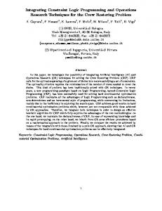
2 Pan’s Algorithm In this section, we outline some results of Pan, which are key to the merging of the RT step with TIS and TM. The first result shows how to integrate retiming and re-synthesis [25]. This was applied to a network with registers and a given set of fanin cones at each node of the network. Each cone is re-synthesized according to its input arrival times in order to minimize its output arrival time. This resynthesis then gives an input-pin to output-pin delay for each input of the cone. The computation of the sequential arrival times is done using the Bellman-Ford style iteration in Figure 1. It is assumed that the clock period φ is known. Procedure update(v) computes, for each re-synthesized cone at v, a new arrival-time l-value as follows: lc (v) = max {l (u ) − tuvφ + duv } u∈input ( c )
where tuv is the number of registers between input u and output v, and duv is the pin-to-pin combinational delay between u and v for the newly re-synthesized cone c. Finally, the procedure returns the minimum of lc(v) over all cones rooted at v, min {lc (v)} . c∈Cones ( v )
At each return visit to a node v, the new arrival times on the inputs of any of a cone may affect how it is synthesized for minimum delay. The iteration continues until there is no change in any of the labels l. We can think of resynthesis in this context as any combination of TIS or TM for the cone,
so in effect, this method is already doing a type of integration of re-synthesis, re-mapping, and retiming. ReRe (G, φ) // G is the circuit, and φ is the cycle time for each node v in G do if v is a PI then l(v) ← 0 else l(v) ← −∞ while (labels changed) do for each non-PI node v in G do ltmp ← update(v) if ltmp > l (v) then l (v) ← ltmp
if v is a PO and l (v) > φ then return FAILURE return SUCCESS; Figure 1: Computation of arrival-time l-values. The following result is stated [25]. If the update operation is monotone increasing (i.e. if any label is increased for the inputs of a cone, then the output label is not decreased), then the sequence of labels computed by the algorithm is monotone increasing. This leads to the result that the algorithm returns SUCCESS if and only if φ is a feasible clock period. In papers on FPGA synthesis [26][27], Pan states that the delay-optimum retiming of the mapped circuit is given by v is a PI or PO 0 r (v) = l opt (v) φ
−1
where r is the retiming lag for each node. Pan refers to the l-values as continuous retiming [28]. We will use this algorithm with the iterative re-mapping technique discussed in [24], which uses an efficient method for computing all cuts of a node up to a certain limit (say, 5 or 6). This computation is performed on the FRAIG representation and easily generalizes to the case when choice nodes are present. The choices nodes effectively increase the number of cuts computed using the alternative structural representations, but otherwise do not impact TM. The cut computation for the case of a cyclic network is given in [26]. Essentially, the cut computation is iterated for the network in such a way that the set of cuts for each node grows in a monotonically increasing sequence. Initially, all cut sets are initialized to the set, which includes the node itself, i.e. C (v) = {{v}} . Then each node is visited and the cut sets of its children are merged by taking the cross-product of the cut sets of the two children. Duplicated sets are eliminated, as well as those cuts whose cardinality exceeds the upper bound. For a choice node, there is no cross-product operation but rather the union of the cut sets of its predecessors is taken, again eliminating duplicates. This iteration continues until there is no change in the set of cut sets, C(v), at any node. It should be noted that all choice nodes are ignored from this point on since the unions of the cut sets {C (v)} actually contain all the useful information about choice nodes as far as TM is concerned.
The cut computation can be stopped before the cut sets, C(v), converge to the fixed point. In this case, the results of mapping are correct but not optimum because we may have skipped the cuts leading, which lead to a better mapping. Although optimality can be weakened, early termination can save runtime.
3 Re-Synthesis In this section, we elaborate on the application of Pan’s algorithm in our proposed approach. The FRAIG represents the alternate structural choices derived during the TIS step. Since the decision about what structure should be used has been postponed to the TIS step, TM using the cut sets derived from the FRAIG with choice nodes represents an integrated combination of TIS and TM. In contrast to Pan’s approach [25], in which each cone is re-synthesized and mapped individually and then the best taken, Step 7 of the new procedure simultaneously evaluates all combinations of the available choices and chooses the best one. In Step 8, instead of searching for an optimum clock cycle, a desired clock cycle can be given, in which case only one iteration of TM is needed if the algorithm returns SUCCESS. Otherwise, either a search for the clock cycle nearest to the desired one can be done, or more structural choices can be generated and recorded in the FRAIG. These new choices can be added selectively using the best mapping seen so far to try to improve the critical paths.
4 Area Recovery The efficient approach to area recovery [24] uses the concept of combinational slack. This concept needs to be extended to work in the sequential domain. In our discussion in Section 2, we computed only the sequential arrival times of the nodes, which represent the arrival times after retiming. The computation of sequential required-time in the cyclic circuits starts at the POs and proceeds backwards in a topological order. For this, we use a modified version of Pan’s algorithm shown in Figure 2: ReReq (G, φ) // G is the circuit, and φ is clock period for each node v in G do if v is a PO then ρ (v) ← φ else l(v) ρ (v) ← ∞ while ( ρ 's have changed ) do for each non-PI node v in G do ρtmp ← update(v)
if ρtmp < ρ (v) then ρ (v) ← ρtmp if v is a PI and ρ (v) < 0 then return FAILURE return SUCCESS; Figure 2: Computation of required-time l-values.
Then, the slack at a node is computed as s (v) = ρ (v) − l (v) . It should be noted that all the mappings were done for minimum delay and hence area might be excessive. However, the area recovery methods of [24] have been shown to be very effective, so we expect that most of the wasted area can be recovered. Iterative optimization of other parameters, such as power and placeability of the netlist after technology mapping, can be performed similarly to area recovery, as shown in [24].
5 Conclusions and Future Developments We have discussed an algorithm, which integrates the steps of technology independent logic synthesis, technology mapping, and retiming. The result, in theory, should be the best mapped network derived by applying all possible combinations of these steps (minimum area for minimum clock period). It is possible that practical constraints on the number of cuts generated or the number of iterations performed in the algorithms of Figures 1 and 2, will modify the claim to be a “heuristically best mapping over all generated logic structures with all possible retimings”. The following aspects of the new optimization flow still have to be developed: 1. Efficient generation of structural choices for sequential networks. Our current procedures for the generation of structural choices work for combinational networks only. We consider extending them to sequential networks by combining the combinational choices derived for the original network and a network with a shifted latch boundary. An alternative way of adding choices is to perform a sequence of local synthesis steps, each of which peripherally retimes latches out of a logic cone, collapses the cone, and decomposes it to get a new logic structure that is added to the network as a choice. During peripheral retiming, we retime over the choice nodes as if they were ordinary OR-gates. 2. Efficient updating of timing information during area recovery for sequential circuits. During area recovery, unlike acyclic circuits, cyclic circuits have no starting and ending points. For acyclic circuits, if the area is recovered from inputs to outputs, the required time does not change and, therefore, need not be recomputed. However, for a cyclic circuit, it may be necessary to recompute a subset of both sequential arrival and required times whenever a node is changed. An efficient method for updating them incrementally is required for cyclic circuits. 3. Speed of convergence of iterative procedures. The Bellman-Ford procedure in Section 2 is iterated several times until an acceptable clock period is found. Since this involves repeated TM, the rate of convergence may be slow. In this case, we need to develop specialized methods for speeding up the convergence.
One possibility is to use Howard’s algorithm [11] to estimate the critical cycles and avoid re-mapping of the non-critical nodes. Ultimately, the efficacy of this approach depends on the implementation and on the set of heuristics used to filter out the unnecessary operations. If an efficient implementation is found, the proposed synthesis framework will explore, in a reasonable time, the combined optimization space of TIS, TM, and RT for sequential circuits with thousands of memory elements.
Acknowledgements This research was supported in part by NSF contract, CCR-0312676, by the MARCO Focus Center for Circuit System Solution under contract 2003-CT-888 and by the California Micro program with our industrial sponsors, Fujitsu, Intel, Magma, and Synplicity. We specially thank Peichen Pan for extensive discussions and pointing us to his pioneering papers.
References [1] T. F. Chan, J. Cong, T. Kong, and J. R. Shinnerl, “Multilevel optimization for large-scale circuit placement”. Proc. ICCAD ’00, pp. 171-176. [2] S. Chatterjee and R. Brayton, “A new incremental placement algorithm and its application to congestion-aware divisor extraction”, Proc. ICCAD ’04, pp. 541-548. [3] S. Chatterjee, A. Mishchenko, R. Brayton, X. Wang, and T. Kam, “Reducing structural bias in technology mapping”, Proc. IWLS ‘05. [4] D. Chen, J. Cong. “DAOmap: A depth-optimal area optimization mapping algorithm for FPGA designs”. Proc. ICCAD ’04, pp. 752-757. [5] P. Chong, Y. Jiang, S. Khatri, F. Mo, S. Sinha, R. Brayton, “Don't care wires in logical/physical design”, Proc. IWLS ’00, pp. 1-9. [6] P. Chong, R. Brayton, “Characterization of feasible retimings”, Proc. IWLS ‘01, pp. 1-6. [7] J. Cong and Y. Ding, “FlowMap: An optimal technology mapping algorithm for delay optimization in lookup-table based FPGA designs”, IEEE Trans. CAD, vol. 13(1), January 1994, pp. 1-12. [8] J. Cong and C. Wu, “An efficient algorithm for performanceoptimal FPGA technology mapping with retiming”, IEEE Trans. CAD, vol. 17(9), Sep. 1998, pp. 738-748. [9] J. Cong and C. Wu, “Optimal FPGA mapping and retiming with efficient initial state computation”, IEEE Trans. CAD, vol. 18(11), Nov. 1999, pp. 1595-1607. [10] J. Cong, C. Wu and Y. Ding, “Cut ranking and pruning: Enabling a general and efficient FPGA mapping solution,” Proc. FPGA `99, pp. 29-35. [11] A. Dasdan, “Experimental analysis of the fastest optimum cycle ratio and mean algorithms”, ACM TODAES, Oct. 2004, vol. 9(4), pp. 385-418. [12] M. K. Ganai, A. Kuehlmann, “On-the-fly compression of logical circuits”, Proc. IWLS ’00. [13] W. Gosti, S. Khatri and A. Sangiovanni-Vincentelli. “Addressing the timing closure problem by integrating logic optimization and placement”, Proc. ICCAD‘01, pp. 224-231.
[14] A. P. Hurst, P. Chong, A. Kuehlmann, “Physical placement driven by sequential timing analysis”. Proc. ICCAD '04, pp. 379-386. [15] Y. Jiang and S. Sapatnekar. “An integrated algorithm for combined placement and libraryless technology mapping,” Proc. ICCAD ’99, pp. 102-106. [16] A. Kuehlmann, V. Paruthi, F. Krohm, M. K. Ganai, “Robust Boolean reasoning for equivalence checking and functional property verification”, IEEE TCAD, Vol. 21(12), Dec 2002, pp. 1377-1394. [17] A. Kuehlmann, “Dynamic transition relation simplification for bounded property checking”, Proc. IWLS ’04, pp. 208215. [18] E. Lehman, Y. Watanabe, J. Grodstein, and H. Harkness, “Logic decomposition during technology mapping,” IEEE Trans. CAD, Vol. 16(8), 1997, pp. 813-833. [19] N. Maheshwari, S. Sapatnekar. “Efficient retiming of large circuits”, IEEE Trans VLSI, Vol. 6(1), March 1998, pp. 7483. [20] S. Malik, E. Sentovich and R. Brayton and A. SangiovanniVincentelli, “Retiming and resynthesis: Optimizing sequential networks with combinational techniques”, IEEE Trans. CAD, vol. 10(1), Jan. 1991, pp. 74-84. [21] S. Malik, K.J. Singh, R. K. Brayton and A. SangiovanniVincentelli, "Performance optimization of pipelined logic circuits using peripheral retiming and resynthesis", IEEE Trans. CAD, Vol. 12(5), May 1993, pp. 568-578. [22] A. Mishchenko, X. Wang, T. Kam, “A new enhanced constructive decomposition and mapping algorithm”, Proc. DAC ‘03, pp. 143-147. [23] A. Mishchenko, S.Chatterjee, R. Jiang, R. Brayton, “FRAIGs: A unifying representation for logic synthesis and verification”, ERL Technical Report, EECS Dept., UC Berkeley, March 2005. [24] A. Mishchenko, S. Chatterjee, R. Brayton, and M. Ciesielski, “An integrated technology mapping environment”, Proc. IWLS ’05. [25] P. Pan, “Performance-driven integration of retiming and resynthesis”, Proc. DAC ’99, pp. 243-246. [26] P. Pan and C.-C. Lin, “A new retiming-based technology mapping algorithm for LUT-based FPGAs”, Proc. FPGA ’98, pp. 35-42. [27] P. Pan and C. L. Liu, “Optimum clock period FPGA technology mapping for sequential circuits”, Proc. DAC ‘96, pp. 720-725. [28] P. Pan, “Continuous retiming: Algorithms and applications. Proc. ICCD ‘97, pp. 116-121. [29] M. Papaefthymiou, “Understanding retiming through maximum average-delay cycles”, Mathematical Systems Theory, No. 27, 1994, pp. 65-84. [30] J. Rajski, J. Vasudevamurthy, “The testability-preserving concurrent decomposition and factorization of Boolean expressions”, IEEE Trans. CAD, Vol.11 (6), June 1992, pp.778-793. [31] L. Stok, M. A. Iyer, A. J. Sullivan, “Wavefront technology mapping”, Proc. DATE ’99. pp. 531-536. [32] J. S. Zhang, S. Sinha, A. Mishchenko, R. Brayton, and M. Chrzanowska-Jeske, “Simulation and satisfiability in logic synthesis”, Proc. IWLS ’05.