This transformation is based on implicit retiming across logic blocks and fanout stems during logic optimization. Its applica- tion to sequential network synthesis ...
Retiming-Based Factorization for Sequential Logic Optimization SURENDRA BOMMU Synopsys, Inc. NIALL O’NEILL Compaq and MACIEJ CIESIELSKI University of Massachusetts
Current sequential optimization techniques apply a variety of logic transformations that mainly target the combinational logic component of the circuit. Retiming is typically applied as a postprocessing step to the gate-level implementation obtained after technology mapping. This paper introduces a new sequential logic transformation which integrates retiming with logic transformations at the technology-independent level. This transformation is based on implicit retiming across logic blocks and fanout stems during logic optimization. Its application to sequential network synthesis results in the optimization of logic across register boundaries. It can be used in conjunction with any measure of circuit quality for which a fast and reliable gain estimation method can be obtained. We implemented our new technique within the SIS framework and demonstrated its effectiveness in terms of cycle-time minimization on a set of sequential benchmark circuits. Categories and Subject Descriptors: B [Hardware]: ; B.6 [Hardware]: Logic Design General Terms: Algorithms, Design Additional Key Words and Phrases: Finite state machines, retiming, sequential synthesis
1. INTRODUCTION Over the years, sequential circuit synthesis has been a subject of intensive investigation. Although synthesis of combinational logic has attained a significant level of maturity, sequential circuit synthesis has been lagging behind. This can be attributed mainly to the increase in circuit complexity
Authors’ addresses: S. Bommu, Synopsys, Inc., Marlboro, MA 01752; N. O’Neill, Compaq, Shrewsbury, MA 01545; M. Ciesielski, Department of Electrical & Computer Engineering, University of Massachusetts, Amherst, MA 01003. Permission to make digital / hard copy of part or all of this work for personal or classroom use is granted without fee provided that the copies are not made or distributed for profit or commercial advantage, the copyright notice, the title of the publication, and its date appear, and notice is given that copying is by permission of the ACM, Inc. To copy otherwise, to republish, to post on servers, or to redistribute to lists, requires prior specific permission and / or a fee. © 2000 ACM 1084-4309/00/0700 –0373 $5.00 ACM Transactions on Design Automation of Electronic Systems, Vol. 5, No. 3, July 2000, Pages 373–398.
374
•
S. Bommu et al.
caused by registers and feedback connections and to the deficiency of sequential equivalence checking. In the current state of affairs, sequential networks are first optimized by applying combinational network transformations to the logic between the register boundaries, and mapped into the gate-level network. The resulting network is then often optimized by applying the retiming transformation [Leiserson et al. 1983]. Retiming is the process of relocating registers across logic gates without affecting the underlying combinational logic structure. In principle, retiming can be applied at various levels of synchronous system design. It has been used in the optimization of the behavioral timing specification (by moving the wait until statements in VHDL code [Wehn et al. 1994]), in RTL restructuring, and architectural optimization [Potkonjak et al. 1993; Iqbal et al. 1993]. However, retiming gained its popularity mainly as a structural transformation applied to gate-level circuits, where it can be used for cycle-time minimization or for register minimization under cycle-time constraints [De Micheli 1994]. In addition to timing optimization, there have been some attempts to apply it to low power design [Chandrakasan et al. 1995; Monteiro et al. 1992; Hachtel et al. 1994]. Recent research has significantly improved the efficiency and modeling accuracy of gate-level retiming [Shenoy and Rudell 1994; Lalgudi and Papaefthymiou 1995]. These and other works have sparked further interest in exploring retiming as a general optimization technique during architectural and logic synthesis. Despite all these advances, potential for gate-level retiming to achieve significant circuit optimization remains limited. Gate-level retiming, by its conception, exploits only one degree of freedom in circuit optimization, namely, the relocation of registers. It is guided by the minimization of cycle-time which is based on a precomputed function of the location of registers in the network. The prospective logic simplification is not taken into account in this optimization scheme. As a result, potential for the optimization by subsequent resynthesis is very limited, as it is typically applied to the logic between register boundaries. This work aims at exploiting the additional degree of freedom offered by introducing retiming early in the design process. In this paper we investigate retiming as a technology-independent sequential transformation. We introduce a novel and efficient approach to synthesis and optimization of synchronous sequential circuits in which retiming is performed implicitly during logic optimization, rather than as a separate gate-level optimization step. Our technique exploits an additional degree of freedom in synchronous optimization offered by implicit retiming across factorable logic expressions and fanout stems. It also provides a simple means for initial state computation and guarantees the preservation of the initial state. There have been several attempts to combine retiming with algebraic network transformations in the quest to optimize the logic across register boundaries. Peripheral retiming introduced by Malik et al. [1991] considers optimization of the underlying combinational logic after a temporary relocation of registers to the periphery of the circuit. This approach, while ACM Transactions on Design Automation of Electronic Systems, Vol. 5, No. 3, July 2000.
Factorization for Sequential Logic Optimization
•
375
capable of optimizing the combinational logic exposed after the removal of registers to circuit periphery, does not explicitly target circuit performance of the modified sequential circuit. It is driven solely by the optimization of the underlying combinational logic component; it cannot control the final placement of registers. It also suffers from a limited mobility of registers during the peripheral movement phase, and is applicable only to mapped, gate-level networks. DeMicheli [1991] introduced the concept of synchronous divisors that can be used in logic optimization within and across the register boundaries. However, no comprehensive approach to solving the resulting synchronous synthesis problem was provided. Furthermore, the proposed method operates on the structural specification of a synchronous circuit and the prospective logic simplification is not explicitly taken into account during the synchronous division. Lin [1993] developed a unified theory for synchronous extraction of kernels/cubes and kernel intersections to detect potential common divisors. The idea of implicit retiming was introduced by considering algebraic manipulations of synchronous expressions (algebraic expressions including dependence on time). Following the framework of combinational logic optimization, the synchronous extraction commands can be applied to synchronous Boolean networks and iterated with node simplification and selective collapsing. Again, the prospective Boolean simplification (possible as a result of such an extraction) has not been explored. Dey et al. [1992] proposed a method to improve the effectiveness of retiming in synchronous circuits. The method is based on circuit restructuring, using algebraic and redundancy manipulation transformations, in an attempt to eliminate the “retiming bottlenecks.” These transformations enable further retiming to achieve the desired clock period. In this approach the restructuring and retiming are separate steps, and the method operates on a structural representation of the circuit. Chakradhar et al. [1993] presented a technique to optimize the delay of a sequential circuit beyond what is possible with optimal retiming. A set of special timing constraints are derived from the circuit structure and used to resynthesize the combinational component of the circuit. The modified circuit is subsequently retimed. The constraints, if satisfied by the delay optimizer, guarantee that the circuit is retimable and meets the desired cycle time. Retiming has also been used in the context of minimizing latency (rather than clock period) in pipelined circuits. A number of papers addressed a problem of combining retiming with architectural and structural transformations to minimize the latency and/or throughput. The scheme proposed by Potkonjak et al. [1993] uses retiming to enable algebraic transformations that can further improve latency/throughput. The proposed process consists of initial retiming, followed by algebraic transformation and by a final retiming. The method is applicable to high performance embedded systems specified as data flowgraphs. Hassoun et al. [1996] introduced a concept of architectural retiming which attempts to increase the number of registers on a latency-constrained path without increasing the overall latency. These seemingly contradictory goals are achieved by implementing ACM Transactions on Design Automation of Electronic Systems, Vol. 5, No. 3, July 2000.
376
•
S. Bommu et al.
“negative” registers using precomputation and prediction techniques. In the process, the circuit is structurally modified to preserve its functionality. Most of the techniques mentioned above operate on a structural representation of the synchronous network. Furthermore, the cost function that guides retiming in network optimization does not take into account the potential for subsequent logic simplification. In contrast, our method operates directly on functional specification, given in terms of synchronous Boolean expressions. It is an iterative synthesis process which integrates retiming with extraction, collapsing, and node simplification into one synchronous transformation. The effect of this new transformation on logic simplification is directly reflected in the cost function. While there exist techniques for generating sequential don’t-cares for synchronous circuit optimization, global synchronous restructuring/optimization techniques have not been fully exploited. Our approach attempts to resolve these deficiencies by explicitly taking into account the effect of retiming on logic simplification. This is achieved by considering equivalence relations imposed on registers due to implicit retiming across logic and fanout stems. The exploitation of these implicit relations (which can also be viewed as a special class of don’t-cares) offers an additional degree of freedom in sequential optimization and enlarges the solution space searched. Our approach efficiently handles retiming across fanout stems (which is implicit in our scheme), while preserving the initial state. It provides a simple method to compute an initial state of the modified circuit, consistent with the original network specification. 2. MOTIVATING EXAMPLE Example 1. Consider a sequential circuit specified by the following functional equations:
R 1 5 r 1r 2, R 2 5 a 1 r 3, R 3 5 r 1, z 1 5 a 1 r 3, z 2 5 b ~ r 1r 2 1 r 3!
(1)
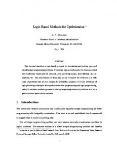
where a, b are the inputs, z 1 , z 2 are the outputs, r i the present states, and R i the next state variables. Our objective is to find an implementation of the circuit with minimum cycle time. Assume, for simplicity, the unit delay model. The network, when mapped directly onto basic 2-input logic gates, results in the circuit shown in Figure 1(a). The longest delay in the combinational logic, and hence cycle-time of the circuit is equal to 3 gate delays. The circuit after retiming, shown in Figure 1(b), has a delay of 2 gates. This solution (verified by SIS) can be obtained by forward retiming across gate g 1 . It can be shown that classical retiming cannot reduce the delay of the circuit any further. We now show that it is possible to obtain a circuit by manipulating directly its functional specification, with a delay of just 1 logic gate. Consider again the set of Eq. (1) specifying the circuit. A careful observation of equation z 2 5 b ~ r 1 r 2 1 r 3 ! suggests that the subexpression ~ r 1 r 2 1 r 3 ! , ACM Transactions on Design Automation of Electronic Systems, Vol. 5, No. 3, July 2000.
Factorization for Sequential Logic Optimization
g1
g1
b
b z2
z2 g5
z1
g5
g3
r2
377
r1
q
r1
•
g3 z1
g4
r3
a
a) Fig. 1.
g4 r3
a
b)
Retiming of an optimized circuit. (a) Original circuit; (b) retimed circuit.
which depends solely on register variables, can be factored out and subsequently retimed across. This retiming introduces a new register variable r 4 5 r 1 r 2 1 r 3 in the expression for z 2 , so that
z2 5 br4, R4 5 R1R2 1 R3 5 r1r2~a 1 r3! 1 r1 5 r1.
(2)
Here R i is the input to the register and r i is its output, a register variable. Now the modified circuit equations are
R1 5 r1r2, R2 5 a 1 r3, R3 5 r1, R4 5 r1, z1 5 a 1 r3, z2 5 br4.
(3)
Furthermore, since R 3 5 R 4 , we can replace each by a new variable R , thus eliminating one register. The final modified circuit equations are
R1 5 r1r2, R2 5 a 1 r, R 5 r1, z1 5 a 1 r, z2 5 br.
(4)
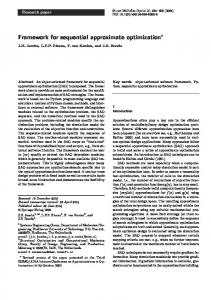
This corresponds to a circuit with only 3 gates and a cycle-time equal to 1 unit (Figure 2(e)). The implications of such a functional modification of the circuit specification deserve some explanation. Basically, such a procedure corresponds to a series of retiming and logic simplification transformations, as depicted structurally in Figure 2. Figure 2(a) shows the original network with the fanout node g 1 duplicated. The reason for this duplication is dictated by a need to the separate path from g 1 to z 2 from other paths, in order to enable later retiming and logic simplification transformations. Figure 2(b) shows the circuit after a series of forward retiming transformations across fanout stems: (1) forward retiming of register r 1 across fanout stems x and y , creating registers r 11 , r 12 and r 13 ; (2) forward retiming of register r 2 across fanout stem w , giving rise to registers r 21 , r 22 ; and (3) forward retiming of register r 3 across fanout stem v , creating registers r 31 , r 32 . To maintain the initial state of the retimed circuit, we need to impose the following constraints (equivalence relations) on register variables: ACM Transactions on Design Automation of Electronic Systems, Vol. 5, No. 3, July 2000.
378
S. Bommu et al.
•
x y
g1
y
g1
b g2
w
z2
g5
g2
w
z1
r31 g4
r3
z1
a
r1
x
b
r21 r4 g2
g5 g3
c)
v
a
z2
r3
b r
g5
r4 g4
g1
b u
r2
z1
r31 z1
r1
g1
g1
g4
r13
b)
r11
w
r32 v
a
a)
y
z2
g5 g3
r22
r2 v
b
r21
r12
g3
g4
x
r11
r1
z2
r2
z1
g5
u
z2
g4
a
a r13
d)
e)
Fig. 2. Interpretation of the functional retiming. (a) Original circuit; (b) circuit after forward retiming of r 1 , r 2 , r 3 across the fanout stems; (c) circuit after retiming across $ g 2 , g 3 % ; (d) circuit after logic simplification of R 4 ; (e) final retime-optimized circuit.
r11 5 r12 5 r13 5 r1, r21 5 r22 5 r2, r31 5 r32 5 r3
(5)
At this point we can perform a forward retiming across a logic block composed of gates g 2 , g 3 (marked by the dotted area in Figure 2(b)) by moving registers r 12 , r 22 , r 32 from their inputs to the output of gate g 3 . Figure 2(c) shows the result of such a retiming, with new register r 4 placed at the output of gate g 3 . Now the expression for R 4 can be simplified (using Eq. (5)):
R4 5 r11r21~a 1 r31! 1 r13 5 r1r2~a 1 r3! 1 r1 5 r1
(6)
It is not surprising that the result is the same as given by Eq. (2). From the structural point of view (which is shown here only for didactic purposes), the above simplification corresponds to logic simplification of the dotted area in Figure 2(c), which leads to the circuit shown in Figure 2(d), described by Eq. (3). This simplification is made possible by recognizing the register equivalence specified by Eq. (5). Finally, registers r 3 , r 4 can be retimed backward across fanout stem u , leading to the optimized circuit in Figure 2(e), described by Eq. (4). As predicted by these equations, the circuit has only three gates and its delay is equal to 1 unit, which is an optimum solution in terms of the delay. Notice that retiming cannot produce the above result because it would not attempt retiming across g 3 , since this would only increase the delay to ACM Transactions on Design Automation of Electronic Systems, Vol. 5, No. 3, July 2000.
Factorization for Sequential Logic Optimization
•
379
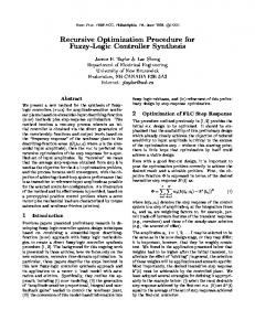
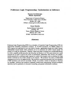
3 units. Also, conventional retiming does not recognize register equivalence, which enables the simplification of the logic across register boundaries. Peripheral retiming [Malik et al. 1991] also could not produce this result because inducing equivalent register relations is not its motive. The same is true for other retiming and resynthesis procedures[De Micheli 1991; Dey et al. 1992; Iqbal et al. 1993; Potkonjak et al. 1993]. In the above example, identifying the retimable subexpression, retiming across those expressions and across the fanout stems, generating the corresponding register equivalence relations, and finally simplifying the underlying logic subject to these relations, makes it possible to optimize the circuit beyond the register boundaries. These steps form the basis of our procedure described in this paper. We now introduce a systematic method to carry out this subexpression extraction, retiming and simplification of underlying logic, all combined in a single synchronous transformation. 3. PRELIMINARIES This section introduces basic terminology necessary to understand our new transformation. A Boolean function F of n variables is a mapping f : B n 3 B , where B 5 $ 0, 1 % . A literal is a Boolean variable or its complement. A cube is defined as a product of literals. The support of a Boolean function is defined as a set of all variables that appear in the function. An expression is said to be cube-free when it cannot be factored by a cube. A kernel of an expression is a cube-free quotient of the expression divided by a cube. Extraction is the process of factoring out a subexpression from one or more logic functions of a network followed by creating a new node for the extracted expression. Collapsing or elimination is the process of (re)expressing a Boolean function representing a node in the logic network in terms of the support variables of its fanin node. A combinational logic network is a network of logic nodes (functions) partitioned into three subsets: primary inputs, primary outputs, and internal nodes. The support of each local function contains variables associated with primary inputs or other internal nodes. Forward retiming is the operation of shifting the registers from the inputs to the output of a node in a Boolean network; backward retiming is the reverse operation. A node in the network can represent an arbitrary Boolean function. It has been shown that such a transformation preserves the sequential behavior of the circuit [Leiserson et al. 1983; Singhal et al. 1995]. Forward and backward retiming transformations are illustrated in Figure 3. A node is said to be forward (backward) retimable if each of its input (output) edges contains a register. A multiple-fanout register is a register that fans out to multiple nodes. Retiming across a fanout stem is the operation of forward retiming of a multiple-fanout register across its fanout stem. The registers produced from this type of retiming have the constraint that their outputs be equal at all times. This imposes an equivalence relation on the fanout registers, and the registers are said to be equivalent. All network transformations and the initial state computation ACM Transactions on Design Automation of Electronic Systems, Vol. 5, No. 3, July 2000.
380
S. Bommu et al.
•
forward retiming
a R1
r1
V f
f
b R2
R1
V
f(a,b) R3
r3
R2
r2 (a)
(b)
backward retiming Fig. 3.
Retiming of a logic node.
must take into account the register equivalence imposed by this equivalence relation. An expression is called a retimable expression if all the variables in its support set are register variables. In this paper we limit our attention to forward retiming involving retimable kernels. Associated with each register is a pair of variables (R i , r i ), where R i is the input to the register and r i is its output, referred to as a register variable, so that r i @ t # 5 R i @ t 2 1 # . The variables r i and R i can also be viewed as inputs and outputs, respectively, of the combinational part of the sequential network, with registers providing feedback paths. 4. THEORY AND ALGORITHMS Traditional retiming across a logic gate (or a node) in a gate-level (or Boolean) network can be extended to a retiming across an arbitrary subexpression (kernel or a cube) of the original functional specification. Such a retiming, combined with the extraction of a suitable expression, forms the basis of our new sequential transformation. We refer to it as the retiming-based factorization (RBF) transformation. This section describes the operations involved in the RBF transformation. 4.1 Retime Extraction Example 2. Consider the sequential logic network represented by the following equations and shown in Figure 5:
O 1 5 i 2 1 r 3i 1 1 r 1r 2i 1 R 1 5 r 1r 2i 2 1 r 3i 2 R 2 5 i 1r 2 R 3 5 i 2 1 i 1r 3 ACM Transactions on Design Automation of Electronic Systems, Vol. 5, No. 3, July 2000.
(7)
Factorization for Sequential Logic Optimization
•
381
forward
V2
f2
V1
f1
V2 R2
R1
r1
r2
f2
f1 f3
R3
V3
r3
f3 V3
backward
Fig. 4.
Retiming across a fanout stem.
In these equations, i i denotes a primary input and r i denotes a register variable (present state variable). O i is a primary output function and R i is a register function (next state function). Consider subexpression k r 5 r 1 r 2 1 r 3 , common to O 1 and R 1 . This subexpression can be extracted from the expressions for O 1 and R 1 and used to create a new node in the network, V x5 . Since all the inputs to k r are register variables, this expression is forward retimable. Forward retiming across V x5 leads to the creation of a new register represented by variables ~ R 4 , r 4 ! . After retiming, the expression for R 4 is then given in terms of register input variables R i , as illustrated in Figure 6. This transformation can be expressed as a new operation, called retimeextraction, which is the basis of our RBF transformation. For a given retimable expression k r , the following steps implement retime-extraction: (1) For every node f i of the network, containing expression k r , substitute the expression with a variable r k . (2) Introduce a new node corresponding to k r expressed in terms of register input variables, R i . Represent it by register function R k . (3) Introduce a new register (R k , r k ). It should be emphasized that whenever the register variables in the support of retimable expression k r fan out to other functions, the retimeextract operation involves implicit retiming across fanout stems. In our example this applies to registers R 2 , R 3 which have multiple fanouts. Consequently, a set of equivalence relations will be imposed on these registers and used in the subsequent logic simplification. On the other hand, if a register involved in the retime-extraction fans out solely to the retimable expression, then it will be rendered redundant by the transformation and can subsequently be removed. In the example, register R 1 fans out only to the retime-extracted expression. Consequently, it can be removed later, along with the associated logic function (see Figures 6, 7, and 8). ACM Transactions on Design Automation of Electronic Systems, Vol. 5, No. 3, July 2000.
382
•
S. Bommu et al.
Vx1
i1
x1=i2 + r3i1 + r1r2i1 i2
O1
Vx2
R1
r1
R2
r2
R3
r3
R1
x2=r1r2i2 + r3i2 Vx3
R2
x3= i1r2
R3
x4=i2 + i1r3 Vx4 Fig. 5.
The original network.
Vx1
i1
x1=i2 + i1r4 i2 R1 R2 R3 R2
r2
R3
r3
Vx2
Vx5 x5=R1R2 + R3
R4
r4
x2=r4i2
O1 R1
Vx3 x3= i1r2 x4=i2 + i1r3
R2
R3
Vx4 Fig. 6.
Retime-extraction of ~ r 1 r 2 1 r 3 ! .
4.2 Collapsing and Simplification In the next step, the node represented by a new variable R k is collapsed into its fanin nodes, as shown in Figure 7. The resulting expression is then simplified. Notice the implicit duplication of logic, necessary to perform the collapsing and simplification. This ensures that the functionality of the rest of the network remains unchanged. In our case, logic for R 1 , R 2 , R 3 is duplicated (see the area marked by the dotted line). The simplification is possible, in effect, due to register equivalence imposed on fanout registers. For simplicity, in all the figures we use the same variable name for each of the registers obtained after retiming across a fanout. In our case the collapsing and simplification leads to the following expression:
R4 5 R1R2 1 R3 5 ~r4i2!~i1r2! 1 ~i2 1 i1r3! 5 i2 1 i1r3 ACM Transactions on Design Automation of Electronic Systems, Vol. 5, No. 3, July 2000.
(8)
Factorization for Sequential Logic Optimization
x1=i2 + i1r4
Vx2 i2
Vx2
R1 Vx5
Vx3 x3= i1r2
R2
x5=R1R2 + R3
x2=r4i2 R4
r4
R3 r2
x4=i2 + i1r3
Vx4 R3
Fig. 7.
r3
O1 R1
Vx3 x3= i1r2
R2
x4=i2 + i1r3
383
Vx1
i1
x2=r4i2
•
R2
R3
Vx4
Collapsing of R 4 into its fanin nodes.
The simplified Boolean expression for R k is also referred to as a retimeexpression RE ~ k r ! . It can be calculated for every retimable cube or kernel k r using the above procedure. The computation of RE ~ k r ! is central to the RBF transformation. In our example, the simplified expressions associated with node V x5 5 ~ i 2 1 i 1 r 3 ! is identical to that of V x4 ; subsequently, R 4 can be derived directly from V x4 , as shown in Figure 8(a). Furthermore, since the register functions R 3 , R 4 are identical, the two registers could be merged into one, provided that their initial states are identical, that is, r 03 5 r 04 . Whether this is possible or not, depends on the initial conditions imposed on the network; the issue of initial state computation is discussed in the next section. Finally, notice that register function R 1 is not used. This is because the register disappeared as a result of retime extraction across ~ r 1 r 2 1 r 3 ! . Therefore, the combinational logic function associated with the register function can be deleted. The resulting network is shown in Figure 8(b). This network is a direct result of our RBF transformation. The retime-extraction, collapsing and simplification transformations are performed implicitly through the computation of the retime-expression. 4.3 Initial State Computation The correctness of the retime-extraction transformation is not complete unless the initial conditions of the register, introduced by this transformation, are resolved. The initial state computation upon forward retiming across an arbitrary logic expression, as formally given in Touati and Brayton [1993], is straightforward. Implicit retiming across fanout stems requires additional conditions on the register value, namely the register equivalence mentioned above. Let r 0i be the initial value of a register ~ R i , r i ! . For a retimable expression k r ~ r 1 , r 2 , ..., r n ! , the initial value of the register (R k , r k ), added by the retime-extraction, is given by r 0k 5 k r ~ r 01 , r 02 , ..., r 0n ! . For the example above, with retimable expression k r 5 r 1 r 2 1 r 3 , the initial value of register (R 4 , r 4 ) is then given by r 04 5 r 01 r 02 1 r 03 . The analysis of this expression reveals that we cannot blindly replace registers R 3 , R 4 by a single register, unless either r 01 or r 02 can be guaranteed to be 0. ACM Transactions on Design Automation of Electronic Systems, Vol. 5, No. 3, July 2000.
384
•
S. Bommu et al. Vx1
i1
i1
x1=i2 + i1r4 i2 R2
Vx2
Vx3 R3
R4
r3
r4
R2
r2
R3
r3
R2
x3= i1r2
R4
O1
Vx3 x3= i1r2
x4=i2 + i1r3 Vx4
R3
x4=i2 + i1r3
R2
R3 R4
r4
R4
Vx4
Fig. 8.
i2
R1
x2=r4i2
r2
Vx1 x1=i2 + i1r4
O1
(a) Network after simplification; (b) final network after removal of redundant logic.
4.4 Comparison with Extraction and Gate-Level Retiming The following example illustrates that the RBF transformation can lead to circuit optimization (both in terms of delay and logic area), which is not possible with conventional multi-level synthesis based on extraction of combinational expression, or with gate-level retiming alone. Example 3 (delay minimization). Example 2.
Consider again the logic network of
O 1 5 ~ r 1r 2 1 r 3! i 1 1 i 2 R 1 5 ~ r 1r 2 1 r 3! i 2 R 2 5 i 1r 2 R 3 5 i 2 1 i 1r 3 Compare RBF transformation, applied to retimable kernel k r 5 ~ r 1 r 2 1 r 3 ! , with regular extraction of k r and retiming; see Figure 9.
5. RBF SYNTHESIS Retiming-based factorization, when applied systematically, can lead to a network optimization which is not possible with any of the prevailing synthesis techniques. We refer to the systematic application of RBF over the entire network as an RBF synthesis. In this section, we first introduce a framework within which the RBF technique can be integrated with a regular extraction transformation so that the cycle-time of a logic network is optimized. We then review the issue of technology-independent delay models and their application to RBF synthesis. 5.1 Delay Optimization Procedure A general delay model independent procedure for optimizing a logic network using RBF synthesis is shown below. The procedure for RBF-based ACM Transactions on Design Automation of Electronic Systems, Vol. 5, No. 3, July 2000.
Factorization for Sequential Logic Optimization
•
385
Fig. 9. Comparison of retiming-based factorization with extraction and retiming; feedback loops R i 3 r i are omitted for simplicity.
optimization involves the computation of retimable subexpressions of the Boolean logic associated with each node of the network. The candidate subexpressions are then extracted or retime-extracted, depending on the relative gain of these transformations, resulting in an optimized logic network. The following procedure gives the steps involved in network optimization using RBF synthesis. (1) Select a set of candidate subexpressions to be extracted. (2) For each candidate subexpression, do the following: (a) Check if it is retimable. (b) If retimable, estimate the delay gain of retime-extraction (d r ) and regular extraction (d x ). It should be emphasized that the gain d r for the retime-expression k r is based on all the transformations involved: retime-extraction, collapsing and simplification. (c) If retime-extraction is estimated to give better gain, perform retime-extraction. Otherwise, perform regular extraction. In step (1), computing the set of subexpressions assumes the availability of the Boolean logic of individual nodes of the network in sum-of-products (SOP) form. The number of extractable common subexpressions which can be identified is maximized if the nodes of the unoptimized network are ACM Transactions on Design Automation of Electronic Systems, Vol. 5, No. 3, July 2000.
386
•
S. Bommu et al.
collapsed until their support variables are all primary inputs. This procedure, though effective, is impractical for large designs. In general, the fanin of a node is collapsed into that node recursively until the SOP expression of individual nodes reaches a predefined limit (this is implemented as the eliminate command in SIS). The order of extraction of the subexpressions also has an impact on the extent of optimization possible. For example, the extraction of a nonretimable kernel could preclude the extraction of some other retimable kernels. Keeping this point in mind, the implementation of RBF synthesis algorithm should provide the means by which the order of extraction of the subexpressions can be controlled. In our implementation, options are provided to favor the extraction of retimable subexpressions before extracting nonretimable subexpressions. This provides a means of controlling the order of subexpression extraction to maximize the gain of RBF synthesis. The quality of the results obtained with RBF synthesis clearly depends on the gain estimation and the delay models considered and the heuristics used to accept a given kernel. In other words, the criteria used to assign the values of d x and d r for a given subexpression ultimately determine the effectiveness of RBF synthesis. The remainder of this section is devoted to the issue of delay modeling, and the heuristics used in determining the gain of retime-extraction over regular extraction. 5.2 Delay Models, Review Delay modeling of an unmapped logic network is complicated by the lack of a priori knowledge of delay characteristics of the logic gates. The best model is that which can best predict the technology mapping accurately and efficiently. We first introduce some basic concepts required as a background for delay modeling. The definitions are given here in terms of logic gates, but the principles can be applied to an unmapped Boolean network by extension. The delay of a multi-level logic network consists of two components, node delay and network delay. Node delay refers to the delay of the individual nodes of the network, possibly as a function of output loading, while the network delay represents the maximum delay among all the input-output paths in the network. Node delay. The delay of a node can be expressed as
d 5 dI 1 sf
(9)
d I is the intrinsic delay of the node; it is defined as the difference between the time when an input signal reaches half of its voltage swing and the time when the rising/falling output signal reaches half of its voltage swing. The product sf represents the transition delay of the node, where s is a slew rate, defined as the delay per unit fanout of the node, and f is the fanout factor. Path delays. Path delay is the total delay incurred by a signal as it propagates from one point in the network to another. The total delay ACM Transactions on Design Automation of Electronic Systems, Vol. 5, No. 3, July 2000.
Factorization for Sequential Logic Optimization
•
387
through a path is the sum of the intrinsic and transition delays along the path. Arrival time. The arrival time at a given point in the circuit is the earliest time at which the signal is available at that point. The arrival time of the node is computed by forward traversal of the network, starting at the primary inputs by adding node delay to the arrival time of the latest arriving input. Required time. The required time at a node in the network is the latest time at which the signal must be available at that node. The required time is computed by a backward traversal of the network, starting at the primary outputs by subtracting node delay from the required time of its output. Slack. Slack is the difference between the required time and arrival time at a given node. A path with negative or zero slack is called a critical path. We now review the delay models which differ in the kind of assumptions made about the node and the network delays. 5.2.1 Unit-Delay Model. The most general method of estimating the delay in an unmapped Boolean network is based on the unit-delay model. It models the delay of a node as a single unit and ignores the effect of output loading on its delay. Although simplistic, the model gives a good approximation for networks where the nodes are roughly of the same size. 5.2.2 Augmented Unit-Delay Model. This model, also called the fanout delay model, is an extension to the unit-delay model. A single unit delay is assigned to each node as before. However, the effect of output load on the delay is taken into account by assigning a non-zero slew rate (Eq. (13)). The slew rate is typically fixed, and equal to a fraction of the internal node delay, d I (assumed to be 0.2 in SIS). 5.2.3 Mapped Delay Model. Unlike the previous models, this model can only be used on a mapped network, using the delay information stored in the cell library. It is similar to the augmented unit delay model, except that internal delay and the slew rate information are specified in the precharacterized library of logic cells. In order to compute the delay of a path, delay trace is performed using the delay information stored in the library. 5.2.4 Approximate Timing Delay Models. In this approach, the delay of each node is estimated using an approximate delay model (discussed below); this estimated delay is used to compute the overall network delay. The arrival time at each node is computed by a forward traversal of the network. The arrival times at the primary outputs give a good estimate of the overall network delay. Further information about the critical nodes in the network can be obtained by a backward traversal of the network, enabling the computation of the required time and slack at each node. The nodes with zero/negative slack represent a critical path in the network. The approximate delay models give a better estimate of the overall network delay than the unit delay or fanout delay models; however, they ACM Transactions on Design Automation of Electronic Systems, Vol. 5, No. 3, July 2000.
388
•
S. Bommu et al.
involve graph traversal algorithms which makes them inherently less efficient. Furthermore, the accuracy of the delay model depends on the ability to correctly estimate the delay of the individual nodes of the network. In the remainder of this section we shall present some of the techniques used to estimate the delay of an individual node of an unmapped network. Wallace model. The delay model introduced by Wallace et al. [1990] estimates the complexity of a node with a formula based on the decomposition of the logic expression of the node onto a minimum-height tree. An unmapped node in the network is stored in sum-of-products form. From this representation the following formula gives a pessimistic estimate for the arrival time at the output of the node:
d 5 DGlog2N 1 DGlog2Fmax 1 Ai 1 sF
(10)
D G is the delay of a two-input gate, N is the number of product terms, F max is the fanin of the product term with the largest number of literals, A i is the arrival time of the latest arriving input, s is an estimate of the average slew rate for the target library, and F is the fanout number of the node. This model offers an upper bound on the mapped delay. The first term can be viewed as the ‘breadth’ of the node and the second term as its ‘depth.’ The third term gives a rough estimate of the input arrival times, and the fourth term is the transition delay. TDC model. Probably the most accurate delay prediction strategy for technology-independent logic optimization is the timing driven cofactor (TDC) model of Gutwin et al. [1992]. It is based on a fast decomposition of nodes using BDDs. The framework for calculating the unbalanced delay of a node is as follows. The idea is to estimate closely what a mapping procedure will do. According to Gutwin et al. [1992], mapping procedures are generally socialist in that they aim to place most of the logic in the paths of the earliest arriving signals, and take the logic out of the later arriving signals. In this way, the overall delay over all paths is minimized. Figure 10 illustrates the procedure: (1) The input signals are partitioned into groups G i based on their relative arrival times. (2) The equivalent network of F i ’s is derived by performing the cofactor of the node function F over the group G i . (3) The balanced delay of each of the functional blocks F i is calculated. (4) The total delay for F is given as the critical path through the resulting network. 5.3 Delay Models Applied to Retiming-Based Factorization This section gives some theoretical results on the reduction of cycle-time resulting from the application of retiming-based factorization. First, some ACM Transactions on Design Automation of Electronic Systems, Vol. 5, No. 3, July 2000.
Factorization for Sequential Logic Optimization
•
389
Functional Blocks Fi+1
Gi+1
Fi Gi Fi-1
f
Gi-1 Fig. 10.
Performance optimized logic network.
additional notation is presented that will be useful in describing these results. 5.3.1 Notation ● f ~ V ! is the Boolean function associated with node V . ● fanin ~ V ! is the set of nodes which fan in to node V . ● fanout PO ~ V ! represents the set of primary outputs or input register variables which are in transitive fanin of node V . ● arrival 2 time new ~ V ! is the arrival time at the output of node V . It is computed after the corresponding transformation (retime-extraction or regular extraction) has taken place. ● delay ~ N ! is the overall delay of the network prior to applying the extraction or retime-extraction transformation. ● delay new ~ N ! is the overall delay of the network after applying the extraction or retime-extraction transformation. ● V ret ~ k r ! is a node associated with retimable kernel k r . In this case the registers are simply forward retimed across the kernel and no collapsing is performed. ● R is a set of input register variables $ R i % in the network. 5.3.2 Potential Cycle-Time Reduction. The unit-delay model will be used here to illustrate how retiming-based factorization can reduce the network cycle-time. THEOREM 1. If the delay of a network is estimated using a unit-delay model, retiming-based factorization of a retimable subexpression k r does not increase the delay of a sequential logic network. PROOF. Consider an internal node V in the network. By the definition of arrival time:
arrival2time~V ! 5 Node2Delay~V ! 1 max arrival2time~a!
(11)
a[fanin~V !
ACM Transactions on Design Automation of Electronic Systems, Vol. 5, No. 3, July 2000.
390
S. Bommu et al.
•
Since we are using a unit delay model,
max arrival2time~a! 5 arrival2time~V!21
(12)
a[fanin~V !
Let V RE be the new internal node introduced by retime extraction of k r ~ r 1 , r 2 , ..r n ! . The retime expression RE ~ k r ! is then defined as RE ~ k r ! 5 k r ~ R 1 , R 2 , ..., R n ! .1 where R i are input register variables of the registers involved in the retiming of k r ~ r 1 , r 2 , ..r n ! . Then,
arrival2time~VRE! 5 1 1 max arrival2time~a!
(13)
a[fanin~Ri!
Using Eq. (12), the above equation becomes
arrival2time~VRE! 5 5
max Ri[fanin~Vret~kr!!
max Ri[fanin~Vret~kr!!
~arrival2time~Ri!21!11 ~arrival2time~Ri!!
(14)
But since $ R i [ fanin ~ V ret ~ k r ! !% , R , we have
arrival2time~VRE! # max arrival2time~Ri!
(15)
arrival2time~VRE! # delay~N !
(16)
Ri[R
Therefore,
and hence the overall delay of the network will not increase under the unit delay model. e The above theorem shows that retime-extraction of a kernel does not increase the topological longest path under the unit-delay model. The following corollary shows that, contrary to the retime-extraction, regular extraction can increase the overall delay of the network under the unit delay model. Observation 1. If the delay of a network is estimated using a unit-delay model, the regular extraction of a subexpression k r may increase the delay of a sequential logic network under certain condition. PROOF. Consider kernel k extracted from a node V k . Assuming the unit delay model, we have
Recall that, according to our notation, r i @ t # 5 R i @ t 2 1 # , so that k r ~ R 1 , R 2 , ..., R n ! represents a function that is expressed in variables from a previous time frame; refer to Figure 6 for clarification. 1
ACM Transactions on Design Automation of Electronic Systems, Vol. 5, No. 3, July 2000.
Factorization for Sequential Logic Optimization
•
arrival2timenew~PO! 5 arrival2time~PO!11, @PO [ fanoutPO~Vk!,
391
(17)
where PO is a set of primary outputs or register input variables. Then, if the following condition holds,
delay~N ! 5 arrival2time~PO ? PO [ fanoutPO~Vk!!
(18)
the cycle-time of the network increases, i.e.,
delaynew~N ! 5 delay~N ! 1 1
(19)
e In conclusion, under the unit delay model retime-extraction always results in lower delay than regular extraction. It can also be shown that under an augmented (fanout) unit delay model, the retime-extraction may— under certain conditions—adversely affect the network delay. This is due to the fanout increase of the internal nodes and the subsequent changes in the capacitive loading of the nodes affected by retime extraction [O’Neill 1997]. It may happen, for example, that a node on a critical path fans out to a newly created node V ~ k r ! , causing delay increase along that path (see node V 1 in Figure 12). Detailed analysis of this case is given in O’Neill [1997]. This problem can be readily identified by considering an augmented delay model which takes into consideration the fanout factor. The issue of accurate delay gain estimation and targeting critical delay regions will be discussed in the next section. 5.3.3 RBF Based on the Unit Delay Model. In this model, the decision whether to use retime-extraction or regular extraction is based on the estimate of the network delay using the unit-delay model. From Theorem 1 and Observation 1 of Section 5, it is clear that retime-extraction can do no worse than regular extraction. However, indiscriminate application of retime-extraction could actually degrade the network performance. To understand the reason for this it is important to understand the limitations of the unit-delay model. Network delay estimation using a unit-delay model is only justifiable if the size (complexity) of the individual nodes of the network is approximately equal. Transformations to a logic network which do not alter the relative complexities of the nodes of a network can therefore be expected to produce good results even when they are based on a unit-delay model. The preceding discussion provides the intuition for the heuristic used in retimeextraction transformation based on a unit delay model. According to this heuristic, retime-extraction of a subexpression is considered preferable to a regular extraction if the complexity of the new node added to the network by retime-extraction is no greater than the complexity of the node(s) from which the subexpression has been extracted. The complexity of the individual nodes is measured by the number of literals in the SOP form of the Boolean function of the node. ACM Transactions on Design Automation of Electronic Systems, Vol. 5, No. 3, July 2000.
392
•
S. Bommu et al.
V1
V2
V3
kr RE( k r )
r k
Candidate node Fig. 11.
Delay gain estimation based on literal count.
Figure 11 illustrates the idea of cost estimation based on a simple literal count. It is important to note that the two candidate nodes, k r and RE ~ k r ! , are not yet part of the network. The two transformations are being evaluated as to which produces the better gain. The gains are computed as follows: d x , associated with k r (for standard extraction), and d r , associated with RE ~ k r ! (for retime-extraction). In the figure
dx 5 max$lit2count~V1!, lit2count~V2!, lit2count~V3!% dr 5 lit2count~RE~kr!! Retime-extraction (which results in the addition of node RE ~ k r ! ) is performed if d r , d x . Note that the literal counts of nodes V1, V2, V3 are computed before the extraction or retime-extraction; these counts, therefore, include the literals of k r . 5.3.4 RBF Based on Appproximate Timing Delay Models. Extraction based on the unit-delay model, described in the previous section, might not work well for all designs. One of the primary limitations of this approach is the lack of detailed delay information. In this section retime-extraction is reevaluated using the approximate timing delay model described in Section 5.2.4. The extraction (or retime-extraction) of a subexpression modifies the topology of the network. Since the timing information of the network changes with any modifications made to the network, extraction of a subexpression might involve recomputing the arrival time information of the network. If timing data for all the nodes of the network need to be modified after every extraction, the algorithm will be inefficient, and, for all practical purposes, ineffective. Fortunately, as explained in Section 5.3.5, the extraction of a subexpression affects the timing of only a subset of the nodes of the network; efficient updating of the timing information is central to the use of this timing model for the RBF synthesis. The ACM Transactions on Design Automation of Electronic Systems, Vol. 5, No. 3, July 2000.
Factorization for Sequential Logic Optimization
N
I
N
I
O
O
xi k r
r
393
•
V2
V
V R
r
R V1 I r k
r
x
x RE(k r )
k
Rk
Fig. 12. Comparison of arrival times: (a) after regular extraction; (b) after retiming-based factorization.
remainder of this section describes the criteria used in making the comparison between the retime-extraction and regular extraction. It also discusses ways to efficiently update the timing information after extracting a subexpression. The relative merits of the regular extraction and the retime-extraction transformations are evaluated by comparing the latest arrival time originating at the regularly extracted node, with the arrival time at the output of the retime-extracted node. This involves forward traversal from the node from which a candidate expression k r has been extracted, and a backward traversal from the retime-extracted node. That is, max $ arrival 2 time ~ x i !% over all output nodes o i of the network is compared with arrivalt 2 ime ~ x k ! , where x k is the output of the retimed expression RE ~ k r ! , as illustrated in Figure 12. 5.3.5 Estimation Procedure Using Incremental Update Method. This section discusses the implementation of the gain estimation procedure based on the TDC model introduced in Section 5.2.4. In order to reduce computation time, the gain estimation procedure uses an incremental update method, illustrated in Figure 13. The numbers at the node inputs refer to the arrival times, and those at the output of the node represent the arrival time change, before and after the application of the retime-extraction or extraction transformation. The value of D refers to the change in arrival time as a result of an extraction or retime-extraction of a subexpression from V 1 . The bold edges indicate the parts of the network affected by the extraction. Consider the following two cases. (1) For path V 1 3 V 7 , the change in arrival time ripples through to the output, and causes the output delay to change from 6 to 7 units. This is because the node inputs that are on the path originating at V 1 are the latest arriving inputs to the nodes V 5 , V 6 and V 7 . (2) In the case of path V 1 3 V 4 , the change in arrival times stops at ACM Transactions on Design Automation of Electronic Systems, Vol. 5, No. 3, July 2000.
394
•
S. Bommu et al. 6
6
5
3 V V2 V1 3
3
4
5
8
V4 =0
=0
=1
4
7
=0
=1 2
V
5
=1 3
4
5 V6 =1
5
6
V
7
4
=1
6
7
=1
4 Fig. 13.
Example showing incremental update method (unit delay model).
node V 3 , because the output of V 2 is no longer the latest arriving input to V 3 . This observation is the basis for the incremental update method: one needs to recompute the delay of only those nodes which are affected by the current transformation. Furthermore, the amount by which the delay along the affected paths is modified is derived from the output arrival time of the node from which the kernel under consideration was retime-extracted. The incremental update procedure has been applied to the TDC delay model in our RBF synthesis. By using this method the computationallyintensive delay-trace operation of SIS needs to be used only once at the start of the transformation. Thereafter, only local updates need to be computed as described for the unit-delay model above. 6. IMPLEMENTATION AND EXPERIMENTAL RESULTS The RBF transformation has been implemented within the SIS framework. In addition to the standard SIS functions, such as kernel and cube extraction, new routines related specifically to RBF have been added, such as retime-extraction, cost estimation, incremental delay update, etc. The generation of common subexpressions was implemented with the rectangle intersection algorithm of SIS. In the first version of the program the RBF transformation has been limited to forward retiming, and retime-extraction limited to kernels. Only those kernels whose value exceeds the user-defined threshold are selected. Retimable kernels are then identified as candidates for retime-extraction. For each of the selected retimable kernels, retimeextraction is compared with the regular extraction using the gain estimation technique. A new command, called retime kernel extract (rkx) was created to perform retime-extraction of a kernel, collapsing, and simplification. This forms a basic transformation of RBF synthesis. Several experiments were conducted, each employing different delay models and gain estimation techniques discussed in Section 5. These include (1) technique based on unit-delay model; (2) models using approxiACM Transactions on Design Automation of Electronic Systems, Vol. 5, No. 3, July 2000.
Factorization for Sequential Logic Optimization
•
395
mate formula; and (3) the TDC delay. We tested our technique on a number of sequential circuits from the ISCAS’91 benchmark set. Results are reported only for those circuits which contained retimable kernels. The circuits were input as logic networks in blif format, while its local functions (nodes) were collapsed into SOP form. Each circuit was then optimized using RBF synthesis and independently synthesized with standard multilevel optimization of SIS. Finally, all the circuits were mapped onto the standard SIS lib2.genlib library. The script used for RBF synthesis is similar to script rugged of SIS, with the gkx command being replaced by the rkx command of RBF synthesis. The final delays reported below were computed using the mapped delay model. The general structure of the scripts used in our experiments is given below:
script.rkx script.gkx sweep sweep collapse or eliminate ,threshold. collapse or eliminate ,threshold. simplify simplify rkx ,options. gkx ,options. resub -a resub -a sweep sweep simplify simplify Table I reports the results based on the unit-delay model. The table compares clock-cycle delays, number of registers, and total area overhead of the mapped circuits obtained by the two flows. The CPU time (in seconds) required for both scripts is also reported (for Spark 20). Table II shows the results obtained using the TDC model with the incremental update method discussed in Section 5. Even though the initial implementation of RBF synthesis used a simplistic figure of merit based on literal count, most of the circuits synthesized with this technique showed a significant reduction in delay. This is not unexpected, since our technique performs retiming implicitly as part of multi-level logic optimization. It confirms our conviction that this new optimization technique can be used as an efficient delay minimization tool. The experimental results reveal somewhat significant area increase due to additional registers introduced by retiming. With the decreasing line widths and feature sizes, the delay of the larger circuits may become dominated by global interconnect delay than by gate delays. In this situation the increase in area may complicate the routing and possibly degrade performance. However, this degradation is already considered in the mapped delay model by accounting for the increased fanout on the intermediate gates and/or primary inputs. If needed, the resulting increase in load capacitance can be effectively handled by appropriate gate and driver resizing. Furthermore, the increase in the complexity or density of the final routing may not necessarily translate into the increased wiring ACM Transactions on Design Automation of Electronic Systems, Vol. 5, No. 3, July 2000.
396
•
S. Bommu et al.
Table I.
rkx vs gkx using Unit-Delay Model; Comparison of Mapped Circuits
Ckt
rkx Area
s298 s344 s444 s526 s400 s9234 s5378 s510 s15850 s1488 s382
167040 198592 223648 228288 266800 1156752 1316832 245920 3912912 629648 329904
Clk
CPU
Area
Clk
202768 229216 218080 224112 330368 1186448 1307552 245920 3814080 609232 260768
Reg
CPU Area 15 6 10 10 26 5 2 10 3 4 53
Clk
Reg
CPU
212 221 227 226 215 217 24 213 24 7 223
79 13 14 19 33 9 17 33 7 117 57
28 96 11 15 48 15 14 5 3 64 68
rkx vs gkx using TDC Model; Comparison of Mapped Circuits
rkx- TDC Area
s298 s344 s444 s526 s400 s9234 s5378 s510 s15850 s1488 s382
Reg
% increase
9.59 25 20.3 145232 10.95 14 15.9 13.50 17 40.5 187456 17.06 15 20.7 9.51 24 25.6 203232 13.09 21 23.1 10.10 25 26.2 208336 13.64 21 22.9 11.05 28 36 211120 12.95 21 24.3 31.90 147 62.6 1101536 38.28 135 54.4 25.29 189 58 1286672 26.31 162 56.3 24.49 8 9 223184 28.20 6 7.9 104.1 538 276.6 3802480 108.23 504 269.4 42.72 13 65.4 607840 39.67 6 39.7 10.63 33 39.8 215760 13.82 21 23.7
Table II. Ckt
gkx
Clk
Reg
gkx CPU
Area
Clk
% increase Reg
CPU Area
8.91 17 44.5 145232 10.95 14 15.9 12.59 17 42.0 187456 17.06 15 20.7 10.36 23 43.3 203232 13.09 21 23.1 12.0 22 92.4 208336 13.64 21 22.9 9.49 27 46.3 211120 12.95 21 24.3 32.94 149 146.8 1101536 38.28 135 54.4 25.33 192 126.8 1286672 26.31 162 56.3 24.49 8 29.3 223184 28.20 6 7.9 108.42 505 4148.5 3802480 108.23 504 269.4 39.03 6 1974.1 607840 39.67 6 39.7 11.33 25 84.7 215760 13.82 21 23.7
40 22 7 8 57 8 2 10 0 0 21
Clk
Reg
CPU
219 226 221 212 227 214 24 213 0 22 218
21 13 10 5 29 10 19 33 0 0 19
280 203 187 403 191 270 225 371 1540 4972 357
length, which remains the best approximation of the interconnect delay. The average interconnect length, and its delay may remain unaffected. Finally, for the size of the circuits to which this technique is applicable (typically control circuits), the delay due to interconnect may not matter that much. Performance of control circuits remains, at least for now, largely unaffected by the secondary effects of deep submicron technology.
7. CONCLUSIONS AND FUTURE WORK Prevailing approaches to sequential optimization involve the application of combinational logic optimization and retiming techniques in isolation. Noting the drawbacks of such a scheme, we proposed an alternative approach which integrates retiming with combinational optimization techniques. Specifically, we demonstrated the advantages of integrating retiming with common kernel extraction and introduced a new retiming-based factorization (RBF) technique. ACM Transactions on Design Automation of Electronic Systems, Vol. 5, No. 3, July 2000.
Factorization for Sequential Logic Optimization
•
397
Experimental results confirm our conviction of the potential application of the presented approach to clock cycle minimization. One can notice that the results do not seem to depend much on the accuracy of the delay estimation method used. This suggests the limitation of the entire synthesis process, which is inherently greedy; a transformation is applied to the network if the estimated gain exceeds a predefined threshold, without regard to the consequences of that transformation on the subsequent transformations applied to other nodes. An alternative approach would be to consider a subset of retimable expressions and estimate their collective gain, instead of dealing with one expression at a time. Future research in this area should investigate such alternatives. While the presented RBF technique targeted the cycle time minimization, we believe that its application is not limited to delay optimization. It seems also applicable to other metrics for which reliable and efficient gain estimation methods are available; these include logic area (possibly under delay constraint), power (as addressed in system POSE [Iman 1995]), testability, and reliability. REFERENCES CHAKRADHAR, S. T., DEY, S., POTKONJAK, M., AND ROTHWEILER, S. G. 1993. Sequential circuit delay optimization using global path delays. In Proceedings of the 30th ACM/IEEE International Conference on Design Automation (DAC ’93, Dallas, TX, June 14 –18), A. E. Dunlop, Ed. ACM Press, New York, NY, 483– 489. CHANDRAKASAN, A. P., POTKONJAK, M., MEHRA, R., RABEY, J., AND BRODERSON, R. W. 1995. Optimizing power using transformations. IEEE Trans. Comput.-Aided Des. Integr. Circuits 14, 1 (Jan. 1995), 12–31. DE MICHELI, G. 1991. Synchronous logic synthesis: Algorithms for cycle-time optimization. IEEE Trans. Comput.-Aided Des. Integr. Circuits Syst. 10, 1 (Jan. 1991), 63–73. DE MICHELI, G. 1994. Synthesis and Optimization of Digital Circuits. McGraw-Hill, Inc., New York, NY. DEY, S., POTKONJAK, M., AND ROTHWEILER, S. G. 1992. Performance optimization of sequential circuits by eliminating retiming bottlenecks. In Proceedings of the 1992 IEEE/ACM International Conference on Computer-Aided Design (ICCAD ’92, Santa Clara, CA, Nov. 8 –12), L. Trevillyan, Ed. IEEE Computer Society Press, Los Alamitos, CA, 504 –509. GUTWIN, P., MCGEER, P., AND BRAYTON, R. 1992. Delay rrediction for technology-independent logic equations. In Proceedings of the IEEE International Conference on Computer Design, IEEE Computer Society Press, Los Alamitos, CA, 468 – 471. HACHTEL, G. D., HERMIDA, M., PARDO, A., PONCINO, M., AND SOMENZI, F. 1994. Re-encoding sequential circuits to reduce power dissipation. In Proceedings of the 1994 IEEE/ACM International Conference on Computer-Aided Design (ICCAD ’94, San Jose, CA, Nov. 6 –10, 1994), J. A. G. Jess and R. Rudell, Eds. IEEE Computer Society Press, Los Alamitos, CA, 70 –73. HASSOUN, S. AND EBELING, C. 1996. Architectural retiming: Pipelining latency-constrained circuits. In Proceedings of the 33rd Annual Conference on Design Automation (DAC ’96, Las Vegas, NV, June 3–7), T. P. Pennino and E. J. Yoffa, Eds. ACM Press, New York, NY, 708 –713. IMAN, S. AND PEDRAM, M. 1995. Logic extraction and factorization for low power. In Proceedings of the 32nd ACM/IEEE Conference on Design Automation (DAC ’95, San Francisco, CA, June 12–16, 1995), B. T. Preas, Ed. ACM Press, New York, NY, 248 –253. IQBAL, Z., POTKONJAK, M., DEY, S., AND PARKER, A. 1993. Critical path minimization using retiming and algebraic speed-up. In Proceedings of the 30th ACM/IEEE International ACM Transactions on Design Automation of Electronic Systems, Vol. 5, No. 3, July 2000.
398
•
S. Bommu et al.
Conference on Design Automation (DAC ’93, Dallas, TX, June 14 –18), A. E. Dunlop, Ed. ACM Press, New York, NY, 573–577. LALGUDI, K. N. AND PAPAEFTHYMIOU, M. C. 1995. DELAY: An efficient tool for retiming with realistic delay modeling. In Proceedings of the 32nd ACM/IEEE Conference on Design Automation (DAC ’95, San Francisco, CA, June 12–16, 1995), B. T. Preas, Ed. ACM Press, New York, NY, 304 –309. LEISERSON, C., ROSE, F., AND SAXE, J. 1983. Optimizing synchronous circuitry by retiming. In Proceedings of the Third Caltech Conference on VLSI, 87–116. LIN, B. 1993. Restructuring of synchronous logic circuits. In Proceedings of the 1993 European Conference on Design Automation (EDAC ’93 EURO-ASIC, Feb.), 205–209. MALIK, S., SENTOVICH, E., BRAYTON, R., AND SANGIOVANNI-VINCENTELLI, A. 1991. Retiming and resynthesis: Optimizing sequential networks with combinational techniques. IEEE Trans. Comput.-Aided Des. Integr. Circuits Syst. 10, 1 (Jan. 1991), 74 – 84. MONTEIRO, J., DEVADAS, S., AND GHOSH, A. 1993. Retiming sequential circuits for low power. In Proceedings of the International Conference on Computer-Aided Design (ICCAD ’93, Santa Clara, CA, Nov. 7–11), M. Lightner and J. A. G. Jess, Eds. IEEE Computer Society Press, Los Alamitos, CA, 398 – 402. O’NEILL, N. 1997. Sequential logic synthesis based on retiming-based factorization. Master’s Thesis. University of Massachusetts Press, Amherst, MA. POTKONJAK, M., DEY, S., IQBAL, Z., AND PARKER, A. 1993. High performance embedded system optimization using algebraic and generalized retiming techniques. In Proceedings of the IEEE International Conference on Computer Design, IEEE Computer Society Press, Los Alamitos, CA, 498 –504. SHENOY, N. AND RUDELL, R. 1994. Efficient implementation of retiming. In Proceedings of the 1994 IEEE/ACM International Conference on Computer-Aided Design (ICCAD ’94, San Jose, CA, Nov. 6 –10, 1994), J. A. G. Jess and R. Rudell, Eds. IEEE Computer Society Press, Los Alamitos, CA, 226 –233. SINGHAL, V., PIXLEY, C., RUDELL, R. L., AND BRAYTON, R. K. 1995. The validity of retiming sequential circuits. In Proceedings of the 32nd ACM/IEEE Conference on Design Automation (DAC ’95, San Francisco, CA, June 12–16, 1995), B. T. Preas, Ed. ACM Press, New York, NY, 316 –321. TOUATI, H. J. AND BRAYTON, R. K. 1993. Computing the initial states of retimed circuits. IEEE Trans. Comput.-Aided Des. Integr. Circuits Syst. 12, 1 (Jan. 1993), 157–162. WALLACE, D. AND CHANDRASEKHAR, M. 1990. High level delay estimation for technologyindependent logic equations. In Proceedings of the IEEE International Conference on Computer Aided Design, IEEE Computer Society Press, Los Alamitos, CA. WEHN, N., BIESENACK, J., DUZY, P., LANGMAIER, T., MÜNCH, M., PILSL, M., AND RUMLER, S. 1994. Scheduling of behavioral VHDL by retiming techniques. In Proceedings of the European Conference on Design Automation (EURO-DAC ’94, Grenoble, France, Sept. 19 –23, 1994), J. Mermet, Ed. IEEE Computer Society Press, Los Alamitos, CA, 546 –551. Received: November 1997;
accepted: September 1998
ACM Transactions on Design Automation of Electronic Systems, Vol. 5, No. 3, July 2000.