May 27, 2010 - Gaspard [3],[4] is an MDE-based SoC co-design framework dedicated to parallel hardware and software. It is based on the. UML MARTE profile ...
Author manuscript, published in "International Conference on Design and Architectures for Signal and Image Processing (DASIP 09) (2009)"
Integrating Mode Automata Control Models in SoC Co-Design for Dynamically Reconfigurable FPGAs
inria-00486919, version 1 - 27 May 2010
Imran Rafiq Quadri, Samy Meftali and Jean-Luc Dekeyser, INRIA LILLE NORD EUROPE - LIFL - University of Lille - CNRS, Lille, France {Imran.Quadri, Samy.Meftali, Jean-Luc.Dekeyser}@lifl.fr Abstract—The number of integrated transistors that can be contained on a chip are increasing at an exponential rate, along with rise in targeted sophisticated applications. Thus the design of Systems-on-Chip (SoC) is becoming more and more complex. Hence there is a critical need to find new seamless methodologies and tools to handle the SoC co-design aspects. This paper presents a novel approach for expressing system adaptivity and reconfigurability in Gaspard, a SoC co-design framework, with special focus on partially dynamically reconfigurable FPGAs. The framework is compliant with UML MARTE profile proposed by Object Management Group, for modeling and analysis of realtime embedded systems. The overall objective is to carry out system modeling at a high abstraction level expressed in UML; and afterwards, transform these high level models into detailed enriched lower level models in order to automatically generate the necessary code for final FPGA synthesis.
I. I NTRODUCTION Modern Systems-on-chips (SoCs) have become integral for designing embedded systems for targeting intensive parallel computation applications. Continuous advances in SoC technology permit to increase the number of hardware resources on a single chip. In parallel, the targeted application domains: such as multimedia video codes, radar/sonar detection systems are becoming more sophisticated. These data-parallel applications focus on regular data partitioning, distribution and their access, etc. This balance of evolution has led to a system complexity issue which is one of the main hurdles faced by SoC designers. The fallout of this complexity is that the system design, particularly software design, does not evolve at the same pace as that of hardware leading to a productivity gap. Adaptivity is also a critical issue related to SoC design for coping with end user requirements/environments. Mode based control semantics play a significant role for these complex systems; such as switching between color and black and white modes in video processing applications. This type of control offers Quality of Service features to designers/end users. However, the control semantics should be generic enough to be applied to both software and hardware design aspects. State of the art FPGAs can change their functionality at runtime, known as Partial Dynamic Reconfiguration (PDR) [1]. PDR allows to modify specific regions of an FPGA on the fly, hence time-sharing the available hardware resources for executing multiple (mutually exclusive) tasks. It permits context switching depending upon application needs, hardware limitations and QoS requirements. Currently only Xilinx FPGAs fully integrate partial dynamic reconfiguration. These
FPGAs also support internal self dynamic reconfiguration, in which an internal controller (a hardcore/softcore embedded processor) manages the reconfiguration [2]. Raising design abstraction levels can be viewed as an effective solution to resolve the SoC complexity issues. The challenge is to find effective design methodologies that raise the design abstraction levels to reduce overall complexity, while handling issues: such as accurate expression of inherent system parallelism such as application loops; and hierarchy. Model Driven Engineering can be viewed as a high level SoC co-design approach, that enables high level system modeling (of both software and hardware). Model transformations can be utilized to generate executable models or executable code, from high level models. MDE is also supported by large number of industry standards and tools. Gaspard [3],[4] is an MDE-based SoC co-design framework dedicated to parallel hardware and software. It is based on the UML MARTE profile [5] proposed by Object Management Group; and allows to move from high level MARTE specifications to different execution platforms. It exploits the inherent parallelism included in repetitive constructions of hardware elements or regular constructions such as application loops. The applications targeted by Gaspard also focus on a specific application domain, that of data-parallel applications. In this paper we present an extension of a generic control semantic for specification of system adaptivity in modern SoCs. The introduced semantics are integrated in Gaspard and are specified at MARTE high abstraction levels. This control extension is applied to the IP deployment level in Gaspard to focus on FPGA synthesis and is specially oriented towards partial dynamic reconfiguration. A mechanism for introducing control determinism at the Register Transfer Level (RTL) is also presented which aids to introduce regularity between the control/data flow present at this level. The goal is to specify part of the reconfigurable system at a high abstraction level: notably the reconfigurable region and the reconfiguration controller. Afterwards, using model transformations, the gap between high level specifications and low implementation details can be bridged to automatically generate the code required for the creation of bitstream(s) for final FPGA implementation. The rest of this paper is organized as follows. Related works are summarized in section 2. An overview of the Gaspard framework is provided in section 3. Section 4 presents the control model for IP deployment and for PDR integration in FPGAs. Finally section 5 gives the conclusion.
inria-00486919, version 1 - 27 May 2010
II. R ELATED WORKS We partition the related works in three distinct parts. The first part summarizes concepts related to mode automata and their integration in Gaspard. The second part details the usage of UML for SoC Co-design, FPGA synthesis and PDR aspects. Finally we give some works related to PDR at the RTL level. Mode automata [6] are based on the concept of combination of formalisms, similar to multi-paradigms, proposed to express data flow languages with different representative styles. They are used in synchronous domain for formal validation/verification purposes. Mode automata are primarily composed of modes and transitions, with each mode having the same interface. Equations can be specified in modes. Transitions are normally associated with conditions, to act as triggers. Mode automata can also be parallely or hierarchically composed, and adopt a state based approach. An initial version of mode automata based control for Gaspard has been proposed in [7], for expressing dynamic adaptivity features at Gaspard application specification level. However, unlike traditional mode automata, the control and data computations are specified independently, allowing a clear distinction between the two flows. Extensions to this work have been proposed in [8],[9] and address hierarchical and parallel compositions. A Simulink-based graphical MPSoC design approach is presented in [10], but lacks MDE concepts. In contrast, [11] integrates MDE for design of a Software-Defined Radio, but only pure UML specifications are used. Milan [12] is another MDE-based SoC co-design project, but lacks MARTE integration. Mopcom [13] integrates MDE and MARTE and is able to carry out FPGA synthesis, but does not consider PDR aspects. In [14], a SynDEx based design flow is presented to manage dynamic reconfiguration in FPGAs, but does not integrates MDE concepts. Similarly [15] present a high level synthesis flow for PDR, but does not take MDE into account. While works such as [16] and [17] focus on generating VHDL from UML state machines, they are not capable of managing high performance data intensive applications. In PDR domain, Xilinx initially proposed two design flows, which were not very effective leading to new alternatives. An effective modular approach for 2-D reconfigurable modules was presented in [18]. [19] implemented 1-D modular reconfiguration using a horizontal slice based bus macro in order to connect the static and partial regions. They followed by placing arbitrary 2-dimensional rectangular shaped modules using routing primitives [20]. This approach has been further refined in [21]. In 2006, Xilinx introduced the Early Access Partial Reconfiguration Design Flow [22] that integrated concepts of [18] and [19]. Works such as [23] focus on implementing softcore internal configuration ports on Xilinx FPGAs such as Spartan-3, that do not have the hardware Internal Configuration Access Port (ICAP) reconfigurable core, for implementing PDR. Works such as [24],[25] illustrate usage of customized ICAPs. Finally in works such as [26], the ICAP reconfigurable core is connected with Network on chips (NoCs) based FPGAs.
While there exists lots of related tools and works; we have detailed only few and have not given an exhaustive summary. To the best of our knowledge, only our methodology takes into account the following domains: SoC co-design and adaptivity features, data-parallel applications, control/data flow, MDE, UML MARTE profile and PDR for FPGAs; which is the novelty of our design framework. III. GASPARD: MDE BASED S O C C O -D ESIGN F RAMEWORK Gaspard [3],[4] is a MDE based MARTE compliant SoC design framework, that allows rapid design and code generation with the aid of UML graphical tools and technologies such as Papyrus1 and Eclipse Modeling Framework2 (EMF).
Figure.1: An overview of the Gaspard framework Figure.1 shows a global view of the Gaspard framework. In Gaspard, system co-modeling is carried out using the UML MARTE profile at high abstraction levels. Gaspard permits modeling of software applications, hardware architectures, their allocations (mapping of applications onto architectures) and IP deployment separately, but in a unique modeling environment. In Gaspard, models of software applications and hardware architectures can be defined concurrently and independently thus allowing a clear separation of concerns between the hardware/software models. While MARTE is suitable for modeling purposes, it lacks the means to move from high level modeling specifications to execution platforms. In order to bridge this gap, Gaspard introduces the notion of IP deployment that associates every elementary component, the building blocks of both the hardware and the application, to an implementation, thus facilitating IP reuse. Up till the deployment level, the integrated models are platform-independent. 1 www.papyrusuml.org/ 2 www.eclipse.org/emf/
In order to generate executable code to target different execution platforms such as FPGA synthesis [27], Gaspard adopts MDE model transformations, as shown in Figure.1. Model transformation chains allow to move from high abstraction levels to low enriched levels. Usually, the initial high level models contain only domain-specific concepts, while technological concepts are introduced seamlessly later on in the intermediate levels. It should be observed that the transformation chains are currently unidirectional in nature. While existing RTL chain only generates synthesizable VHDL; in order to implement dynamic reconfiguration by usage of an embedded processor, the extended RTL chain must generate the state machine source code in C language as well. However, this future extension has not been illustrated in Figure.1.
inria-00486919, version 1 - 27 May 2010
A. MARTE Repetitive structure modeling concepts Gaspard has also contributed in the development of the MARTE standard. One of the key MARTE packages, the Repetitive Structure Modeling (RSM) package has been inspired from Gaspard. Gaspard, and in turn RSM, is based on Array-OL [28] model of computation, that describes the potential parallelism in a system; and is dedicated to data intensive multidimensional signal processing. In Gaspard, data are manipulated and represented in the form of multidimensional arrays. RSM allows to describe the regularity of a system’s structure and topology in a compact manner. Gaspard utilizes RSM for modeling of complex regular hardware architectures (such as multiprocessor architectures) and parallel applications. For a software functionality, RSM allows to express both data parallelism and task parallelism effectively. A repetitive component expresses data parallelism in an application: in the form of sets of input and output patterns consumed and produced by the repetitions of the interior part. A hierarchical component can contain several parts. It defines complex functionalities in a modular way and provides a structural aspect of the application in order to express task parallelism. The shape of a pattern is described by means of a tiler connector, that describe the tiling of produced and consumed arrays. The reshape connector allows to represent complex link topologies in which the elements of a multidimensional array are redistributed in another array. An interrepetition dependency is used to specify an acyclic dependency among the repetitions of the same component, compared to a tiler, that describes the dependency between the repeated component and its owner component. Particularly, an interrepetion dependency specification leads to the sequential execution of repetitions. A defaultlink provides a default value for repetitions linked with an interrepetion dependency, when the source of dependency is absent. B. Gaspard control modeling semantics We first recall the basic control semantics present in Gaspard. Several basic control concepts, such as Mode Switch and State Graphs are initially presented. Afterwards, a simple composition of these concepts, which builds the mode
automata, is presented. The notion of exclusion among modes in mode automata permits to separate different computations.
Figure.2: Example of a mode switch containing several modes M1 , M2 , ..., Mn (i.e. the window tabs) . 1) Mode switch and modes: A mode switch must contain at least more than one mode. It offers a context switch functionality that chooses execution of one single mode, among several alternative present modes [7]. The mode switch in Figure.2 shows the semantics of a mode switch, having a window with multiple tabs and interfaces. For instance, it has an m (mode value input) port as well as several id (data input) and od (data output) input/output ports. The switch between these modes is carried out according to the mode value received through m. The distinct modes, M1 , ..., Mn , in a mode switch are defined by mode values: m1 , ..., mn . The composition of a mode itself can be hierarchical or elementary in nature. A mode switch can transform the input data id into the output data od . All modes have the same interface (i.e., id and od ports). A mode is activated when it receives a mode value mk by the mode switch via m. For any received mode value mk , the mode is executed exclusively. It should be noted that only mode value ports, i.e., m; are compulsory for creation of a mode switch, as shown in Figure.2. Thus other type of ports (such as input/output data ports) are represented with dashed lines. e1 & e2 all
S2
S1
all
e1 e3 all
e1
e2
e1 & e3
S3
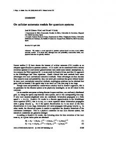
Figure.3: Illustration of a state graph in Gaspard 2) State graphs: A state graph in Gaspard as presented in Figure.3, is similar to state charts [29], used for modeling of system behavior via a state-based approach. It can be described as a graphical representation of transition functions [8]. A state graph is constructed of a set of vertices, called states. A state connects with other states through directed edges which are called transitions. Transitions can have conditions depending upon some events or Boolean expressions. A transition is triggered when its associated condition is met. A special label all, on a transition outgoing from state s, indicates any other events that do not satisfy the conditions on other outgoing transitions from s. Each state is linked to some mode value specifications that provide mode values for the state. 3) Composition of mode switch and state graph: Once mode switches and state graphs are conceptualized, a MACRO component can be used to compose them together. The
inria-00486919, version 1 - 27 May 2010
macro in Figure.4 illustrates one possible composition. The components Gaspard State Graph and Mode Switch Component are associated with state graphs and mode switches respectively. In the macro, the Gaspard state graph produces a mode value (or a set of mode values) associated with the current executing state and sends the value(s) to the mode switch component which switches the modes accordingly. Some data dependencies (or connections) between these components are not always necessary, for example, data dependency between Id and id . They are drawn with dashed lines in Figure.4. The illustrated figure is used as a basic composition, however, other variations are also possible, for instance, one Gaspard state graph can control several mode switch components. Once the macro is constructed, it is possible to create a Gaspard Mode Automata (GMA). The Gaspard state graph acts as a state-based controller and the mode switch component achieves the mode switch function. Secondly, interrepetition dependency specifications should be specified for the macro when it is placed in a repetitive context. This is because a macro component represents a single transition between states. For continuous transitions similar to mode automata, the macro must be repeated. An interrepetition dependency enables continuous sequential execution and permits creation of a mode automata. An interrepetition dependency connects the repetitions of the macro structure and conveys the current state. Hence, it sends the target state of one repetition as the source state for the next repetition of the macro. The states and transitions of the automata are represented via the Gaspard state graph. The data computations inside a mode are set in the mode switch component. The detailed formal semantics related to Gaspard mode automata can be found in [8].
allows to move from platform-independent high level models to platform-dependent models, for eventual implementation. The concept of VirtualIP represents the functionality of a given elementary component, independently from the compilation target. For an elementary component J, it associates J with all its possible IPs. The desired IP(s) is (are) then selected by the SoC designer by linking it (them) to J via an implements dependency. Finally, the CodeFile concept determines the physical path related to the source code of an IP, along with required compilation options.
Figure.5: Deployment of an elementary component Figure.5 and Figure.6 collectively represent the deployment level. The HuffmanCoding component is an elementary component of a typical Gaspard application (an H.263 codec in this case). At the deployment level, this component may have several possible implementation choices; either for the same execution platform (same abstraction level): in a given language, or for different ones. In the given example, the component can be simulated in SystemC or can be implemented as a hardware accelerator in an FPGA via VHDL. The implements dependency from the Huffman-VHDL component to the HuffmanCoding represents the targeted implementation choice/execution platform.
Figure.4: An example of the Gaspard mode automata integrated at the application level in our framework C. IP deployment in Gaspard The Gaspard IP deployment level allows one to select a specific IP for each elementary component of application or architecture, among several possible choices. The reason being: in SoC design, a functionality can be implemented in different manners. For example, an application functionality can either be optimized for a processor (written in C/C++), or implemented as a hardware accelerator using Hardware Description Languages. Hence the deployment level distinguishes between the hardware/software functionalities; and
Figure.6: Linking a CodeFile to an IP A limitation of the deployment level is that for final compilation for code generation, an elementary component can be linked to only one IP. This drawback does not effect platforms where system adaptivity in not concerned, however in the
case of dynamically reconfigurable FPGAs, this issue must be addressed. The deployment level is thus extended to integrate reconfiguration aspects which are presented later in the paper.
inria-00486919, version 1 - 27 May 2010
IV. I NTEGRATING PDR ASPECTS IN G ASPARD : A DDING C ONTROL EXTENSIONS AT IP DEPLOYMENT LEVEL For implementing PDR, an embedded reconfiguration controller has two functionalities: one responsible for communicating with the FPGA ICAP reconfigurable core; and a state machine for switching between the configurations. The first functionality is written manually due to some low level RTL details which cannot be expressed via a modeling approach; and is treated as a macro. The control model introduced at the deployment level is used to generate the second functionality automatically via model transformations. Finally the two parts can be used to implement PDR in an FPGA that can be divided into several static/reconfigurable regions. In our works, the application being modeled at the high abstraction levels in transformed into a hardware functionality, i.e., a hardware accelerator, by means of the model transformations [27]. This hardware accelerator is treated as a reconfigurable region at the RTL level. A reconfigurable region can have several implementations, with each having the same interface, and can be viewed as a mode switch component with different modes. We now explain the control model at the deployment level. We first summarize the extended version of the deployment that determines the implementations linked to the reconfigurable region, followed by the deployment control model that is responsible for generating the controller. A. Introduction of “Configurations” at the deployment level
Figure.7: Extended Gaspard deployment level Currently, an elementary component can be linked to only one IP among the different available choices (if any). Thus the result of the application/architecture (or their mapping onto each other) is a static one. This collective composition is called a Configuration. The current RTL level model transformations only permit to generate one hardware accelerator (one configuration) for final FPGA implementation.
Adopting control in deployment allows to create several configurations for final FPGA implementation. Each configuration is defined as a collection of different IPs, with each IP linked to its respective elementary component. Thus, a new stereotype ConfigurationInfo (as illustrated in Figure.7) is introduced, that is added to the implements dependency associating an IP with its corresponding elementary component. A ConfigurationNumber attribute related to this stereotype allows the designer to link, a particular IP of an elementary component, with a desired final configuration.
Figure.8: Deploying a Gaspard application having three elementary components An elementary component can also be linked to the same IP in different configurations. This point is related to the semantics of FPGA partial bitstreams which support glitchless dynamic reconfiguration. If a configuration bit holds the same value before/after reconfiguration, the resource controlled by that bit does not experience any loss in its operation. If the same IP for an elementary component is used in several configurations, that IP is not swapped during reconfiguration. Hence, it is possible to link several IPs to a corresponding elementary component; each link specifying a unique configuration. Also, for any n number of configurations, with each having m elementary components, each elementary component of a configuration must have at least one IP. This enables successful creation of a complete configuration. Finally, two enumerations, Modes and States are created. The first contains the mode values related to all possible configurations; while the second contains the states of the Gaspard state graph. With information provided in deployment and model transformations, each state (configuration) is linked to its respective IPs. Each state also has an associated Boolean flag (with a default value of 0). A value of 1 specified by the designer indicates that this state is chosen as the initial state/configuration for the Gaspard state graph. This information is then sent onto the control concept modeled in the second phase of deployment using the model transformations. Figure.7 illustrates the extended version of the deployment related to a generic elementary component while omitting the
enumerations; and Figure.8 represents an abstract overview of the deployment semantics. By modifying the RTL level model transformations, it is possible to generate different hardware accelerators (different configurations). Once the configurations are created, each is viewed as a source for a partial bitstream. Each partial bitstream signifies a unique implementation for a reconfigurable hardware accelerator, connected to an embedded controller. While this extension allows to create different configurations, the state machine part of the controller is created manually. For automatic generation of this functionality, the deployment extensions are inadequate. We then use the existing Gaspard control concepts to solve these issues.
inria-00486919, version 1 - 27 May 2010
B. Introducing control model at the deployment level The first point is related to the nature of modes in a mode switch component. For a mode switch component at the application level control model, each mode is an instance of an application component that can be either elementary, repetitive or hierarchical in nature. However, at the deployment level, a mode switch component is related to an elementary component and contains, all the related IPs as its modes. As explained in section III.B, only the input mode ports are necessary for the creation of a mode switch component. In control model at application level, the related data flow is represented via data input/output ports. However as control model at the deployment level is concerned with behavioral semantics and not structural ones, the data flow is not explicitly expressed. For all IPs linked to an elementary component, their input/output data flow values are equivalent to that of the elementary component. Model transformations are capable to link ports of each of the IPs in a mode switch component to the corresponding elementary component. This version of a mode switch component is termed as a Deployed Mode Switch Component. We apply a condition that for the construction of a deployed mode switch component, the corresponding elementary component must have more than one available IP. Another difference in the deployment control model is related to the modeling of the collaborations associated with a deployed mode switch component, for expressing its behavior. Compared to application level control model collaborations, the delegate connectors are absent between the interior parts of the deployment level collaborations due to absence of data flow [9]. Given a Gaspard state graph Q and a mode switch component P, the name of an associated collaboration corresponds to a mode value associated with a state of Q and defines the activity of P upon receiving that particular mode value. Figure.9 illustrates a deployed mode switch component and its corresponding collaborations. As a deployed mode switch component relates to only one elementary component; and an application (or architecture) can have several; this requires the creation of several deployed mode switch components being controlled by a single Gaspard state graph. The modified Gaspard state graph is termed as a Deployed Gaspard State Graph.
Figure.9: The Deployed Mode Switch Component DMSC EC A related to the elementary component EC A
Each of the deployed mode switch components receives the array of mode values and observes its own related mode values: the name of the related collaborations which are defined in the Modes enumeration. If a mode value in the array matches the mode value associated with a deployed mode switch component, it switches to the corresponding mode. However, if there is no match, it remains inactive. Once the deployed Gaspard state graph and the deployed mode switches are constructed, they are placed inside a composition called a Deployed MACRO. This composition is then placed in a repetition component to construct a Deployment Level Mode Automata. An interrepetition dependency and a defaultlink are utilized to make this mode automata equivalent to a synchronous mode automata. In the special case when an elementary component only has one available IP to be included in all the possible configurations, it has no corresponding deployed mode switch component or DMSC. In that case, the deployed state graph and the constructed DMSCs are placed in a composition called a Deployed Composition. Afterwards, the single IP belonging to the related EC is placed with this composition in the Deployed MACRO component. Subsequently, normal composition of DMA is carried out. A DMSC illustrates a choice related to the different present modes. In case of no alternatives, it is not necessary to create the DMSC. Figure.10 represents the corresponding deployment level mode automata for the example present in Figure.8. As each of the three configurations contain the single IP C1 for the elementary component EC C, this IP will always be present in the final composition of any configuration irrespective of the changes in events and the respective states. For mode automata at application level, its initial state is given by an application component that has input event ports and an output state port. Initially some events are generated and taken as input by that component in order to produce the initiate state. After that, the application component remains inactive due to the absence of the events arriving on its input ports. However, for deployment level mode automata, no structural information about application level is present except the information related to elementary components. Thus the initial state related to the deployed Gaspard state graph cannot be determined explicitly.
inria-00486919, version 1 - 27 May 2010
We thus introduce an internal component in the deployment level control model, responsible for relaying the initial state of the deployed Gaspard state graph or DGSG. This component is termed as a InitialStateComponent and contains a single output port of the enumerated States type with a shape value of {1}. This output port provides the user defined initial state of the deployed Gaspard state graph. Once a transition to another state occurs, the interrepetition dependency allows to provide the information about the previous state; and the target state is treated as the source state for the subsequent transition of the deployed Gaspard state graph.
processor is actually present in the processor sub system, of the highest hierarchical entity (i.e. top.vhd) of the PDR system. Figure.10 shows a complete overview of the deployment level control model, taking into account all the possible scenarios of elementary components and associated IPs. C. Integrating event observer at the RTL level As elaborated in the precedent section, the control events in our scenario are generally non deterministic in nature and depend upon the user input, while data computations are deterministic and arrive in a regular manner as per Gaspard semantics. Hence we need to create regularity between the control/data flows. The notion of an EventObserver is thus introduced at the RTL level in the highest hierarchical PDR system entity. This concept is not introduced at MARTE modeling level in order to distance the designer from event management details. Figure.11 shows an abstract overview of the top level entity of our PDR system. It should be reminded that the reconfigurable region, the corresponding implementations and the reconfigurable controller are generated via high level MARTE modeling.
Figure.10: An abstract overview of the Deployment Level Mode Automata It is also necessary to address the issue related to the arrival of incoming events in the deployment level mode automata shown in Figure.10. In control model at the application level, the events are either produced randomly in the application itself due to an elementary component or taken as input from the external environment (for example user defined stimuli). But for mode automata at deployment level, the incoming events need to be linked directly to this level. At the RTL level, these events are considered as the non deterministic user specified inputs taken by means of a UART interface present in the reconfigurable system. A set of options is given to the user for configuration selection. These options are treated as input events. The user can thus choose among the different modeled configurations, depending upon different QoS criteria such as reconfiguration time and consumed FPGA resources via a Design Space Exploration (DSE) strategy. To link the user specified inputs, or events, to the deployment level, the mode automata is modeled with n number of event ports, n being the number of possible configurations. Each event port has a shape value of {1,*}. The first dimension of this shape value indicates that only one event value arrives at a particular instant of time, while the second dimension indicates a temporal infinite repetition. These event ports are of the type Boolean. The event values serve to cause a transition in the deployment level mode automata. The input event ports of the deployment level mode automata are not linked to any higher abstraction level of the application, but via model transformations, at the RTL level, are in fact taken as the input ports (those related to receiving UART signals) of the embedded processor. This
Figure.11: A global overview of the our PDR system The EventObserver consumes user inputs arriving at irregular time intervals and produces events at regular time intervals for the deployed Gaspard state graph. This component has input and output event ports EventIn and EventOut respectively, as well as the Clk and Rst ports for clock and reset signals. The EventIn port is connected to the top level UART Rx input port while the EventOut port is connected to the processor’s UART Rx input port. An extract of the algorithm related to the EventObserver is presented below using an informal semantic: ———————————————————————Sensitivity List (Clk, Event) if Clk is TRUE and Event then EventOut = Event; else if Clk is TRUE and not Event then EventOut = Default Value; end if ———————————————————————The user input may arrive irregularly at any instant of time, where as an event value is need at each instant of time t. The EventObserver listens on its input port, and at each rise of clock, determines if an event is present or not. In the first case, the event is sent to the processor subsystem and in turn
the reconfiguration controller. This causes a successful state transition (or a self transition) in the state graph. In the second case, if there is no user driven input event at time t, then the EventObserver generates a default event e d, causing a self transition in the state graph. This value can be viewed as a special value among the set of values corresponding to the all expression: which catches any event not specified in related transitions and causes a self transition in the state graph. If ξ is the set of all possible events and E is the set of events related to the different configurations, The overall relation is then expressed as:
inria-00486919, version 1 - 27 May 2010
E = {e 1, e 2, e 3} , all = {ξ � E} ∪ {e d} The relations between the different events and states (configurations) in a deployed Gaspard state graph present in the controller are shown in Figure.12. A self transition does not switches the current executing configuration, while a transition to a different state causes the controller to switch to the corresponding configuration. While this notion introduces regularity in the arrival of control events, it is possible that a control event and the eventual configuration switch causes a disruption in the data flow of the application implemented as a reconfigurable hardware accelerator. It is thus critical to determine the precise moment to effectively switch a configuration. Our works could benefit from the notion of degree of granularity [7] that responds to the synchronization of the control/data flow.
Figure.12: Different representations of deployed Gaspard state graph: events and state relations V. C ONCLUSION This paper presents a novel mode automata based control model in a MDE oriented MARTE compliant SoC co-design Gaspard framework. The integration of this control model in the IP deployment level of our framework makes it possible to model aspects of partial dynamic reconfiguration. Regularity between the control/data flow is also introduced at the RTL level. As a perspective, MDE model transformations are currently being developed to enable automatic code generation for final implementation of partial dynamic reconfiguration in a targeted FPGA. This will result in a complete MDE design flow to implement dynamically reconfigurable FPGAs using a high level design flow. R EFERENCES [1] P. Lysaght and B. Blodget and J. Mason, “Invited Paper: Enhanced Architectures, Design Methodologies and CAD Tools for Dynamic Reconfiguration of Xilinx FPGAs,” in FPL’06, 2006. [2] B. Blodget and S. McMillan and P. Lysaght, “A lightweight approach for embedded reconfiguration of FPGAs,” in DATE’03, 2003.
[3] INRIA DaRT team, “GASPARD SoC Framework,” 2009, http://www. gaspard2.org/. [4] A. Gamati´e et al, “A model driven design framework for high performance embedded systems,” INRIA, Research Report RR-6614, 2008, http://hal.inria.fr/inria-00311115/en. [5] OMG, “Modeling and analysis of real-time and embedded systems (MARTE),” http://www.omgmarte.org/. [6] F. Maraninchi and Y. R´emond, “Mode-automata: About modes and states for reactive systems,” in European Symposium On Programming. Lisbon (Portugal): Springer verlag, Mar. 1998. [7] O. Labbani et al, “Introducing control in the gaspard2 data-parallel metamodel: Synchronous approach,” in Proceedings of the International Workshop MARTES: Modeling and Analysis of Real-Time and Embedded Systems, 2005. ´ Rutten and H. Yu, “A Model for the Mixed-Design of [8] A. Gamati´e and E. Data-Intensive and Control-Oriented Embedded Systems,” INRIA, http: //hal.inria.fr/inria-00293909/fr, Research Report RR-6589, July 2008. [9] H. Yu, “A MARTE-Based Reactive Model for Data-Parallel Intensive Processing: Transformation toward the Synchronous Model,” Ph.D. dissertation, USTL/LIFL, France, 2008. [Online]. Available: http: //sites.google.com/site/huafengyu/pub-files/thesis.pdf [10] Y. Atat and N. Zergainoh, “Simulink-based MPSoC Design: New Approach to Bridge the Gap between Algorithm and Architecture Design,” in ISVLSI’07, 2007, pp. 9–14. [11] G. Gailliard et al, “Transaction level modelling of SCA compliant software defined radio waveforms and platforms PIM/PSM,” in DATE’07, 2007. [12] S. Mohanty et al, “Rapid design space exploration of heterogeneous embedded systems using symbolic search and multi-granular simulation,” in LCTES/Scopes, 2002. [13] A. Koudri et al, “Using MARTE in the MOPCOM SoC/SoPC CoMethodology,” in MARTE Workshop at DATE’08, 2008. [14] F. Berthelot and F. Nouvel and D. Houzet, “A Flexible system level design methodology targeting run-time reconfigurable FPGAs,” EURASIP Journal of Embedded Systems, vol. 8, no. 3, pp. 1–18, 2008. [15] M. Boden et al, “GePARD - a High-Level Generation Flow for Partially Reconfigurable Designs,” in ISVLSI 2008, 2008. [16] R. Damasevicius and V. Stuikys, “Application of UML for hardware design based on design process model,” in ASP-DAC’04, 2004. [17] W. McUmber and B. Cheng, “UML-based analysis of embedded systems using a mapping to VHDL,” in IEEE International Symposium on High Assurance Software Engineering, HASE’99, 1999, pp. 56–63. [18] P. Sedcole et al, “Modular Partial Reconfiguration in Virtex FPGAs,” in FPL’05, 2005, pp. 211–216. [19] J. Becker and M. Huebner and M. Ullmann, “Real-Time Dynamically Run-Time Reconfigurations for Power/Cost-optimized Virtex FPGA Realizations,” in VLSI’03, 2003. [20] M. Huebner et al, “New 2-Dimensional Partial Dynamic Reconfiguration Techniques for Real-Time Adaptive Microelectronic Circuits,” in ISVLSI’06, 2006. [21] C. Schuck et al, “A framework for dynamic 2D placement on FPGAs,” in IPDPS 2008, 2008. [22] Xilinx, “Early Access Partial Reconfigurable Flow,” 2006, http://www. xilinx.com/support/prealounge/protected/index.htm. [23] S. Bayar and A. Yurdakul, “Dynamic Partial Self-Reconfiguration on Spartan-III FPGAs via a Parallel Configuration Access Port (PCAP),” in HiPEAC’08 Workshop on Reconfigurable Computing, 2008. [24] C. Claus et al, “A new framework to accelerate Virtex-II Pro dynamic partial self-reconfiguration,” IPDPS 2007, pp. 1–7, 2007. [25] A. Cuoccio et al, “A Generation Flow for Self-Reconfiguration Controllers Customization,” Forth IEEE International Symposium on Electronic Design, Test and Applications, DELTA 2008, pp. 279–284, 2008. [26] R. Koch et al, “An adaptive system-on-chip for network applications,” in IPDPS 2006, 2006. [27] I.-R. Quadri, S. Meftali, and J.-L. Dekeyser, “A model driven design flow for fpgas supporting partial reconfiguration,” International Journal of Reconfigurable Computing, 2009, Hindawi Publishing Corporation, Tentative publication date : June 2009. [28] P. Boulet, “Array-OL revisited, multidimensional intensive signal processing specification,” INRIA, http://hal.inria.fr/inria-00128840/en/, Research Report RR-6113, February 2007. [29] D. Harel, “Statecharts: A Visual Formalism for Complex Systems,” Science of Computer Programming, vol. 8, no. 3, pp. 231–274, June 1987.