software codesign, partitioning and scheduling. Much of ... UltraSONIC using the new hardware-software system model. ..... Field-. Programmable Logic and Applications (FPL), 2002. [6] Haynes S. D., Stone J., Cheung P. Y. K., Luk W., Video.
MULTITASKING IN HARDWARE-SOFTWARE CODESIGN FOR RECONFIGURABLE COMPUTER T. Wiangtong1, P.Y.K. Cheung2, W. Luk3 1
Electronic Department, Mahanakorn University of Technology, Bangkok, Thailand Department of Electrical & Electronic Engineering, Imperial College, London, UK 3 Department of Computing, Imperial College, London, UK
2
ABSTRACT This paper presents a new approach for modeling hardware and software tasks in codesign system. The model has the advantage that the hardware tasks are structured in a way that is compatible with the software tasks. As a result, both hardware and software tasks can be managed in a uniform manner using a single task manager. A hardware/software partitioning and schedule algorithm is developed to automatically map the tasks to the codesign resources to minimize the processing time (makespan). The practicality of our approach is demonstrated with an implementation of dummy tasks for an existing reconfigurable computer, the UltraSONIC. The results show that our approach is promising for a real application.
The novel contributions of this paper are: 1) a new way of structuring and modeling hardware tasks in a codesign system; 2) a partitioning and scheduling algorithm that employs this method; 3) applying the algorithm to a realistic reconfigurable computer system; 4) evaluation and verification of our model using the reconfigurable computer. The rest of this paper is organized as follows. Section 2 presents how the hardware and software tasks are modeled in the codesign system. Section 3 describes the environment in which the codesign system works. In Section 4, the UltraSONIC system used as the realistic target for our partitioning and scheduling software is briefly described. Section 5 gives the experimental results of the partitioning and scheduling algorithm applied to the UltraSONIC system and Section 6 concludes this paper.
1. INTRODUCTION Most reconfigurable systems contain both hardware and software resources that must work cooperatively with each other. This has fueled the interest in research into issues relating to hardwaresoftware codesign, partitioning and scheduling. Much of this research assumes a general system model that ignores realistic issues such as bus and memory contentions [1][2]. Others ignore the cost of communications completely [3]. In addition, traditional formulation of the partitioning and scheduling problem for a codesign system also employs a hardware model that is totally different from that used in software. This is understandable because most codesign systems have one or more microprocessors responsible for software tasks that are controlled by a multitasking operating system, while the hardware tasks are implemented separately from the software, with different optimization constraints (such as the degree of parallelism, speed and hardware resources). The end results are algorithms and systems that do not take a uniform view of the hardware and the software resources. This paper reports a new method of constructing hardware tasks in a codesign system that makes them more compatible with software tasks without sacrificing the benefit of concurrency found in conventional hardware implementations. At the same time, it exploits the advantages of modularity, cohesion and structured approach offer by software tasks. We further present a partitioning and scheduling algorithm reported previously [4], but applied to a reconfigurable computer system known as UltraSONIC using the new hardware-software system model. This demonstrates the potential of our model and our partitioning/scheduling algorithm when applied to a realistic system.
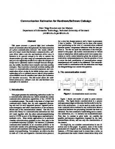
2. SYSTEM MODEL Figure 1 shows the hardware/software system model adopted in this work. We assume the use of a single processor (software) resource SW capable of multitasking, and a number of concurrent hardware processing elements PE0 to PEn, which are assumed to be implemented on FPGAs. We employ a loosely coupled model with each processing element (PE) having its own single local memory. All system constraints such as shared resource conflicts, reconfiguration time (of the FPGAs) and communication time are taken into account. Global Communication Channel task 0 task 5
Local Communication Channel
Task manager program
task 1
task 2
task 3
task 12
task 4
PE0
on fig
task 8 task 9
Mem
Re c
task 7
Mem
SW
task 8 task 10
Mem
task 10 task controller & memory interface
PE1
Mem
PEn
Figure 1. Codesign system modeling The assumptions used in our model are: 1) tasks implemented in each hardware PE are coarse grain tasks representing blocks, loops, or functions; 2) local memory is single port, and only one task can access the local memory at any given time; 3) tasks for a PE can be dynamically swapped in through dynamic reconfiguration; 4) each task is small enough to fit into a single PE; 5) multiple tasks residing in a given PE execute sequentially;
6) tasks residing across different PEs can execute concurrently; 7) a global communication channel is available for the processor and the PEs to communicate with each other; 8) local communication channels are available for neighboring PEs to communicate with each other in a pipeline ring; 9) a task manager program is used in the software processor to manage all tasks–software and hardware. This system model effectively makes the hardware tasks look very much like software tasks. In this way, the management of task scheduling, task swapping and task allocation can be done in a uniform manner, no matter whether the task in question is implemented in hardware or in software. Concurrency is not affected as long as we map concurrent tasks onto separate PEs. Although conceptually different PEs are separate from each other, multiple PEs may be implemented in a single FPGA device.
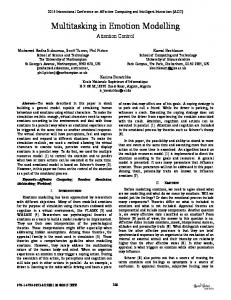
3. CODESIGN ENVIRONMENT Figure 2 depicts the codesign environment of our system. The system to be implemented is assumed to be described in some suitable high level language, which is then mapped to a directed acyclic graph (DAG). Tasks are represented by nodes and communications by edges in the DAG. The nodes are then partitioned into hardware or software tasks, and are scheduled to execute in order to obtain the minimum makespan (total processing time). The partitioning and scheduling software used is adapted from tabu search and list scheduling algorithms reported earlier by the authors [4]. After getting results of partitioning and scheduling that inform where tasks are implemented and when tasks are executed, a Task Manager (TM) program can be produced. Its functions are described below.
DAG
Partitioning and scheduling
Mapping and scheduling results
High level language
SW task codes
Task manager program
HW Config files
SW
HW Communication channels
Task manager program
PE0
PE1
Mem Mem
Mem
Figure 2. The codesign environment Central to our approach is the use of the Task Manager (TM) program running in the processor (software) resource to manage both hardware and software tasks. This program controls the sequencing of all the tasks, the transfer of data and the synchronization between them, and the dynamic reconfiguration of the FPGA in the PEs if required. Figure 3 shows the conceptual block diagram of the TM and its operation. The TM communicates with a Local Task Controller on each PE in order to assert control. A message board is used in each PE to receive commands from TM or to flag finishing status to TM.
Message board
Message board Global variable for SW tasks
task 0 task 2
Task manager program
Registers Start (TaskID)
task 1
Stop (TaskID)
Check operation massages on each PE and decide when to + run HW tasks + run SW tasks in background (multithread) + reconfig HW tasks + transfer data between PIPE
Data Transfer
task 3
Finish Transfer
PE0
Task Controller
Message board
Registers Data Transfer
task 4
Finish Transfer
task 5
Start (TaskID) Stop (TaskID)
SW
PE1
Task Controller
Figure 3. The task manager This system employs a message-based protocol when running a process. For example, messages indicating execution completion from tasks are posted to registers inside the PEs to inform the task manager program. When this program−written to poll these registers−finds the message, it can then decide what to do next. By using this method, tasks on each PE is run independently by the task manager program created from partitioning and scheduling results. Hence the program operates asynchronously at system level. In lower level (task-level), however, functions are executed synchronously and sequentially inside each PE, thus making execution time predictable.
4. VERIFICATION IN RECONFIGURABLE COMPUTER In order to verify the practicality of our model and the effectiveness of our partitioning/scheduling algorithm, we implement the system described in the previous sections on a high performance reconfigurable computer known as UltraSONIC. UltraSONIC [5][6] is a reconfigurable computing system designed to cope with the computational power and the high data throughput demanded by real-time video applications. The system consists of Plug-In Processing Elements (PIPEs) interconnected by local and global buses. The architecture exploits the spatial and the temporal parallelism in video processing algorithms. It also facilitates design reuse and supports the software plug-in methodology. The basic PIPE consists of three parts (see figure 4): PIPE engine, PIPE router and PIPE memory. The PIPE engine handles computation while the PIPE router is responsible for image data movement and formatting. The PIPE memory provides local buffering of video data therefore reducing bus traffic. UltraSONIC uses a Virtex XCV1000E device implementing both the PIPE engine and the PIPE router. The PIPE memory is implemented with synchronous SRAM, which allows fast and easy memory access. The program on the host system (PC) controls operations in the platform−such as setting registers, configuring selected PIPEs, loading or retrieving images from PM−through 64-bit PCI bus running at 66MHz by using a set of
well-defined SONIC Application Programming Interface (API) functions. PIPE Bus - 64bit Address/Data and 2 bit control LBC (Local BusController) XCV300
PIPE 1
PIPE 2
PIPE 16
PIPE 3 Global PipeFlow Bus 32bit + 2bit Ctrl
PCI PipeFlow Chain 32bit + 2bit Ctrl PCI Bus 64bit 66MHz
5. RESULTS PEregister StartXReg
Task A
FinishXReg
PEtask
InterPIPETrfReg
Task B
InterPIPETrfCmd
PEtask
TaskDataInReg0 TaskDataInReg1
DataOUT
Task C DataIN
Figure 5 illustrates a task model. A hardware task resides in a standard frame consisting of I/O shift registers, I/O buffers, and control block (called hardware overhead). Because of single local memory, to represent several incoming/outgoing edges of a task in DAG, we have to use shift register to read/write data from memory. The standard frame can be parameterized to suit with input/output requirements in each task.
Vertex Device XCV1000E
PIPE Engine
TaskDataInReg2
PEtask TaskReq
TaskDataInReg3 TaskAck
TaskDataOutReg0 TaskDataOutReg1
Controller
TaskDataOutReg2
PF IN
TaskDataOutReg3 PF OUT
memory interface, currently we only employ a single port access in our model.
PEcontroller
PortA
PIPEBus
TaskDataCtrlReg0
Memory Interface
PortB
TaskDataCtrlReg1
Address
PFmemIN
PFmemOUT
Data IN/OUT
Bus Control & Routing
Page1 Page2 Page3
MemControl Local Memory 2x4MB
PIPE Memory
PIPE Router
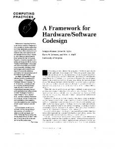
In order to verify that the implemented system works, we apply the partitioning and scheduling program to a randomly generated DAG which contains 15 tasks. This is shown in figure 6 alongside the execution time of each task in software and hardware respectively. Numbers on edges are the amount of data (KB) transferred between tasks. From these, the graph is partitioned and scheduled using the Tabu search and list scheduling algorithm adapted from our previous work [4]. The objective is to minimize the processing time (makespan). The result of the partitioning algorithm is also shown in figure 6. Tasks {0, 1, 3, 6, 8, 9, 12} are implemented in PIPE1 and Tasks {2, 4, 7, 10, 11, 14} in PIPE0. Tasks 5 and 13 are implemented in the host processor. The results of the scheduling algorithm and communication channels between tasks are shown in figure 7. PFG bus is used to transfer data between tasks located on different PIPEs (InterPIPETrf), while PB is used for communication between software and hardware tasks including data transfer and message transfer. 15
Pagen
PF Left (PFC)
PFG
PIPE1
PF Right (PFC)
46
15
Figure 4. Codesign model implement on UltraSONIC PIPE
1 86
O/P shift reg
O/P buffer
I/P buffer
I/P shift reg
3 99
HW overhead 12
6
5 27
7
30
10
3
10
38
1
6
Comparing to the model depicted in figure 1, UltraSONIC system employs PIPE Bus (PB) as a global communication channel interfacing between software and hardware. Global PipeFlow Bus (PFG) represents local communication channel between PIPEs. This figure also shows how our codesign model is implemented in the UltraSONIC PIPE. The Local Task Controller implements the message passing protocol to control the operation of all the hardware tasks resident in this PIPE. The message board is implemented in PEregister. Various hardware tasks are implemented in the PIPE engine hardware resources. Although the UltraSONIC PIPE is designed with a dual-port
39
61
9
8
Figure 5. Task model
84
6 84
control
78
21 4
99
PIPE0 2
24
Circuit
Task No. 0
0
91 13
1
68
SW Exec Time (µ µs) 4007
HW Exec Time (µ µs) 3254
1
8852
3339
2
6101
4583
3
8479
2502
4
8262
3054
5
5089
1365
6
4883
6482
7
6674
3179
8
4053
9
7427
3406
10
7997
3652
11
6112
1228
12
8699
4210
13
5811
4503
14
9735
4702
2011
11
28 30
4
Task implemented in PIPE0
0
Task implemented in PIPE1
5
Task implemented in SW
14
28
Figure 6. Implemented DAG after partitioning The DAG is artificially generated and is used to verify the operation of the entire system by emulating each task with a “dummy” hardware or software module. Each task module mimics the exact input and output data transfer (emulating the communication between tasks) and takes the same amount of time to execute as the actual system (emulating the processing time of each task).
Figure 8 shows the overall timing obtained from hardware (PIPE0, PIPE1) when the DAG in figure 6 is implemented on the UltraSONIC system. Although the Task Manager can conduct operations−running tasks and transferring data−in the right execution order as shown in the scheduling diagram, the total processing time is found to be around 42ms, which is more than the 31.2ms predicted by the partitioning and scheduling algorithm. The discrepancy can be explained by the message transferring time incurred by the Task Manager which is not included in our model. From some additional experiments, we found that it takes 60µs/message. Therefore this overhead can be estimated by using the number of sending/receiving messages happen in Task Manager. In the case of this implementation, it is about 9.7ms which, when added to the predicted makespan, yields a time fairly close to the measured result. PE0
SW
0
0
G PF
PFG
1
2
1
G PF
(4)
5
4
G PF
3
PB
PB
3
78K
PB
86K
7
6
PFG
5
8
11
PB
61K PFG
12
10
PB
PB
30K PB
9
11
PF G
Processing Time (Makespan)
4
27K
Operations on PIPE0
13
14
Time (ms) Start Stop
Run Task2
0.000
Period
Operations on PIPE1
Communication channels between tasks 9 10
8 1K+38K 91K PFG
14
0.000
Period
4.351
Run Task0
0.725
InterPIPETrf (46K)
2.929
Run Task1
0.473
Run Task3
3.253 3.789 4.146 4.912 8.252 8.701 11.204
1.229
InterPIPETrf (86K)
12.912 13.579
0.667
20.295 20.827
0.532
3.253
InterPIPETrf (61K) Run Task11
17.997 19.226
Run Task7
19.776 22.956
3.180
InterPIPETrf (61K)
Run Task10
23.376 26.997
3.621
Run Task6
21.364 27.848
6.484
InterPIPETrf (91K)
32.162 32.927
0.765
Run Task9
28.352 31.759
3.407
Run Task14
33.391
4.192
Run Task8
32.304
InterPIPETrf (91K)
36.784 37.490 38.249 42.459
37.583
Run Task12
34.301
0.357 3.340 2.503
1.997 0.706 4.210
Figure 8. Results showing start and stop time of each HW task
7
13
Start Stop
6
PB
Time (ms)
4.351 8.291 9.016 9.433 12.362 15.790 16.263
Run Task4
0
46K
PB
The future work will include: 1) this TM overhead in our model; 2) extending our approach to deal with a realistic problem, such as implementing a complex video processing algorithm on this system.
InterPIPETrf (86K)
PE1
2
experiment we conducted showed that our overall system works satisfactorily. However, in order to achieve better predicted makespan by the scheduling algorithm, the Task Manager communication overhead must be taken into account by our model.
12
31.196 ms
Figure 7. Scheduling diagram and communication channels
6. SUMMARY This paper presents a way of modeling and implementing hardware tasks in a codesign environment such that they can be task managed in the same way as software. The model makes it easier for partitioning algorithms to select between software or hardware implementation. The proposed use of a unified Task Manager running in the processor also allows a single runtime environment to be used for the codesign system. The proposed system is implemented on a realistic reconfigurable computer, the UltraSONIC. An existing partitioning and scheduling algorithm adapted to suit our new environment proves to be effective. The
7. REFERENCES [1] Kai M., Shimada M., “Task scheduling algorithms based on heuristic search taking account of communication overhead”, Communications, Computers and Signal Processing, 1999 Page(s): 145 –150 [2] Topcuoglu H., Hariri S., Min-You Wu, “Performanceeffective and low-complexity task scheduling for heterogeneous computing”, IEEE Transactions on Parallel [3] Freund L., Israel M., Rousseau F., Berge, M., Auguin, M., Belleudy C., Gogniat, G., “A codesign experiment in acoustic echo cancellation: GMDF”, System Synthesis, 1996 [4] Wiangtong T., Cheung P. Y. K., Luk W., "Comparing Three Heuristic Search Methods for Functional Partitioning in HW-SW Codesign", International Journal on Design Automation for Embedded Systems, Kluwer Academic Publishers, 2002, Page(s) 425-449. [5] Haynes S. D., and others, UltraSONIC: A Reconfigurable Architecture for Video Image Processing. FieldProgrammable Logic and Applications (FPL), 2002 [6] Haynes S. D., Stone J., Cheung P. Y. K., Luk W., Video Image Processing with the Sonic Architecture. IEEE Computer, April 2000, Page(s) 50-57.