into current wireless local area network (WLAN) standards, dynamic OFDMA raises .... OFDMA in IEEE 802.11a as well as the advantages and disadvantages of ...
In Proc. 3rd Intl. Conf. on Testbeds and Research Infrastructures for the Development of Networks and Communities (TridentCom), May 2007
Integrating multiuser dynamic OFDMA into IEEE 802.11a and prototyping it on a real-time software-defined radio testbed Hermann S. Lichte∗ , Stefan Valentin∗ , Falk Eitzen∗ , Matthias Stege† , Carsten Unger† , and Holger Karl∗ ∗ University
of Paderborn, Warburger Str. 100, 33098 Paderborn, Germany {hermann.lichte|stefanv|folk|holger.karl}@upb.de, Phone: +49 5251.60-5374, Fax: +49 5251.60-5377 † Signalion
GmbH, Sudhausweg 5, 01099 Dresden, Germany {matthias.stege|carsten.unger}@signalion.com, Phone: +49 351.206931-0, Fax: +49 351.206931-11
Abstract—Multiuser dynamic orthogonal frequency division multiple access (OFDMA) can achieve high downlink capacities in future wireless networks by optimizing the subcarrier allocation for each user. When it comes to the integration into current wireless local area network (WLAN) standards, dynamic OFDMA raises several implementation issues which are neglected in theoretical papers. Putting this emerging approach into practice requires to treat these issues accordingly and to demonstrate the feasibility of the system design. In this paper, we propose a dynamic OFDMA integration for the physical layer of the widespread IEEE 802.11a standard. To test our implementation and demonstrate its practical relevance we use a pragmatic approach: We prototype multiuser dynamic OFDMA on a real-time software-defined radio testbed for WLANs. We discuss details of our implementation and provide measurements showing that it does not introduce significant overhead into the IEEE 802.11a system at high subcarrier allocation quality. We particularly focus on the problems of our integration as well as the concepts and limitations of the used testbed.
Recently, many promising dynamic OFDMA schemes for maximizing the capacity of the OFDM downlink were proposed. Typical examples are schemes that maximize the transmission rate per user by subcarrier allocation only [5], [6], that combine it with power allocation [1], [2], or that minimize the delay for real-time traffic support [7]. These and further extensive theoretical studies show that performance metrics such as throughput and delay can be optimized using the dynamic OFDMA approach. Unfortunately, most of these studies make one or several of the following simplifications: •
I. I NTRODUCTION Multiuser dynamic orthogonal frequency division multiple access (OFDMA) is an emerging approach for resource allocation in wireless local area networks (WLANs) as well as mesh and cellular scenarios [1], [2]. This approach combines orthogonal frequency division multiplexing (OFDM) multicarrier modulation, rate adaptation, and subcarrier scheduling. OFDM is a well-established technique to combat inter-symbol interference (ISI) in wideband systems [3]. Rate adaptation estimates the achievable rate per subcarrier based on channel state information (CSI), e.g., according to the Receiver-Based Auto-Rate (RBAR) [4] protocol. The subcarrier scheduler then maximizes performance if it can find and allocate the best disjoint sets of subcarriers for all users. This is due to the fact that in frequency-selective multiuser environments equal subcarrier states are unlikely for all users, i.e., multiuser diversity. With time-selective fading channels, typical in mobile scenarios, the subcarrier states may change over time. Hence, even the optimal subcarrier allocation per user may change and has to be regularly updated. These dynamics challenge static OFDMA schemes where each user receives a predetermined frequency band to use with OFDM.
•
•
No control information exchange required: For dynamic OFDMA, data has to be exchanged between stations to ensure that CSI is available at the subcarrier scheduler and that the allocated subcarrier set is known at the user terminal’s physical layer. This control information has to be handled efficiently to ensure that the multiuser diversity gain introduced by dynamic OFDMA is not wasted by its overhead. The effect of this overhead is extensively studied in [8], which also introduces a simple but efficient signaling scheme. Perfect CSI at the scheduler: Many studies assume that the subcarrier scheduler can adjust its selection to the current subcarrier channel state. This assumes that the radio channel changes less frequently than its state is updated at the scheduler. Such long coherence times are not realistic in mobile scenarios [9], e.g., car or train communication. Assuming current CSI at the scheduler in these scenarios is not realistic without introducing significant control overhead for frequent CSI updates. Recent studies have shown that assuming imperfect CSI at the scheduler severely degrades dynamic OFDMA performance [8]. No additional computational complexity: Despite the control data overhead, dynamic OFDMA functions introduce additional runtime into the system. User data has to be mapped between arbitrary sets and numbers of subcarriers. This requires flexible frequency division multiplexing (FDM) functions which must consider the subcarrier
In Proc. 3rd Intl. Conf. on Testbeds and Research Infrastructures for the Development of Networks and Communities (TridentCom), May 2007
allocation during demultiplexing and multiplexing. This adds more complex demultiplexers to a user’s station than in a standard frequency division multiple access (FDMA) system, even if dynamic OFDMA is only employed at the downlink. • No integration into current standards: Standardized wireless devices enable mobile communication at low cost and are widely adopted. Successful wireless standards such as IEEE 802.11 are continuously improved by integrating new techniques [3], [10]. Although integration may lead to lower performance than a completely new design, it decreases standardization time and provides the basis for backward compatibility. While these simplifying assumptions may be reasonable for studying new approaches theoretically, designing practically relevant dynamic OFDMA systems requires to address these issues. In this paper, we use a pragmatic approach to tackle the above implementation and integration issues: We prototype multiuser dynamic OFDMA on a real-time WLAN testbed. Unlike theoretical studies this approach cannot neglect many implementation-specific problems such as handling control information and computational complexity. Furthermore, system performance can be studied under realistic CSI conditions. We extend the IEEE 802.11a physical layer and demonstrate the feasibility of this extension by runtime performance measurements. We also discuss the challenges of a multiuser dynamic OFDMA integration. Similar to theoretical studies [1], [2], [5]–[7] we focus on the OFDM downlink. To limit computational complexity we employ a suboptimal subcarrier scheduling algorithm which does not compute the optimal solution and neglects power adaptation. We study the computational cost of this solution and compare the allocation’s quality to improved subcarrier allocation algorithms. The realtime implementation of dynamic OFDMA requires extensive changes at the IEEE 802.11a physical layer. These changes have to be supported by the testbed, which is the case with the S ORBAS prototyping platform [11]. Following the softwaredefined radio (SDR) approach [12], S ORBAS includes a fully programmable IEEE 802.11a physical layer and medium access control (MAC) sublayer. Due to the computational complexity of physical layer and MAC functions the S ORBAS platform includes non-trivial hardware and software co-design as well as powerful general-purpose hardware, similar to [13], [14]. While this platform provides the required flexibility, it increases the complexity of the implementation due to hardware constraints and technical limitations. Since S ORBAS is a typical working environment for wireless communication systems, the insights gained from our dynamic OFDMA integration can be transferred to similar environments. Here, we particularly focus on the additional overhead of dynamic OFDMA in IEEE 802.11a as well as the advantages and disadvantages of the S ORBAS testbed. The paper is structured as follows. Section II provides a detailed description of S ORBAS and Section III shows performance results for this platform. In Section IV we provide
details and performance studies of our IEEE 802.11a dynamic OFDMA extensions. Section V discusses problems and limitations of our implementation on the S ORBAS prototyping platform. Finally, we conclude the paper in Section VI. II. T HE WIRELESS PROTOTYPING PLATFORM S ORBAS 101 S ORBAS is a commercially available SDR supplied with an implementation of the IEEE 802.11a physical layer and MAC sublayer [11]. The functionalities defined in the standard are implemented on field programmable gate arrays (FPGAs) and digital signal processors (DSPs). Engineers can modify any feature of the system by modifying software. As a result, flexible tests of new wireless system approaches, physical layer enhancements, or MAC modifications can be accomplished. S ORBAS operates in the 2.4 GHz industrial, scientific, and medical (ISM) band as well as in the 5 GHz range. The stations are equipped with a 10/100 Mbps Ethernet interface, for which a user datagram protocol (UDP) interface is provided to exchange control and payload data between a S ORBAS unit and a host PC. Higher layers of the protocol stack such as logical link control (LLC), the Internet protocol (IP), and the transmission control protocol (TCP) are also located on the host. A. Hardware Overview S ORBAS is based on modular prototyping hardware that comprises the following components: SRFC: RF-frontend with D/A and A/D converters, received signal strength indicator (RSSI) generation, and clear channel assessment (CCA), SDCxC: Xilinx FPGA and Analog Devices TigerSHARC DSP for digital signal processing of the physical layer and MAC, SMAC: Analog Devices Blackfin DSP for MAC processing and interfacing, and SHPM5: RF power amplifier. Fig. 1(a) shows the structure of the hardware modules and their interconnections. S ORBAS contains two SDCxC boards due to the tremendous processing power required at the physical layer. The interfaces between the two TigerSHARC DSPs and between the TigerSHARC DSPs and the Xilinx FPGAs are based on the Analog Devices link port technology. Link ports provide full-duplex point-to-point communication channels. In S ORBAS, these channels convey control information and frame data separately in both directions. The connection of the Blackfin DSP to the Xilinx FPGA on SDCxC 2 is based on an asynchronous memory interface. A proprietary interface scheme is used to connect the SRFC board components to the Xilinx FPGA on SDCxC 1. The primary external interface of S ORBAS is a 10/100 Mbps Ethernet port. Additional interfaces provided by the SMAC card are USB 2.0 and RS-232/UART, which can be used for debugging. Programming of the FPGAs and DSPs is supported by dedicated JTAG interfaces accessible from the station’s housing backside as depicted in Fig. 1(b). Further details about the S ORBAS hardware can be found in [11].
In Proc. 3rd Intl. Conf. on Testbeds and Research Infrastructures for the Development of Networks and Communities (TridentCom), May 2007 SRFC
SDCxC 1 Power Supply
(5 GHz)
RF Frontend 2.4/5 GHz BW: 20MHz
MxFE (D/A, A/D) AD9861
(2 GHz)
Power Supply
Clock Manager
SDCxC 2 32 MByte SDRAM
USB 2.0
SMAC 32 MByte SDRAM
USB 2.0
Power Supply
Power Supply 512 kByte Boot Flash
Ctl 1
JTAG
32 MByte SDRAM
RSSI 1 I1
DATA
Q1
ADR XILINX Virtex II XC2V 2000
Clk
ADSP-TS201/2S 500 MHz
ADSP-TS201/2S 500 MHz
XILINX Virtex II XC2V 2000
Ctl
ADSP-BF533 600 MHz
I2
RF Frontend 2.4/5 GHz BW: 20MHz
Reset Clock
Q2
(5 GHz)
MxFE (D/A, A/D) AD9861
RSSI 2 Ctl 2
512 kByte Boot Flash
512 kByte Boot Flash 100 MBit Ethernet
(2 GHz)
JTAG for FPGA
512 kByte Boot Flash
JTAG for DSP
512 kByte Boot Flash
JTAG for DSP
USB 2.0
RS 232
JTAG for FPGA
Host PC
(a) The IEEE 802.11a physical layer is implemented on two SDCxC boards, whereas the MAC sublayer resides on the SMAC board [11]. Physical Layer
MAC Sublayer
UDP Interface
Physical Layer TX Control/Configuration
Analog
Digital Frontend TX
OFDM Demodulator
Encoding Interleaving
Timer
Frontend Digital Frontend RX
OFDM Demodulator
Deinterleaving
lwIP Stack
CRC
Viterbi Decoding
MAC Kernel Ethernet driver
Encryption
Physical Layer RX Control/Configuration SRFC IFX Transmission
(b) Front and rear view of S ORBAS. Fig. 1.
SDCxC 1 FPGA Frontend
TigerSHARC Slave
SDCxC 2 TigerSHARC Master
FPGA Hardware Accelerator
SMAC Blackfin
(c) Mapping of physical and MAC functions to S ORBAS hardware components.
Overview of the S ORBAS modular prototyping platform for WLAN systems.
B. Software Overview Fig. 1(c) shows how particular functions of physical layer and MAC sublayer are mapped to the hardware components shown in Fig. 1(a). The physical layer software comprises a master part on SDCxC 2 and a slave part on SDCxC 1. The master performs scrambling/descrambling, convolutional encoding/Viterbi decoding, and interleaving/deinterleaving. With the exception of Viterbi decoding, all components are written in C and execute on the DSP. SDCxC 1 contains the slave part which focuses on mapping/demapping and the fast Fourier transform (FFT) and its inverse. Since the FFT is performancecritical, it is written entirely in assembler. The separated design of the physical layer exploits parallelization through pipelining. When the master DSP receives a MAC frame as a bitstream from the upper layer, it performs scrambling, convolutional encoding, interleaving, and puncturing on the bitstream and divides it into chunks. These chunks contain as many bits as are to be mapped to OFDM symbols. Then, dynamic memory access (DMA) is used to transfer one or more chunks via link port to the slave DSP for mapping and inverse fast Fourier transform (IFFT). As a consequence, the master DSP can continue with processing the next sequence of bits while the slave simultaneously performs the mapping
and computes the IFFT. The MAC protocol is implemented primarily on the Blackfin DSP. Some basic functional units (cyclic redundancy check (CRC), timers, RC4 encryption and decryption) were moved to the attached FPGA. The MAC protocol is implemented as an automaton in the specification and description language (SDL). However, significant parts of the SDL code were replaced by hand-optimized C code to meet real-time requirements. The MAC comprises the complete IEEE 802.11 standard except its extensions like IEEE 802.11e or IEEE 802.11h. The interface of the S ORBAS MAC to higher protocol layers and the MAC sublayer management interface is accessible via the UDP interface. Service primitives are defined which can be sent to and received from a S ORBAS station within UDP datagrams. These primitives are implemented in conformance to the IEEE 802.11 standard. For testing and reference purposes, a terminal application is provided with S ORBAS that can be used to generate and receive service primitives. Fig. 2 summarizes the modeling and programming languages that are used to prototype a wireless communication system on S ORBAS. Since the protocol automaton is modeled in SDL, it must be translated into C code before it can be compiled for the Blackfin DSP.
In Proc. 3rd Intl. Conf. on Testbeds and Research Infrastructures for the Development of Networks and Communities (TridentCom), May 2007
Telelogic SDL Suite
Asm.
9
VHDL Xilinx ISE MAC Sublayer
PHY Layer
PC Interface
Fig. 2. Programming languages and tools that are involved in the S ORBAS IEEE 802.11a implementation.
8 7 Effective data rate [Mbits/s]
C Analog Devices VisualDSP++
C−Compiler
SDL
6
BPSK R=1/2 BPSK R=3/4 QPSK R=1/2 QPSK R=3/4 16−QAM R=1/2 16−QAM R=3/4
5 4 3 2 1
III. T ESTBED PERFORMANCE STUDY
IV. P ROTOTYPING IEEE 802.11 A DYNAMIC OFDMA Multiuser dynamic OFDMA systems consist of four basic components: Rate adaptation, subcarrier scheduler, dynamic OFDMA-capable FDM functions, and a signaling protocol to exchange control information. Since we use a simple signaling scheme which exchanges data using the IEEE 802.11 physical layer convergence procedure (PLCP) header [8], we only focus
1
2
3
4 5 6 7 Input data rate [Mbits/s]
8
9
10
11
10
11
(a) Effective data rate of a wired connection. 9 8 7 Effective data rate [Mbits/s]
To investigate the behavior of the prototyped wireless communication system for different application scenarios (i.e., behavior on the application layer), a device driver is required that makes S ORBAS appear like an ordinary WLAN modem. We implemented a Linux kernel module that provides a virtual network device for this purpose. The network device can be configured and used through the Linux proc-interface, a pseudo file system providing direct access to kernel data structures. For performance analysis on the application layer, we measured UDP data rate and packet loss rate using our driver and the network utility iperf [15]. The measurement was conducted for two scenarios: In the first scenario, two S ORBAS units were connected with each other by wire with a 20 dB attenuator. This setup avoids transmission errors owing to the wireless channel. For the second scenario, a wireless connection via antennas was used. Each S ORBAS unit executed the unmodified IEEE 802.11a implementation. At the time of measurement, S ORBAS only supported physical data rates up to 36 Mbits/s. The implementation of the 64-QAM modulation, which yields physical data rates of 48 and 54 Mbits/s, was subject to phase inaccuracies in the analog frontend. This will be fixed by the manufacturer in future releases. Fig. 3 shows the results for the data rate measurements. For each measurement, the S ORBAS unit was configured to use a fixed modulation type. The input data rate started at 0 kbits/s and increased in steps of 200 kbits/s. Transmit power was fixed at 5 dBm. Fig. 3(a) shows the results of a wired connection and Fig. 3(b) those of the wireless one. The results of both measurements are quite similar. Only for the highest supported modulation type, the wireless measurements indicate a lower data rate. As shown, for each supported transmission rate a threshold exists where the maximum throughput is reached and the connection is saturated. Naturally, this leads to increased packet loss rates and decreased effective throughput.
0 0
6
BPSK R=1/2 BPSK R=3/4 QPSK R=1/2 QPSK R=3/4 16−QAM R=1/2 16−QAM R=3/4
5 4 3 2 1 0 0
1
2
3
4 5 6 7 Input data rate [Mbits/s]
8
9
(b) Effective data rate of a wireless connection. The distance between the antennas was 1 m. Fig. 3. Effective data rate achieved by a S ORBAS connection using our Linux device driver. The upper figure holds for a wired connection using a cable with attenuator, the lower figure holds for a wireless connection using antennas.
on rate adaptation, subcarrier scheduling, and FDM functions in this section. A. Implementing Receiver-Based Auto-Rate (RBAR) RBAR is an enhanced Request-to-Send (RTS)/Clear-to-Send (CTS) protocol in which the receiver selects an appropriate rate for transmission based on the channel estimation it gains from the RTS/CTS packet exchange [4]. As a first step, we integrated the RBAR protocol into the existing IEEE 802.11a implementation [16]. The receiver deduces the strength of the received signal from the power spectral density (PSD) measured over the entire CTS frame normalized to dBm. The receiver then selects one of the eight IEEE 802.11a modulation types that best suits the determined signal to noise ratio (SNR) value. The threshold depends on the bit error performance of the chosen modulation scheme as given in standard literature [17] and is calculated as in [18]. Fig. 4 illustrates this method to find SNR thresholds for all eight IEEE 802.11a transmission modes using a global packet error rate (PER) threshold of 0.1.
In Proc. 3rd Intl. Conf. on Testbeds and Research Infrastructures for the Development of Networks and Communities (TridentCom), May 2007 0.2 0.18
Packet error rate (PER)
0.16 Global PER threshold
0.14
Selected rate threshold (BPSK R=1/2)
0.12 0.1
BPSK R=1/2 BPSK R=3/4 QPSK R=1/2 QPSK R=3/4 16−QAM R=1/2 16−QAM R=3/4 64−QAM R=2/3 64−QAM R=3/4
0.08 0.06 0.04 0.02 0 −10
−5
0
5
10 SNR [dB]
15
20
25
Fig. 4. Packet error rate vs. SNR and selected thresholds for standard packet length of 1,500 bytes. Numerically searched for all eight IEEE 802.11a transmission modes and the global PER threshold of 0.1 as both defined in [3].
6000
Goodput [kbits/s]
5000
4000
3000
2000
RBAR BPSK R=1/2 BPSK R=3/4 QPSK R=1/2 QPSK R=3/4 16−QAM R=1/2
1000
0 0
1
2 3 4 Transmission power Ptx [dBm]
5
6
Fig. 5. UDP goodput of our S ORBAS RBAR implementation compared with the plain S ORBAS IEEE 802.11a implementation using fixed modulation types for a wireless transmission over a distance of 25 m.
We evaluated our RBAR implementation through UDP goodput measurements for different transmission powers Ptx at the client S ORBAS unit with SNR being the metric for rate adaptation. The transmission power of the S ORBAS access point was fixed at 20 dBm. Both antennas were 25 m apart. We compared the achieved goodput with fixed modulation using IEEE 802.11a. Fig. 5 shows the results of the comparison for 0 ≤ Ptx ≤ 5 dBm. The parameter Ptx was chosen instead of varying the distance between the S ORBAS units as that guarantees reproducibility of the measurements and minimizes effects caused by the propagation environment. The RBARcapable IEEE 802.11a automatically adjusts the modulation according to the strength of the received CTS. It always achieves the largest possible goodput. B. Integrating dynamic OFDMA scheduling Since we are focusing on the OFDM downlink, the subcarrier scheduler executes on the access point. Therefore, the access point must know the subcarrier states of all users. The users estimate the subcarrier states from the RTS packet of the
access point using our implementation of the RBAR protocol. Then, every user appends its estimates to the CTS that is sent in reply. With this signaling scheme, the access point will have the subcarrier states of all involved users at hand. As discussed in Section I we assume simplified resource allocation. Rather than jointly allocating transmission power, amounts of subcarriers, and the subcarriers themselves, our scheduler simply assigns a fixed amount of subcarriers (N ) to each user. These N subcarriers are periodically selected to maximize the rate individually for each user’s downlink. This optimization problem can be solved by using graphtheoretic approaches which compute the optimal assignment for each user [5]. Unfortunately, this method is time-intensive and its runtime may be unpredictable. A common approach to decrease calculation complexity is to employ heuristics which provide suboptimal allocations with small calculation overhead. Two simple heuristics are the basic Dynamic Algorithm (bDA) and advanced Dynamic Algorithm (aDA) [5]. Both algorithms provide solutions with 5 % less performance than the optimal algorithm [5] and operate on subcarrier state information, i.e., the SNR or rate per subcarrier. For each user, bDA simply sorts a vector containing one SNR value per subcarrier and selects the N highest values. The aDA slightly increases complexity by operating on a matrix containing the subcarrier states for all users. Although simulations show that under IEEE 802.11a assumptions aDA achieves slightly better performance than the simpler bDA, we chose bDA as a starting point for our dynamic OFDMA implementation. With bDA, scheduling can start immediately after the subcarrier states of a single user have been received as opposed to aDA, where scheduling cannot start until the CTS of the last user is received. As a benefit, the computation of the subcarrier allocation for the current users and the reception of the remaining user’s CTS packets overlap and can be pipelined on the S ORBAS physical layer to save system idle time. Additional runtimes caused by the dynamic OFDMA extension must be kept as small as possible to maximize the benefit of the extension. The runtime of bDA can be significantly reduced by restricting the number of iterations. We proposed and implemented the extended basic Dynamic Algorithm (ebDA) as an alternative to bDA. Let M denote the number of subcarriers that any station may use. ebDA gains significant processing time by searching for the M < N best subcarriers only instead of completely sorting all N subcarriers. Fig. 6 compares the runtime of aDA, bDA, and ebDA on the S ORBAS testbed. Even for a large number of terminals, the runtime of ebDA remains below that achieved by aDA and bDA for a small number of terminals (e.g., 5 terminals with bDA require almost the same processing time than that of ebDA with 45 terminals). Furthermore, the assignment produced by a subcarrier scheduling algorithm is only valid within the coherence time of the wireless channel. Channel coherence time depends on the carrier frequency and the traveling speed of the participating terminals. In practice, even the best assignments are useless if their computation time exceeds the channel coherence time.
1800
Scrambler
bDA ebDA aDA
Interleaver
Mapper
RF
Sequential processing
1200 1000 800 600
Scrambler
FEC−Coder
Scrambler
FEC−Coder
Scrambler
FEC−Coder
Mapper
IFFT
(a) Standard IEEE 802.11 implementation.
1400
Runtime [µs]
FEC−Coder
MUX
1600
IFFT
In Proc. 3rd Intl. Conf. on Testbeds and Research Infrastructures for the Development of Networks and Communities (TridentCom), May 2007
RF
Subcarrier assignment
400
(b) IEEE 802.11 with dynamic OFDMA extension for three terminals. 200 0 0
Fig. 6.
5
10
15
20 25 30 Number of terminals
35
40
45
50
Runtime comparison of three subcarrier assignment algorithms.
400 350
Number of subcarriers
300 BPSK R=1/2 BPSK R=3/4 QPSK R=1/2 QPSK R=3/4 16−QAM R=1/2 16−QAM R=3/4 64−QAM R=2/3 64−QAM R=3/4
250 200 150 100 50 0
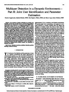
Fig. 8. This figure contrasts the transmitter chain used in the standard IEEE 802.11 implementation with the transmitter chain extended for dynamic OFDMA.
1
2
3
4
5 6 7 8 Number of terminals
9
10
11
12
Fig. 7. Proportion of assigned subcarriers for ebDA (left bar) and bDA (right bar) when stations move with a speed of 1 m/s obtained by simulation.
Assuming a speed of 10 m/s at a carrier frequency of 5.4 GHz, the channel coherence time computes to 1.25 ms [9]. Fig. 6 shows that for this example the runtime of aDA for more than 40 terminals exceeds the coherence time. bDA and ebDA only produce equal results if bDA uses a stable sorting algorithm, i.e., the order of equal elements is the same before and after sorting. Fig. 7 compares the assignments produced by bDA using Quicksort with those produced by ebDA. Due to the similarity of the results, we consider the achieved quality of both algorithms to be almost identical. C. Integrating dynamic OFDMA multiplexing After the scheduler has assigned the subcarriers to the stations, the access point must distribute the MAC frames for all receiving stations over the subcarriers according to the schedule. Dynamic OFDMA necessitates a multiplexer in the transmitter chain that performs this distribution. Fig. 8 compares the structure of a standard IEEE 802.11 transmitter chain with the one extended for dynamic OFDMA. In standard IEEE 802.11 as depicted in Fig. 8(a), the physical layer frame contains a single MAC frame for a single station, and the packet is spread over all subcarriers. In contrary, a physical
layer frame used in dynamic OFDMA contains several MAC frames that have been multiplexed such that the individual frame parts occupy the assigned subcarriers after mapping. Fig. 8(b) shows the corresponding transmitter chain for a three-user dynamic OFDMA. The MAC frames to be sent to the participating terminals are scrambled and convolutionally encoded one by one. The bitstreams representing the encoded frames are buffered until scrambling and encoding has been completed for all terminals. The multiplexer then combines the individual bitstreams into a single bitstream according to the subcarrier assignment. The mapper also uses the assignment to decide which modulation type is used on a specific subcarrier. The mapping is then fed into the IFFT, and the resulting OFDM symbols are passed to the RF frontend for analog processing. Note that for dynamic OFDMA the multiplexer supersedes the interleaver because typically a multiplexed frame of any station is distributed over the entire frequency band. Fig. 9 illustrates more precisely the principle of the multiplexer. The subcarrier assignment contains both terminal and modulation assignments. The multiplexer applies this assignment bitwise to the input streams supplied by the MAC sublayer. The modulation type specifies how many bits are mapped to any particular subcarrier, resulting in adaptive modulation. Since receiving terminals do not know the used assignment, our implementation stores the assignment as additional control information in the PLCP header. Since the PLCP header is always modulated using the most robust modulation type (BPSK with code rate R = 1/2), every station can demodulate it. After successful demodulation and decoding of the header, stations use the control information to demodulate the multiplexed MAC frame. Then, a demultiplexer restores the individual MAC frames, so that they can be passed on to the MAC sublayer. We successfully implemented the multiplexer and demultiplexer components of our dynamic OFDMA extension on the master DSP of S ORBAS. Fig. 10(a) motivates this decision. When the slave DSP executes the standard IEEE 802.11a physical layer, it requires up to twice the processing time of the master for a single OFDM symbol. An increase in
In Proc. 3rd Intl. Conf. on Testbeds and Research Infrastructures for the Development of Networks and Communities (TridentCom), May 2007 B
V. I MPLEMENTATION ISSUES AND TESTBED LIMITATIONS
MUX
Terminal 3 ... Terminal 2 ...
1
Terminal 1 ...
2
... Subcarriers
3
A C
Exemplary subcarrier assignment
Subcarrier
Terminal
Modulation
1 2 3
2 3 1
QPSK BPSK 16−QAM
A B C
...
...
Fig. 9. The multiplexer combines independent bitstreams according to the subcarrier assignment. The mapping of bits to symbols is called adaptive modulation.
Processing time per OFDM symbol [µs]
40 35 30
TX Master TX Slave RX Master RX Slave
25 20 15 10 5 0
BPSK 1/2
BPSK 3/4
QPSK 1/2
QPSK 3/4
16−QAM 2/3
16−QAM 3/4
Modulation types
(a) Runtime measurements of the standard IEEE 802.11a physical layer running on the master and slave DSPs for both transmitter and receiver.
Processing time per OFDM symbol [µs]
90 80
Multiplexer Demultiplexer
70 60 50 40 30 20 10 0
BPSK 1/2
BPSK 3/4
QPSK 1/2
QPSK 3/4
16−QAM 1/2
16−QAM 3/4
64−QAM 2/3
64−QAM 3/4
Modulation types
(b) Runtime measurements of our multiplexer and demultiplexer for all IEEE 802.11 modulation types when the same modulation type is used for all subcarriers. Fig. 10. Processing times per OFDM symbol for the standard IEEE 802.11a physical layer and the OFDMA multiplexer and demultiplexer.
processing time can be easier tolerated on the master DSP. Fig. 10(b) shows runtime measurements for the multiplexer and demultiplexer when a fixed modulation type is used for all subcarriers. The demultiplexer exhibits a runtime of at least twice the multiplexer. For code rates other than R = 1/2 puncturing is additionally required that contributes to the runtime.
The integration of dynamic OFDMA into the existing S ORBAS implementation of the IEEE 802.11a standard raised several issues and testbed limitations that need to be discussed. Although S ORBAS is a powerful prototyping testbed for wireless communications, these issues are significant as they either cause performance penalties or make certain implementations awkward. However, the latter point is mainly due to our decision to exclude both FPGAs from the integration to reduce development complexity. The separation of the physical layer into two parts that are distributed on two DSPs yields both advantages and disadvantages. A distributed design offers parallelization through pipelining as an advantage as the computational load can be equally distributed among the DSPs. The disadvantages are firstly owed to the synchronization between both DSPs. When chunks are transferred from one DSP to the other, the receiving DSP cannot operate on them until at least one chunk has been entirely received. Consequently, DSPs may have to wait for each other. Waiting times must be minimized to achieve high DSP utilization. Therefore, good code design for S ORBAS must achieve equal utilization of both DSPs to keep waiting times small. Secondly, global data must be exchanged between both DSPs. Every data exchange involves programming the DMA controller and interrupt handling when the DMA transfer completes. Such exchange contributes to the overall overhead of the implementation. S ORBAS does currently not provide an execution environment that abstracts from the hardware. Low-level functionality that is normally taken care of in execution environments or operating systems must be maintained by the developers themselves. This contributes considerably to the time required for development, especially for identifying errors. The provision of an execution environment for S ORBAS that abstracts from hardware would not only reduce development times, but would also increase the reusability of the software implementations. Wireless communication systems that achieve optimization by exploiting information from higher layers, so called crosslayer approaches like our dynamic OFDMA prototype, are problematic to be implemented solely on the DSPs. For our dynamic OFDMA implementation it is necessary to inspect MAC frames at the physical layer. For efficiency reasons, Viterbi decoding and descrambling are implemented on the FPGA that resides between the TigerSHARC DSPs executing the physical layer and the Blackfin DSP executing the MAC sublayer. As a consequence, the byte representation of the MAC frame is not available at the software running on the TigerSHARC DSPs. We were forced to replicate the desired bytes in the PLCP header. The PLCP header is the only part of the entire frame that is decoded on the slave DSP using a software Viterbi. Another daunting task in the implementation of cross-layer approaches is to distribute the required information between the involved layers in an efficient manner without causing significant control overhead and synchronization difficulties. Without adequate support of the hardware, working across
In Proc. 3rd Intl. Conf. on Testbeds and Research Infrastructures for the Development of Networks and Communities (TridentCom), May 2007 Convenient programming, but insufficient processing power.
Efficient implementation at the price of higher complexity.
FPGA
Hybrid SDR (SORBAS)
FPGA
FPGA
DSP
DSP
DSP
DSP−only SDR
Compro− mise
FPGA−only SDR
Fig. 11. The S ORBAS architecture is a compromise between the convenience offered by a pure DSP architecture and the performance offered by a pure FPGA architecture. This hybrid architecture exploits the advantages of both homogeneous designs, but it must also accept their disadvantages.
layers may necessitate awkward implementations. This problem becomes even more apparent when considering standard WLAN hardware available today, e.g., [19]. Physical layer and MAC are self-contained components, typically intellectual properties of different vendors that also inhibits to leverage the full power of cross-layer optimization. Adaptive modulation requires reliable signal to interference plus noise ratio (SINR) measurements. Although S ORBAS can determine the average signal strength in dBm of a received frame over frequency (averaged either over the frame’s preamble or its MAC part), in the current implementation it is not possible to directly measure interference plus noise over frequency when no packet arrives. The measurement is conducted on the slave DSP. The RF frontend only supplies data to the slave DSP if the observed RSSI value meets a configurable threshold and a valid OFDM PLCP preamble exists. Even though it is possible to lower the CCA threshold such that the RF frontend reacts upon interference plus noise, it will not detect a valid preamble and, consequently, no processing takes place on the slave DSP. Although currently no precise SINR measurement over frequency can be conducted, the RF frontend can be queried at any time for the current RSSI value. This enables at least measurements under the assumption of white noise. From an architectural point of view, the design of an SDR is a trade-off between convenience in programming and processing power. While a homogeneous DSP architecture can yield maximum convenience in terms of development, it suffers from limited performance. In contrast, a homogeneous FPGA architecture can provide maximum performance, but its implementation is more complex and involves larger development times. Fig. 11 illustrates this trade-off. S ORBAS combines both DSPs and FPGAs to enjoy the advantages of both homogeneous architectures, but it must then also accept their disadvantages as well. VI. C ONCLUSION We proposed a possible system design for integrating dynamic OFDMA functions into the IEEE 802.11a physical layer. Our extensions were designed to keep the delay of internal data flow within the IEEE 802.11a physical layer at a minimum, thereby reducing the overall transmission delay. This was achieved by improving, designing, and implementing fast rate adaptation, subcarrier allocation, and dynamic
OFDMA-capable multiplexing and demultiplexing. Low measured runtime shows the feasibility of these extensions. We further demonstrated that the selected subcarrier allocation algorithm provides results close to allocation methods that show high performance in simulations. Since the implementation is still work-in-progress, no performance measurements of the entire multiuser dynamic OFDMA integration are provided in this paper. We do not expect large negative effects on the theoretical performance gain with dynamic OFDMA since our extensions do not introduce significant overhead. Hence, we can conclude that our extension is a promising approach to let WLAN users benefit from the performance gain of dynamic OFDMA as shown in theoretical studies. While this paper mainly addressed the feasibility of dynamic OFDMA and the issues of a typical testbed, in future work we must assess the performance of our prototype. Based on our experience with implementing multiuser dynamic OFDMA on the S ORBAS IEEE 802.11 prototyping platform we conclude that this system is a productive environment for demonstrating the feasibility and for tackling implementation issues of theoretically well-studied communication techniques. Such rapid prototyping is not possible with off-theshelf hardware or through pure hardware development. Implementing IEEE 802.11 or even more complex future standards, e.g., IEEE 802.11n, on SDRs demands significant computation power which currently cannot be provided by simple hardware environments. This makes working with such prototyping systems non-trivial and introduces the demand for a hardware abstraction layer. With such an abstraction, e.g., as provided with the low-performance GNU software radio platform [20], the wireless system engineer can profit from the advantages of a high-performance rapid prototyping system, e.g., S ORBAS, while being relieved from time-intensive hardware-dependent development. Integrating such a hardware abstraction layer with a user-friendly API into complex wireless prototyping systems while keeping high performance is a demanding challenge in future testbed development. R EFERENCES [1] C. Y. Wong, R. S. Cheng, K. B. Letaief, and R. D. Murch, “Multiuser OFDM with adaptive subcarrier, bit, and power allocation,” IEEE J. Sel. Areas Commun., vol. 17, no. 10, pp. 1747–1758, Oct. 1999. [2] K.-D. Lee and V. C. M. Leung, “Fair allocation of subcarrier and power in an OFDMA wireless mesh network,” IEEE J. Sel. Areas Commun., vol. 24, no. 11, pp. 2051–2060, Nov. 2006. [3] Supplement to IEEE Standard for Information technology— Telecommunications and information exchange between systems—Local and metropolitan area networks—Specific requirements. Part 11: Wireless LAN Medium Access Control (MAC) and Physical Layer (PHY) specifications—High-speed Physical Layer in the 5 GHz Band, IEEE Std., Jul. 1999. [4] G. Holland, N. Vaidya, and P. Bahl, “A rate-adaptive MAC protocol for multi-hop wireless networks,” in Proc. 7th Annual International Conference on Mobile Computing and Networking (MobiCom), Jun. 2001, pp. 236–251. [5] J. Gross, H. Karl, F. Fitzek, and A. Wolisz, “Comparison of heuristic and optimal subcarrier assignment algorithms,” in Proc. International Conference on Wireless Networks (ICWN), Jun. 2003. [6] G. Li and H. Liu, “Resource allocation for OFDMA relay networks with fairness constraints,” IEEE J. Sel. Areas Commun., vol. 24, no. 11, pp. 2061–2069, Nov. 2006.
In Proc. 3rd Intl. Conf. on Testbeds and Research Infrastructures for the Development of Networks and Communities (TridentCom), May 2007 [7] J. Gross, J. Klaue, H. Karl, and A. Wolisz, “Cross-layer optimization of OFDM transmission systems for MPEG-4 video streaming,” Computer Commun., vol. 27, pp. 1044–1055, 2004. [8] J. Gross, S. Valentin, H. Karl, and A. Wolisz, “A study on the impact of inband signaling and realistic channel knowledge for an example dynamic OFDM–FDMA system,” Euro. Trans. Telecomms., vol. 16, no. 1, pp. 37–49, Jan. 2005. [9] J. Cavers, Mobile Channel Characteristics. Kluwer Academic, 2000. [10] Y. Xiao, “IEEE 802.11n: Enhancements for higher throughput in wireless LANs,” IEEE Wireless Commun., vol. 12, no. 6, pp. 82–91, Dec. 2005. [11] “SORBAS 101: Signalion software radio-based prototyping system,” Signalion GmbH, 2005. [Online]. Available: http://www.signalion.com/ [12] J. Mitola, “The software radio architecture,” IEEE Commun. Mag., vol. 33, no. 5, pp. 26–38, May 1995. [13] T. Shono, Y. Shirato, H. Shiba, K. Uehara, K. Araki, and M. Umehira, “IEEE 802.11 wireless LAN implemented on software defined radio with hybrid programmable architecture,” IEEE Trans. Wireless Communications, vol. 4, no. 5, pp. 2299–2308, Sep. 2005.
[14] M. Stege, T. Dräger, M. Henker, T. Hentschel, M. Hossmann, M. Löhning, C. Unger, A. Zoch, and G. Fettweis, “Hardware in a loop—A wireless communication system prototyping platform for IEEE 802.11n,” in Proc. 9th International OFDM-Workshop, Sep. 2004. [15] “Iperf 1.7.0 – The TCP/UDP bandwidth measurement tool,” University of Illinois, 2005. [Online]. Available: http://dast.nlanr.net/Projects/Iperf/ [16] B. Schmidt, “Implementing transmission rate adaptation in a software defined radio testbed for IEEE 802.11a wireless networks,” Bachelor thesis, University of Paderborn, Sep. 2006. [17] J. G. Proakis, Digital Communications. McGraw-Hill Higher Education, 2000. [18] D. Qiao and S. Choi, “Goodput enhancement of IEEE 802.11a wireless LAN link adaptation,” in Proc. IEEE International Conference on Communications (ICC), vol. 7, Jun. 2001, pp. 1995–2000. [19] ISL3890 – Wireless LAN Integrated Medium Access Controller with Baseband Processor, Intersil Americas Inc., Apr. 2003. [20] S. Valentin, H. von Malm, and H. Karl, “Evaluating the GNU software radio platform for wireless testbeds,” University of Paderborn, Tech. Rep., Feb. 2006.