... Access. Control (MAC) sublayer to leverage OFDMA advantages. We ... ^WT. AP. Fig. 1. Considered WLAN scenario with one Access Point (AP) transmitting.
This full text paper was peer reviewed at the direction of IEEE Communications Society subject matter experts for publication in the ICC 2008 proceedings.
Integrating multiuser dynamic OFDMA into IEEE 802.11 WLANs – LLC/MAC extensions and system performance Stefan Valentin, Thomas Freitag, and Holger Karl Computer Networks Group, University of Paderborn, Germany, {stefan.valentin|tf|holger.karl}@upb.de
Abstract— Multiuser dynamic OFDMA for the downlink has been extensively studied, specifically, in terms of fast close-tooptimal subcarrier allocation heuristics and the efficient representation of signaling information. Although these functions provide the fundament of dynamic OFDMA, a complete multiuser OFDMA system requires more functionality. Focusing on WLAN systems, we discuss such additional functionality required for enabling the IEEE 802.11 link and Medium Access Control (MAC) sublayer to leverage OFDMA advantages. We identify necessary extensions, study the resulting overhead, and introduce a lightweight design for a complete dynamic OFDMA IEEE 802.11a system. Studying its performance shows that with our lightweight integration dynamic OFDMA can improve IEEE 820.11a UDP throughput by up to 154% and UDP latency by up to 63% even if the full overhead is taken into account.
I. I NTRODUCTION Adapting wireless transmissions to the current channel situation can substantially improve network capacity [1]. With multiple users, multiple channels are present and their different states (multiuser diversity) can be exploited by appropriate channel allocation; in an OFDM multiple Access (OFDMA) downlink, it is even possible to do so at the level of Orthogonal Frequency Division Multiplexing (OFDM) subcarriers [2, 3]. Using this dynamic OFDMA subcarrier allocation to exploit multiuser diversity can increase network capacity proportionally to the logarithm of the number of users [4]. In practice, however, even optimal subcarrier allocation schemes cannot achieve this maximum capacity increase in real systems and varying wireless channels. One cause for this limitation is that realistic wireless channels are not necessarily Rayleigh distributed or uncorrelated [5, 6]. Further causes lie in the structure of dynamic OFDMA systems: First, strict time constraints for solving the subcarrier allocation problem (e.g. within a Logical Link Control (LLC) frame) and limited processing power demand feasible allocation heuristics. These heuristics should have low and predictable runtime but, at best, produce allocation decisions close to the optimum (without achieving it). Second, allocation algorithms need to know subcarrier states and require to transfer their decision to the receiver. Both results in significant communication overhead to exchange this so-called signaling1 information. 1 Here, the term signaling denotes exchanging control information and not defining physical signals.
These practical problems have been intensively explored by the research community resulting in feasible allocation heuristics [7–9], and efficient representations of the dynamic OFDMA-specific signaling information [10–12]. Although all these approaches are fundamental steps towards the implementation of dynamic OFDMA systems, a complete dynamic OFDMA system still requires more functionality. In this paper we discuss a complete integration of dynamic OFDMA into IEEE 802.11 Wireless Local Area Network (WLAN) systems; the goal is to improve the effective rate and latency at the application layer. In addition to subcarrier allocation and signaling, this integration requires new crucial functions at the IEEE 802.11 LLC and MAC. First, we propose an RTS/CTS-based MAC protocol extension for dynamic OFDMA signaling; unlike the above mentioned work our MAC protocol extension tackles the organization of the dynamic OFDMA signaling process rather than the representation of the signaling information. Second, we describe LLC functions for OFDMA fragmentation – a problem arising naturally when multiplexing large LLC frames on small sets of dynamically allocated subcarriers. This issue is not handled by existing fragmentation functions so far. Combining these MAC/LLC functions with a subcarrier allocation algorithm and an OFDMA Physical layer (PHY) results in a practicable design of a complete dynamic OFDMAcapable IEEE 802.11 system. We study the application layer performance of this system and analyze the effects of our MAC/LLC extensions. For this study, we exemplarily combine our extensions with a simple subcarrier allocation heuristic and an IEEE 802.11a OFDMA PHY [13]. Nonetheless, other heuristics, e.g. even performing bit- and power allocation, and other PHY designs are amenable to our techniques as well. Our simulation-based performance study considers the total overhead induced by dynamic OFDMA onto all IEEE 802.11a layers and does not omit side-effects. Comparable full layer performance studies were only done for IEEE 802.16 [14, 15] (where an OFDMA MAC and PHY is already standardized) but not for IEEE 802.11-based dynamic OFDMA systems. In Sec. II of this paper we introduce scenario and system assumptions. Details and overhead of our dynamic OFDMA IEEE 802.11 MAC and LLC extensions are discussed in Sec. III and IV, respectively. In Sec. V we study the system performance by simulation and Sec. VI concludes the paper.
978-1-4244-2075-9/08/$25.00 ©2008 IEEE
This full text paper was peer reviewed at the direction of IEEE Communications Society subject matter experts for publication in the ICC 2008 proceedings.
WT1
WT ^ ... J WTJ+1
AP WTJ
...
...
WT2 WT j
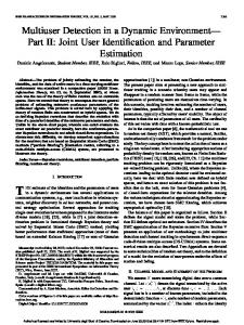
Fig. 1. Considered WLAN scenario with one Access Point (AP) transmitting to J out of Jˆ Wireless Terminals (WTs) in the same collision domain (called cell) via independent time and frequency selective fading channels.
II. S YSTEM MODEL A. Scenario assumptions We consider the simple WLAN infrastructure network with single antenna nodes illustrated in Fig. 1. Here, Jˆ IEEE 802.11 WTs are located around a single IEEE 802.11 AP in the center. The AP transmits control information and a specific, continuous User Datagram Protocol (UDP) packet stream (e.g. a large file) to J out of these Jˆ terminals. Despite this downlink transmission, only control information is assumed to be transmitted via the uplink from WT to AP. The channel model considers typical effects of terrestrial radio transmission. Specifically, interference, path loss and, due to multi-path propagation, frequency-selective fading are modeled. Within range of the AP each WT moves independently at velocity v. In addition to frequency-selective fading, this results in an independent time-selective fading channel per WT which we model by i.i.d. Rayleigh amplitudes and the “land mobile” autocorrelation function for isotropic antenna gain patterns (Table 2.1 in [6]). We assume non-reciprocal channels, meaning that the states of downlink and uplink channels are independent of each other. For the implementation of this model, we assume block fading with a specific fading coefficient per terminal, subcarrier, and coherence time block. B. OFDM and OFDMA physical layer assumptions All WLAN transceivers in the above scenario are based on the standard IEEE 802.11a OFDM PHY [16]. Hence, all PHY parameters comply with IEEE 802.11a, out of which 20 MHz signal bandwidth, Tsym = 4 µ s OFDM symbol time, S = 48 data subcarriers, 4 pilot subcarriers, and the 8 transmission modes each corresponding to 6, 9, 12, 18, 24, 36, 48 or 54 MBit/s PHY rate (depending on selected modulation and coding rate) are relevant for this paper. We assume constant transmission power, however, each WT employs a rate adaptation scheme [17] to select the PHY rate according to the measured channel state and a Packet Error Rate (PER) upper bound of 10% [16]. We assume that channel state measurement and rate adaptation is done at the receiver and that the selected rate is signaled to the transmitter where it is used for the next frame. Rate adaptation is only based on measuring the channel states over the Physical Layer Convergence Procedure (PLCP) preamble; no a-priori channel knowledge is assumed. As in standard IEEE 802.11a systems, only the 6 MBit/s mode of the OFDM PHY is employed for transmitting LLC control frames via up- and downlink. Depending on rate adaptation, any PHY rate can be chosen for data frames. On the downlink these data frames are transmitted using
either dynamic OFDMA or standard IEEE 802.11a OFDMTDD. With dynamic OFDMA, the dynamic OFDMA-extended IEEE 802.11a PHY described in [13] is used where each WT receives a subset of S j = S/J different subcarriers. In this PHY, rate adaptation is performed as above except that channel state is measured and PHY rate is adapted per subcarrier. Adapting subcarrier-wise only based on the PLCP preamble may be inaccurate with highly time and frequencyvariant fading channels. Here, further training sequences and pilots would improve adaptation accuracy but increase training overhead. Nonetheless, measurements have shown that in typical indoor and urban WLAN scenarios with low and medium mobility our above PLCP-based method suffices [13]. Using this method, the chosen PHY rate leads to either 0.5, 0.75, 1, 1.5, 2, 3, 4 or 4.5 uncoded data bits per subcarrier. The chosen number of bits per subcarrier is passed to the ebDA subcarrier allocation algorithm [13], i.e. a runtimeoptimized version of the basic Dynamic Algorithm (bDA) [9]. Both heuristics solve the subcarrier allocation problem simply by searching those S j subcarriers (out of the remaining free ones) providing the highest PHY rate for a WT. Rotating the WT indexes between the allocations avoids dominating WTs. The ebDA calculates the J × S allocation matrix N defining the allocated data bits for all S subcarriers and the J OFDMA terminals. While this calculation is typically 5% off the optimal solution [9], more sophisticated algorithms, e.g. even considering bit- and power allocation, may reach better performance. However, experiments on WLAN PHY prototypes have shown that its small and predictable runtime makes ebDA feasible for implementation [13]. Nevertheless, improved allocation algorithms can be easily integrated in our system. To show the potential performance gain in this case, we include optimal subcarrier allocation in our study. In addition to subcarrier allocation, dynamic OFDMA requires to flexibly map LLC data to OFDM subcarriers. With varying subcarrier allocations this mapping may change from frame to frame which requires dynamic frequency-division multiplexing at the AP and dynamic demultiplexing at each WT. We assume that this fundamental task is done by dynamic de/multiplexing functions which are part of an OFDMAextended IEEE 802.11a PHY and do not increase the latency of the complete transmission or reception process. More details on the implementation of these functions as well as runtime and performance measurements of an OFDMA-extended IEEE 802.11a transceiver prototype can be found in [13]. III. LLC EXTENSIONS FOR DYNAMIC OFDMA In this section, we discuss LLC extensions to support the transmission of multiple user data streams in a single OFDMA frame with varying subcarrier allocation. Fig. 2 illustrates these new functions and the resulting information flow between the LLC and PHY at the AP. A. Virtual queueing Unlike the standard IEEE 802.11 link layer the most multiuser OFDMA systems employ multiple queues at the AP, one
This full text paper was peer reviewed at the direction of IEEE Communications Society subject matter experts for publication in the ICC 2008 proceedings.
LLC Queueing
Fragmentation
PHY
WT1 LLC fragments Index queues ...
RF Parallel PHY processing
OFDM symbols
WTJ Allocation N Pointers
...
J Allocation N
Subcarrier eCTS allocation frames algorithm Subcarrier states
Fig. 2. Overview of the extended IEEE 802.11a transmission chain for the OFDMA downlink at the AP and of the data (solid lines) and control information (dashed lines) flow between LLC and PHY
for the LLC frames of each terminal. Although this simplifies separate scheduling for each terminal’s data, now the AP requires additional memory for each WT (e.g. to buffer an individual input rate peak for a WT). For easy integration and to decrease memory requirements as well as queue processing time, we propose to keep the single queue of IEEE 802.11 and separate it by index queues. Each of these index queues contains only small pointers to the LLC frames for a specific WT (Fig. 2). Instead of accessing it directly, the frame of a specific WT is accessed via the pointer of the respective index queue. In this paper we assume that each index queue is FIFO organized; an obvious extension is to integrate traffic-aware scheduling mechanisms here. B. LLC frame fragmentation Compared to a standard Physical Protocol Data Unit (PPDU) where all subcarriers are exclusively used by a single WT, OFDMA transmits LLC frames for several WTs simultaneously on different subcarriers. Here, each of these J WTs receives only a fraction of the bandwidth which, consequently, decreases the LLC payload in the PPDU for each WT. This reduces the maximum size of the link layer packets, called Maximum Transmission Unit (MTU), and increases overhead due to more transmitted packet headers. A more serious problem is that the duration of LLC frames may differ within a single OFDMA PPDU. This results from unequal PHY rates for the WTs as a consequence of the current subcarrier allocation. Fig. 3(a) shows an example: WT 1 is assigned better subcarriers and, thus, a higher PHY rate than WT 2 and 3 with bad subcarriers; assume all WTs use the same LLC frame length. The higher rate allows WT 1 to finish its transmission earlier than WT 2 and 3, but it has to wait for the slower WTs 2 and 3. During this waiting time its assigned subcarriers are idle and, therefore, wasted. One option to handle this problem would be to integrate fairness constraints into the subcarrier assignment algorithm, trying to achieve a uniform bandwidth allocation for all WTs [4]. However, this increases the computational complexity of this algorithm (which is already a highly timecritical component) and it limits its optimization options. As an alternative, light-weight solution, we propose a frame fragmentation scheme at the LLC. First, fragmenting at the LLC allows a large MTU, hence, making OFDMA transparent
WT3
low PHY rate
WT2
low PHY rate
WT3
S =16
S =24
S =0
high PHY rate
WT2
S =16
S =24
S =48
WT1
Min. fragment time Tfr
wasted Time
(a) Wasted transmission time within OFDMA PPDU
WT1
3
2
S =16 1
PPDU 1
3 2
S =0 1
PPDU 2
1
2
S =0 1
PPDU 3 Time
(b) Fragmentation cycle for three WTs with increasing S j over time
Fig. 3. Examples for wasted transmission time within an OFDMA PPDU and its avoidance by fragmentation and fragment time (Tfr ) selection
to the higher layers. Second, and even more important, our fragmentation scheme eliminates wasting transmission time by suitably selecting the fragment lengths of different terminals. This selection depends on the current subcarrier allocation matrix N and, thus, feedback from the subcarrier allocation algorithm (Fig. 2) but does not need to modify this algorithm. Our fragmentation scheme is based on two core ideas both illustrated in Fig. 3(b). First, we let the fastest WT (best subcarriers) define the duration of all fragments per PPDU. Within each OFDMA PPDU this results in equal duration for all fragments eliminating wasted transmission time. The second basic idea is to reduce signaling overhead by avoiding to collect new subcarrier states from the terminals between the transmission of fragments. Instead, re-allocations of subcarriers are calculated based on the original subcarrier states obtained at the start of a fragmentation cycle (for details, see Sec. IV). These subcarriers could be used at full rate as calculated at the start of the cycle or the rate could be reduced. The full rate shortens the fragment duration (increasing transmission rate) but runs the risk of using the subcarriers at rates which are too high to transmit reliably. At reduced rate, the additional subcarriers could be used to compensate for deteriorated subcarriers (frequency diversity). Here, the fragment duration is longer than with the first option, actually increasing the risk of using out-of-date subcarrier information. Therefore, we follow the first, more aggressive option which performs well in our simulations (Sec. V). In the first step, our fragmentation scheme defines the duration of the OFDMA PPDU, valid for all WTs; it is called fragment time Tfr . Based on the fragment time the length Lfr, j of the fragment (number of bits) for each WT j = 1, . . . , J is derived individually. Initially, we define the fragment lengths for all WTs to be Lfr, j := L f /J bits dividing length L f of a normal LLC frame (e.g. defined by the MTU) by J to meet the duration of a standard PPDU. Based on Lfr, j we calculate the transmission time individually for each WT j as T j = Lfr, j /R j , where Sj R j = ∑s=1 N j,s /Tsym denotes the PHY rate (in bits/s) of WT j resulting from its S j subcarriers. Here, N j,s refers to an element in the current allocation matrix defining j’s number of uncoded data bits at subcarrier s per OFDM symbol. Based on the individual transmission time T j , the fragmentation scheme can now select the overall fragment time as the minimum over all transmission times Tfr := min∀J T j . Finally, for each of the J WTs the fragment length used in this PPDU
This full text paper was peer reviewed at the direction of IEEE Communications Society subject matter experts for publication in the ICC 2008 proceedings.
is individually defined as Lfr, j := Tfr R j . After all fragment lengths are chosen, the LLC frames are split into fragments and transmitted within a single OFDMA PPDU. While with this method the fragment lengths may differ between the J LLC frames, all frames within an OFDMA PPDU are of equal fragment time Tfr and no transmission time is wasted. Furthermore, it is assured that at least one, possibly several WTs transmit a complete frame per OFDMA PPDU. In the second step, we exclude those WTs with completed frames from the subsequent PPDUs. By re-assigning the subcarriers of the excluded WTs, the subcarrier number S j for the remaining WTs increases (Fig. 3(b)). This assignment is not based on new subcarrier states but requires to calculate a new subcarrier allocation. Based on these new subcarrier assignments, Lfr, j is recalculated as above except that it is not initialized by the standard frame length but instead represents the remaining bits each terminal has to send to complete its frame. Since, again, the shortest fragment time defines Tfr for this PPDU, no time of the PPDU transmission is wasted during transmission. This procedure is repeated until all fragments and, thus, J complete LLC frames (one for each WT) are transmitted. Then the next fragmentation cycle starts by performing a new eRTS/eCTS cycle (Sec. IV), calculating a new subcarrier allocation, and processing the new LLC frames of all participating WTs. The fragmentation scheme is also integrated with the ACK procedure (Sec. IV); ACKs are sent after each PPDU for each fragment individually. It is possible, then, that no ACKs arrive for those fragments that would complete a terminal’s frame. Based on individual retry counters per WT, the fragmentation scheme is robust to such a situation and simply retransmits these fragments again. Our fragmentation scheme calculates its fragment length based on the current subcarrier allocation. How these allocations and subcarrier states are signaled between AP and WTs and how medium access is organized during the transmission of multiple fragments is discussed in the following section. IV. E XTENDING RTS/CTS MAC FOR DYNAMIC OFDMA To support dynamic OFDMA, an IEEE 802.11-based MAC sublayer has to 1) invoke subcarrier state measurements at the WTs, 2) transport the measurement results back to the access point for subcarrier allocation, 3) provide information to the WTs which terminal has to receive at which time and over which subcarriers, and 4) integrate the fragmentation process described in Sec. III into the MAC procedure. In an AP-based scenario, it might be possible to include such signaling information purely into DATA and ACK frame as follows: Terminals measure subcarriers from received DATA frames and signal their state back via ACKs. But terminals are unlikely to receive a packet in each (frequency multiplexed) DATA frame, either because there is no backlogged data for them or because of the limited scaling properties of OFDMA (too many terminals included in one DATA frame would not pay off). Then, the subcarrier states at the AP would usually be out of date and useless. Alternatively, the
AP
WT1
WT2
AP
RTS
WT1
WT2
eRTS
SIFS
SIFS
CTS
eCTS
SIFS
SIFS
DATA1
eCTS SIFS
SIFS ACK
DATA2(F1) DATA1(F1)
Contention + DIFS SIFS
RTS ACK
SIFS
SIFS ACK
CTS
SIFS
SIFS DATA2(F2)
DATA2
SIFS
SIFS ACK
(a) Two RTS/CTS cycles for standard transmission
ACK
(b) One eRTS/eCTS cycle for dynamic OFDMA
Fig. 4. Example MSCs of standard and extended RTS/CTS cycle(s) required to transmit a single LLC frame each to two WTs
above requirements lend themselves to be incorporated into IEEE 802.11’s RTS/CTS exchange. This section discusses such an appropriate extension to RTS/CTS, the required control frame modifications, and the resulting overhead. We explain the differences between the standard RTS/CTS cycle and our OFDMA-extended RTS/CTS scheme (eRTS/ eCTS for short)2 using the example of Fig. 4; here, the AP transmits a single LLC frame to each of two WTs. Standard IEEE 802.11 needs two independent, sequential RTS/CTS cycles (Fig. 4(a)). The eRTS/eCTS scheme supports the simultaneous OFDMA broadcast of both frames in the two transmitted LLC fragments (Fig. 4(b)). The extended cycle starts with an eRTS frame sent by the access point. It contains the MAC addresses of the J WTs to be included in the cycle. The eRTS triggers these terminals to measure subcarrier state; it is therefore sent at a standard transmission power and always at lowest PHY rate. Based on this measurement, each WT determines, for each subcarrier, the highest possible transmission rate for this subcarrier. A triggered terminal that does not correctly receive the eRTS simply does not participate in this cycle. Each triggered terminal answers with an eCTS frame, containing the selected rates per subcarrier. To prevent collisions of these frames, each WT delays its eCTS by a time determined by the order of the MAC addresses in the eRTS frame: The WT whose MAC address appears at position i in this list delays sending its eCTS by i · SIFS + (i − 1)TeCTS seconds, where TeCTS is the time to sent an eCTS (cf. Fig. 4). Since this list is known to all WTs (eRTS broadcast) and TeCTS is constant for all terminals, eCTS collisions do not occur in typical WLAN scenarios (with a cell radius below a few kilometers). A WT failing to receive the eRTS obviously does 2 Legacy terminals would simply ignore these extended frames and could thus easily be integrated.
This full text paper was peer reviewed at the direction of IEEE Communications Society subject matter experts for publication in the ICC 2008 proceedings.
Bytes 2
2
6
6
Frame Destination Control Duration Address 1
...
6
4
Bytes 2
(a) eRTS frame Bits 4 1
12
2
6
18
4
Frame Destination Control Duration Address Subband modes FCS
Destination Source Address J Address FCS
(b) eCTS frame 1
6
Rate 1 Length P Tail Bits
6 J
0...288 WT Subc.1
...
WT Subc.S Pad Bits
(c) ePLCP header Fig. 5. Extended IEEE 802.11 RTS/CTS (eRTS/eCTS) and extended IEEE 802.11a PLCP (ePLCP) header as used for dynamic OFDMA signaling
not send an eCTS, wasting some limited amount of time here. After the AP has received all eCTS frames, all subcarrier transmission rates are available to calculate the allocation matrix N. While calculating subcarrier allocation based on received signal strength or Signal-to-Noise Ratio (SNR) may be more accurate than using rates, signaling this fine-grained subcarrier state information to the AP significantly increases transmission overhead. Our performance results do not justify this higher overhead. During subcarrier allocation, WTs from which no eCTS has been received are ignored until the next eRTS/eCTS cycle. The calculation has to be performed within a single Short Inter-Frame Space (SIFS) time. While this is no problem with, e.g., the ebDA heuristic [13], this timing bound might be too strict for more sophisticated allocation algorithms. In this case, longer delays than a single SIFS or more powerful processing hardware may be required. The AP proceeds by fragmenting the LLC frames for all J WTs according to the current subcarrier allocation (Sec. III) and transmits, an SIFS after the last eCTS, the first fragment for each WT (F1 in Fig. 4(b)). At the beginning of a fragment, a single extended PLCP (ePLCP) header is transmitted at the lowest PHY rate over all subcarriers and signals the allocated subcarriers and transmission rates to each WT. Each WT demodulates the ePLCP, determines its assigned subcarriers for its payload, and receives its first LLC fragment. If the fragment was received correctly, an ACK frame is transmitted. To avoid ACK collisions, ACK delays are calculated as for eCTS. After the first fragments are acknowledged, the transmission cycle proceeds by transferring the remaining fragments as well as fragments with an outstanding ACK (Sec. III). Since in this next PPDU typically fewer terminals participate, the subcarriers are reassigned and re-signaled again in the ePLCP of the next fragments. Also, this assignment allows the remaining WTs to adjust their ACK delays to avoid waiting for ACKs from the excluded WTs; the original order of the eRTS is still used. Transmitting remaining fragments and adjusting control frame delays is repeated until the last remaining fragment is acknowledged. After that, the next eRTS/eCTS cycle starts. The above signaling protocol uses eRTS/eCTS MAC control frames and an extended PLCP header at the PHY to transfer dynamic OFDMA signaling information. Fig. 5 shows all these frames; the data fields added to the standard frames are shaded. The eRTS contains all J MAC addresses of the participating WTs and varies its size in order of J. Each WT employs
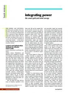
an eCTS for signaling the selected transmission rate of all S subcarriers to the AP. With the 48 data subcarriers and 8 transmission modes of IEEE 802.11a this adds an 18 Byte mode field to the CTS. Both control frames are transmitted using the standard IEEE 802.11a OFDM PHY at lowest rate (6 Mbit/s) resulting in a transmission time between 28 and 404 µ s for the eRTS (between 1 and, unrealistically, 48 terminals) and of 48 µ s for the eCTS. The subcarrier allocations included in the ePLCP headers allow the WTs to only demultiplex and demodulate from the allocated subcarriers which significantly decreases PHY complexity [13]. As shown, the ePLCP can be simply constructed by appending one WT index per subcarrier. Depending on the current J this results in a signaling field of variable size S log2 (J) = [0, 288] bits. The complete ePLCP header is transmitted in 1 to 13 OFDM symbols at the lowest rate of the standard PHY; it is sent once per fragmentation cycle. In summary, the dynamic OFDMA signaling overhead linearly increases in the number of WTs participating per eRTS/eCTS cycle. This naturally results from IEEE 802.11a’s constant number of subcarriers and transmission modes. To provide an effective performance increase, a dynamic OFDMA IEEE 802.11a system has to provide gains exceeding this overhead. In which cases this is possible is studied in the following section. V. S YSTEM PERFORMANCE STUDY We now study under which conditions users benefit from integrating dynamic OFDMA into IEEE 802.11. For this study, we compare the downlink transport layer performance of our proposed system to standard IEEE 802.11a. All results are obtained by simulation. Our simulator incorporates models for a complete dynamic OFDMA IEEE 802.11a system including the MAC/LLC extensions proposed in this paper and the OFDMA PHY proposed in [13]. We parameterize the channel model according to an indoor environment by choosing an RMS delay spread of 150 ns, maximum WT velocity of 1 m/s, zero-mean lognormal shadowing with σ = 5.8 dB, a noise floor of −117 dBm per subcarrier, and a path loss exponent of 2.8 [18]. Furthermore, we choose a center frequency of 5.2 GHz, an MTU of 1500 Bytes, and traffic generation rates saturating the links. All remaining LLC and PHY parameters are chosen as in standard IEEE 802.11a. We study different numbers of J destination WTs participating in the OFDMA protocol cycles. For all results, confidence intervals are not shown due to their small sizes (at 95 % level). In our study, we first focus on the total UDP rate to all J WTs within a single cell around the AP (Fig. 1). This rate represents the sum over all J destination WTs and is called cell goodput since it takes errors and LLC retransmissions into account. Fig. 6 shows mean cell goodput for various J. Even for a single terminal the dynamic OFDMA systems show a large benefit compared to standard IEEE 802.11a. This large goodput gain cannot result from subcarrier allocation since with a single terminal no multiuser diversity gain can be exploited. Instead, it results from the subcarrier-based
This full text paper was peer reviewed at the direction of IEEE Communications Society subject matter experts for publication in the ICC 2008 proceedings.
3.5e+07
3.5e+07 Standard, 11 dBm Dynamic OFDMA, ebDA, 11 dBm Dynamic OFDMA, optimal, 11 dBm Standard, -9 dBm Dynamic OFDMA, ebDA, -9 dBm Dynamic OFDMA, optimal, -9 dBm
2.5e+07
Standard, J=4 Dynamic OFDMA, ebDA, J=4 Dynamic OFDMA, optimal, J=4
3e+07 Mean cell goodput [Bit/s]
Mean cell goodput [Bit/s]
3e+07
2e+07 1.5e+07 1e+07
2.5e+07
2e+07
1.5e+07
1e+07
5e+06 0 0
5
10
15
20
25
Number of destination WTs J
5e+06 -10
-5
0
5
10
15
Transmission power [dBm]
Fig. 6. Mean cell goodput vs. number of destination WTs J for the downlink transmission of a standard and OFDMA-extended IEEE 802.11a WLAN with heuristic (ebDA) or optimal subcarrier allocation and Ptx = 11 or −9 dBm.
Fig. 7. Mean cell goodput vs. transmission power (Ptx ) for the downlink transmission of a standard and OFDMA-extended IEEE 802.11a WLAN with heuristic (ebDA) or optimal subcarrier allocation
rate adaptation of dynamic OFDMA. With frequency-selective fading, choosing the PHY rate per subcarrier is clearly more accurate than subcarrier-mean-based rate adaptation as performed by typical IEEE 802.11a systems. This large gain, also observable for J > 1, is called rate adaptation gain. While for standard IEEE 802.11a the cell goodput only slightly changes with varying J, a significant effect vs. J is shown for dynamic OFDMA. The mean cell goodput increases logarithmically in J until a specific number of WTs is reached. This logarithmic increase corresponds to theoretical results [4] and is specific for systems exploiting multiuser diversity by subcarrier allocation. The absolute goodput and the relative gain depend on the chosen allocation strategy and, obviously, are highest in a system where optimal subcarrier allocation is performed (but where signaling overhead and LLC/MAC extensions are considered). Compared to standard IEEE 802.11a, optimal subcarrier allocation shows a maximum possible cell goodput gain by 154% with dynamic OFDMA for 4 WTs at 11 dBm transmission power. At this point, the simpler ebDA heuristic reaches 103% gain. Here, even with ebDA exploiting multiuser diversity results in a significant gain up to a specific number of WTs. Beyond this J-threshold, the goodput of all studied dynamic OFDMA systems decreases. This results from the different orders of the costs and benefits of our dynamic OFDMA system. While the overhead increases linearly with the number of terminals J (Sec. IV) the achieved multiuser diversity gain increases only logarithmic in J. Hence, for large J dynamic OFDMA cannot compensate for the increased overhead by exploiting multiuser diversity. While this is the case for all studied subcarrier allocation schemes it is less severe for the optimal scheme. Here, even for larger J a high multiuser diversity gain can be reached which results in a smaller decrease over J than with ebDA. For increasing J, ebDA’s goodput decreases faster until (for J = 24) even the large rate adaptation gain is used up and only goodput comparable to the standard system is reached. A further gain, not depending on J, results from the two dif-
ferent values studied for the transmission power (Ptx ). Lower Ptx decreases the SNR, i.e. degrades the subcarrier states. First, this decreases the PHY rate for each WT and, hence, the goodput of all studied cases. Second, specific for dynamic OFDMA, decreasing Ptx significantly decreases the Degree of Freedom (DoF) for allocating subcarriers due to the smaller variance between the subcarrier states. This decreases the diversity gain subcarrier allocation can reach and is illustrated by the decreased slope from J = 1 to 4 at −9 dBm (Fig. 6). Fig. 6 has shown J = 4 as the best operating point of our system for two different transmission power values. We now study this operating point for varying Ptx by looking at mean cell goodput (Fig. 7). The largest goodput increase, compared to standard IEEE 802.11a, can be found in the low and medium Ptx range. Here, optimal subcarrier allocation increases goodput by up to 130% and even ebDA reaches a gain of 87% (−3 dBm). Naturally, with rising Ptx the absolute goodput increases due to higher selected PHY rates and decreased Frame Error Rate (FER). However, this is also the case for standard IEEE 802.11a, resulting in a smaller relative goodput increase for dynamic OFDMA. Nevertheless, even with high Ptx , significant goodput increases can be reached. Fig. 8 shows the mean delay of a single UDP packet for varying Ptx . This metric behaves similarly to goodput. While large relative performance increases can be found for low and medium Ptx (63% for optimal and 54% for ebDA at −9 dBm) the performance of all systems converges with larger Ptx . As with very low Ptx , also very high Ptx limits the DoF for solving the subcarrier allocation problem. High Ptx results in permanently high PHY rate for all subcarriers reducing the channel state variance and, thus, decreasing dynamic OFDMA gain. Nonetheless, even in terms of packet delay our dynamic OFDMA-capable IEEE 802.11a significantly benefits from subcarrier allocation and subcarrier-based rate adaptation. Finally, we study the mean number of LLC fragments our proposed fragmentation scheme requires to transmit a single UDP packet. As shown in Fig. 9, for each studied Ptx optimal subcarrier allocation significantly decreases fragmentation
This full text paper was peer reviewed at the direction of IEEE Communications Society subject matter experts for publication in the ICC 2008 proceedings.
0.026 Standard, J=4 Dynamic OFDMA, ebDA, J=4 Dynamic OFDMA, optimal, J=4
0.024
Mean packet delay [s]
0.022 0.02 0.018 0.016 0.014 0.012 0.01 0.008 0.006 0.004 -10
-5
0
5
10
15
Transmission power [dBm]
R EFERENCES
Fig. 8. Mean UDP packet delay vs. transmission power (Ptx ) for the downlink transmission of a standard and OFDMA-extended IEEE 802.11a WLAN with heuristic (ebDA) or optimal subcarrier allocation
Standard, J=4 Dynamic OFDMA, ebDA, J=4 Dynamic OFDMA, optimal, J=4
Mean no. of fragments per UDP packet
1.8 1.7 1.6 1.5 1.4 1.3 1.2 1.1 1 -10
-5
0
5
terminals, and the consequently varying degree of concurrency during a packet cycle. These problems were solved by introducing a fragmentation scheme at the link sublayer taking the current subcarrier allocation into account. Overall, we increase UDP throughput of standard IEEE 802.11a by up to 103% with realistic system complexity and by up to 154% with more complex subcarrier allocation algorithms. First, these results strongly motivate to study further WLAN scenarios, e.g. including legacy terminals. Second, the proposed mechanisms already make it possible to integrate dynamic OFDMA in real-world WLAN implementations, allowing everybody to benefit from multiuser diversity.
10
Transmission power [dBm]
Fig. 9. Mean number of fragments per UDP packet vs. transmission power (Ptx ) for the downlink transmission of a standard and OFDMA-extended IEEE 802.11a WLAN with heuristic (ebDA) or optimal subcarrier allocation
compared to ebDA and requires only a single OFDMA transmission for Ptx > 1 dBm. This results from the rate fairness of optimal subcarrier allocation (each WT receives comparable subcarriers and, thus, PHY rate) which avoids significantly different PHY rates in advance. In our proposed system, rate fairness directly results in goodput increases since overhead due to fragmentation and long eRTS/eCTS cycles is reduced. VI. C ONCLUSION This paper has addressed the problem of designing a MAC and link sublayer for integrating and exploiting dynamic OFDMA subcarrier allocation in IEEE 802.11 WLANs. The first challenge was to find efficient mechanisms supporting the necessary information exchange between access points and wireless terminals such that the Physical layer (PHY) benefits are not lost by link/MAC sublayer mechanisms. The RTS/CTS mechanism and the PLCP PHY frame header turned out to be amenable to such an extension and realized the theoretical gains effectively at the MAC sublayer. Further non-trivial problems were the fragmentation of packets, caused by the different PHY rates for different
[1] P. Bhagwat, P. Bhattacharya, A. Krishna, and S. K. Tripathi, “Enhancing throughput over wireless LANs using channel state dependent packet scheduling,” in Proc. Ann. Joint Conf. of the IEEE Computer Societies (INFOCOM), vol. 3, 1996, pp. 1133–1140. [2] C. Y. Wong, R. S. Cheng, K. B. Letaief, and R. D. Murch, “Multiuser OFDM with adaptive subcarrier, bit, and power allocation,” IEEE J. Sel. Areas Commun., vol. 17, no. 10, pp. 1747–1758, Oct. 1999. [3] W. Rhee and J. M. Cioffi, “Increase in capacity of multiuser OFDM system using dynamic subchannel allocation,” in Proc. Vehicular Technology Conf. (VTC-Spring), vol. 2, May 2000, pp. 1085–1089. [4] G. Song and Y. Li, “Cross-layer optimization for OFDM wireless networks – part I: theoretical framework,” IEEE Trans. Wireless Commun., vol. 4, no. 2, pp. 614–624, Mar. 2005. [5] P. Viswanath, D. Tse, and R. Laroia, “Opportunistic beamforming using dumb antennas,” IEEE Trans. Inf. Theory, vol. 48, no. 6, pp. 1277–1294, Jun. 2002. [6] M. K. Simon and M.-S. Alouini, Digital Communications over Fading Channels, 2nd ed. John Wiley & Sons, Inc., 2004. [7] G. Song and Y. Li, “Cross-layer optimization for OFDM wireless networks – part II: algorithm development,” IEEE Trans. Wireless Commun., vol. 4, no. 2, pp. 625–634, Mar. 2005. [8] K.-D. Lee and V. Leung, “Fair allocation of subcarrier and power in an OFDMA wireless mesh network,” IEEE J. Sel. Areas Commun., vol. 24, no. 11, pp. 2051–2060, Nov. 2006. [9] J. Gross, H. Karl, F. Fitzek, and A. Wolisz, “Comparison of heuristic and optimal subcarrier assignment algorithms,” in Proc. Int. Conf. on Wireless Netw. (ICWN), Jun. 2003. [10] H. Nguyen, J. Brouet, V. Kumar, and T. Lestable, “Compression of associated signaling for adaptive multi-carrier systems,” in Proc. Vehicular Technology Conf. (VTC-Spring), vol. 4, May 2004, pp. 1916–1919. [11] J. Gross, S. Valentin, H. Karl, and A. Wolisz, “A study on the impact of inband signaling and realistic channel knowledge for an example dynamic OFDM-FDMA system,” Euro. Trans. Telecomms., vol. 16, no. 1, pp. 37–49, Jan. 2005. [12] J. Gross, H.-F. Geerdes, H. Karl, and A. Wolisz, “Performance analysis of dynamic OFDMA systems with inband signaling,” IEEE J. Sel. Areas Commun., vol. 24, no. 3, pp. 427–436, Mar. 2006. [13] H. S. Lichte, S. Valentin, F. Eitzen, M. Stege, C. Unger, and H. Karl, “Integrating multiuser dynamic OFDMA into IEEE 802.11a and prototyping it on a real-time software-defined radio testbed,” in Proc. TridentCom, May 2007. [14] M. Einhaus, O. Klein, B. Walke, and R. Halfmann, “Simulative MAC level performance evaluation of an OFDMA system under the consideration of frequency correlated fading,” in Proc. IEEE Wireless Commun. and Netw. Conf. (WCNC), Mar. 2007, pp. 411–416. [15] H. Jia, Z. Zhang, G. Yu, P. Cheng, and S. Li, “On the performance of IEEE 802.16 OFDMA system under different frequency reuse and subcarrier permutation patterns,” in Proc. IEEE Int. Conf. on Commun. (ICC), Jun. 2007. [16] B. O’Hara and A. Petrick, IEEE 802.11 Handbook: A designers companion. IEEE Press, 1999. [17] G. Holland, N. Vaidya, and P. Bahl, “A rate-adaptive MAC protocol for multi-hop wireless networks,” in Proc. Ann. Int. Conf. on Mobile Computing and Networking (MobiCom), Jun. 2001, pp. 236–251. [18] J. Medbo and P. Schramm, “Channel models for HIPERLAN/2,” ETSI EP BRAN 3ERI085B, Mar. 1998.