May 12, 1998 - D Integration of Distributed Generation into the Market Structure. 121 ... D.2 Distributed Generation in Spot Energy and Services Markets . . . . . . . . . . . . . 122. D.2.1 ...... [33] Chitru Fernando, Paul Kleindorfer, Richard D. Tabors, Fred Pickel, and Sandra J. Robinson. .... [77] Leonard Lublin and Michael Athans.
Integrating Small Scale Distributed Generation into a Deregulated Market: Control Strategies and Price Feedback Judith Cardell
Marija Ili´c
Richard D. Tabors Laboratory for Electromagnetic and Electronic Systems Massachusetts Institute of Technology
for: US Department of Energy, Office of Utility Technologies May 12, 1998
Abstract Small scale power generating technologies, such as gas turbines, small hydro turbines, photovoltaics, wind turbines and fuel cells, are gradually replacing conventional generating technologies, for various applications, in the electric power system. The industry restructuring process in the United States is exposing the power sector to market forces, which is creating competitive structures for generation and alternative regulatory structures for the transmission and distribution systems. The potentially conflicting economic and technical demands of the new, independent generators introduce a set of significant uncertainties. What balance between market forces and centralized control will be found to coordinate distribution system operations? How will the siting of numerous small scale generators in distribution feeders impact the technical operations and control of the distribution system? Who will provide ancillary services (such as voltage support and spinning reserves) in the new competitive environment? This project investigates both the engineering and market integration of distributed generators into the distribution system. On the technical side, this project investigates the frequency performance of a distribution system that has multiple small scale generators. Using IEEE sample distribution systems and new dynamic generator models, this project develops general methods for ensuring system stability. One such method is to specify ranges, or standards, for governor settings which will ensure local frequency stability. With respect to the emerging competitive markets, this project develops a price-based control concept which allows independent generators to participate in both the energy and the services markets, with minimal constraints from a central authority. In particular, a closed loop price signal is designed to operate in a competitive market and facilitate desired energy transactions without depending upon the extensive information and centralized control structure of the traditional power system. This project simulates the use of the price signal, and demonstrates its ability to coordinate generator actions in the competitive market while also maintaining the desired level of system reliability and stability. The policies developed during the industry restructuring process, and the extent to which these policies open the emerging markets to distributed generators, will impact the penetration of distributed generators in the distribution system and their ability to participate in the competitive markets. In particular, state polices which constrain distributed generators to be owned by local distribution utilities will prevent these generators from becoming equal players in the competitive markets. Alternatively, retail competition may encourage an increased use of distributed generators. A closed loop price signal, as proposed here, is an important element of the industry restructuring process because it promotes the development of competitive markets and the full integration of distributed generators into these markets.
Contents Executive Summary
5
Operation and Control of Distributed Generation
21
0.1
Introduction . . . . . . . . . . . . . . . . . . . . . . . . . . . . . . . . . . . . . . . . . 21
0.2
Technical Issues for Distributed Generation . . . . . . . . . . . . . . . . . . . . . . . 22
0.3
0.2.1
Distribution System Characteristics . . . . . . . . . . . . . . . . . . . . . . . 23
0.2.2
Developing a Dynamic System Model . . . . . . . . . . . . . . . . . . . . . . 24
0.2.3
Sample Distributed Generation Systems . . . . . . . . . . . . . . . . . . . . . 26
0.2.4
Sources of System Instability . . . . . . . . . . . . . . . . . . . . . . . . . . . 29
0.2.5
Methods for Stabilizing the System . . . . . . . . . . . . . . . . . . . . . . . . 30
0.2.6
Summary . . . . . . . . . . . . . . . . . . . . . . . . . . . . . . . . . . . . . . 32
System Coordination in a Competitive Market . . . . . . . . . . . . . . . . . . . . . 32 0.3.1
The Energy and Services Markets
. . . . . . . . . . . . . . . . . . . . . . . . 33
0.3.2
Objectives of the Closed Loop Price Signal . . . . . . . . . . . . . . . . . . . 33
0.3.3
The Role of the Closed Loop Price Signal in the Market . . . . . . . . . . . . 34
0.3.4
Anticipated Generator Response to Price Feedback . . . . . . . . . . . . . . . 35
0.3.5
Developing The Closed Loop Price Signal Model . . . . . . . . . . . . . . . . 37
0.3.6
Simulations of Competitive Market Operation . . . . . . . . . . . . . . . . . . 40
0.3.7
Base Case – Competitive Market . . . . . . . . . . . . . . . . . . . . . . . . . 40
0.3.8
Non-Dispatchable Technologies: Wind Turbines . . . . . . . . . . . . . . . . . 41
0.3.9
Imperfect Information: Uncertainty
. . . . . . . . . . . . . . . . . . . . . . . 43
0.4
Conclusions . . . . . . . . . . . . . . . . . . . . . . . . . . . . . . . . . . . . . . . . . 44
0.5
Overview of Appendices . . . . . . . . . . . . . . . . . . . . . . . . . . . . . . . . . . 45
2
CONTENTS
A Operations and Control Framework for Distributed Technologies
48
A.1 Introduction . . . . . . . . . . . . . . . . . . . . . . . . . . . . . . . . . . . . . . . . . 48 A.2 Distributed Generator Characteristics . . . . . . . . . . . . . . . . . . . . . . . . . . 49 A.2.1 Existing Uses of Distributed Generation . . . . . . . . . . . . . . . . . . . . . 49 A.2.2 Dispatchable Technologies . . . . . . . . . . . . . . . . . . . . . . . . . . . . . 49 A.2.3 Non-Dispatchable Technologies . . . . . . . . . . . . . . . . . . . . . . . . . . 51 A.3 The Transmission and Distribution Systems . . . . . . . . . . . . . . . . . . . . . . . 54 A.3.1 Physical Differences . . . . . . . . . . . . . . . . . . . . . . . . . . . . . . . . 54 A.3.2 Load Shape and Peak Coincidence . . . . . . . . . . . . . . . . . . . . . . . . 56 A.4 Lessons from Transmission System Control . . . . . . . . . . . . . . . . . . . . . . . 57 A.4.1 (n − 1) Security Criterion . . . . . . . . . . . . . . . . . . . . . . . . . . . . . 57 A.4.2 Time Scale Separation . . . . . . . . . . . . . . . . . . . . . . . . . . . . . . . 58 A.4.3 Hierarchical Control of Transmission . . . . . . . . . . . . . . . . . . . . . . . 58 A.4.4 SCADA . . . . . . . . . . . . . . . . . . . . . . . . . . . . . . . . . . . . . . . 61 A.5 Distribution System Automation . . . . . . . . . . . . . . . . . . . . . . . . . . . . . 63 A.5.1 Automation Functions and Devices . . . . . . . . . . . . . . . . . . . . . . . . 63 A.5.2 Communications Requirements . . . . . . . . . . . . . . . . . . . . . . . . . . 67 B Integration of Distributed Generation into the Distribution System
70
B.1 Introduction . . . . . . . . . . . . . . . . . . . . . . . . . . . . . . . . . . . . . . . . . 70 B.2 Siting and Mode of Operation . . . . . . . . . . . . . . . . . . . . . . . . . . . . . . . 71 B.2.1 Bi-Directional Power Flow . . . . . . . . . . . . . . . . . . . . . . . . . . . . . 72 B.2.2 System Protection . . . . . . . . . . . . . . . . . . . . . . . . . . . . . . . . . 73 B.2.3 Mode of Operation . . . . . . . . . . . . . . . . . . . . . . . . . . . . . . . . . 74 B.2.4 Distribution System Control Requirements . . . . . . . . . . . . . . . . . . . 74 B.3 Modeling System Frequency Performance . . . . . . . . . . . . . . . . . . . . . . . . 75 B.3.1 Causes and Impacts of Frequency Deviations . . . . . . . . . . . . . . . . . . 76 B.3.2 Model Specification and Assumptions . . . . . . . . . . . . . . . . . . . . . . 79 B.3.3 Generator and System Model Development . . . . . . . . . . . . . . . . . . . 80 B.4 Distribution System Frequency Simulations . . . . . . . . . . . . . . . . . . . . . . . 85 B.4.1 Frequency Drift and Secondary Controls . . . . . . . . . . . . . . . . . . . . . 86 B.4.2 Frequency Stability . . . . . . . . . . . . . . . . . . . . . . . . . . . . . . . . . 87
CONTENTS
3
B.5 Analysis of Frequency Stability . . . . . . . . . . . . . . . . . . . . . . . . . . . . . . 89 B.5.1 Eigenvalue Analysis and Participation Factors . . . . . . . . . . . . . . . . . . 89 B.5.2 Stabilizing the System . . . . . . . . . . . . . . . . . . . . . . . . . . . . . . . 92 B.6 Voltage Support and Distributed Generation . . . . . . . . . . . . . . . . . . . . . . 95 B.6.1 Role of Distributed Generators in Providing Voltage Support . . . . . . . . . 96 B.6.2 Industry Structure and Local VAR Support . . . . . . . . . . . . . . . . . . . 97 C Industry and Market Setting for Distributed Generation
98
C.1 Introduction . . . . . . . . . . . . . . . . . . . . . . . . . . . . . . . . . . . . . . . . . 98 C.2 Hierarchical Market Structure . . . . . . . . . . . . . . . . . . . . . . . . . . . . . . . 99 C.3 Institutional Structure of the Electric Power Industry . . . . . . . . . . . . . . . . . 101 C.3.1 Competitive and Monopoly Models . . . . . . . . . . . . . . . . . . . . . . . . 102 C.3.2 Functional Blocks in the Electric Power Industry . . . . . . . . . . . . . . . . 105 C.4 Markets for Distributed Generation . . . . . . . . . . . . . . . . . . . . . . . . . . . . 110 C.4.1 Long and Short Term Power Markets
. . . . . . . . . . . . . . . . . . . . . . 110
C.4.2 Retail Competition . . . . . . . . . . . . . . . . . . . . . . . . . . . . . . . . . 111 C.5 Competitive Market Pricing . . . . . . . . . . . . . . . . . . . . . . . . . . . . . . . . 115 C.5.1 Marginal Cost Pricing . . . . . . . . . . . . . . . . . . . . . . . . . . . . . . . 116 C.5.2 Spot Prices . . . . . . . . . . . . . . . . . . . . . . . . . . . . . . . . . . . . . 117 D Integration of Distributed Generation into the Market Structure
121
D.1 Introduction . . . . . . . . . . . . . . . . . . . . . . . . . . . . . . . . . . . . . . . . . 121 D.2 Distributed Generation in Spot Energy and Services Markets . . . . . . . . . . . . . 122 D.2.1 Objectives of the Closed Loop Price Signal . . . . . . . . . . . . . . . . . . . 122 D.2.2 The Role of the Closed Loop Price Signal in the Market . . . . . . . . . . . . 123 D.2.3 Anticipated Generator Response to Price Feedback . . . . . . . . . . . . . . . 124 D.3 Closed Loop Price Signal Model . . . . . . . . . . . . . . . . . . . . . . . . . . . . . . 126 D.3.1 Cost Output Equation . . . . . . . . . . . . . . . . . . . . . . . . . . . . . . . 128 D.3.2 Discrete Time Price Models and State Space Selection . . . . . . . . . . . . . 130 D.3.3 Price Model Control Law . . . . . . . . . . . . . . . . . . . . . . . . . . . . . 136 D.4 Closed Loop Price Signal Analysis . . . . . . . . . . . . . . . . . . . . . . . . . . . . 138 D.4.1 Base Case – Competitive Market . . . . . . . . . . . . . . . . . . . . . . . . . 139 D.4.2 The Price Signal in Conjunction with AGC . . . . . . . . . . . . . . . . . . . 140
4
CONTENTS D.4.3 Non-Participation in Price Feedback . . . . . . . . . . . . . . . . . . . . . . . 141 D.4.4 Non-Dispatchable Technologies: Wind Turbines . . . . . . . . . . . . . . . . . 142 D.4.5 Imperfect Information: Uncertainty
. . . . . . . . . . . . . . . . . . . . . . . 145
D.5 Implementing a Closed Loop Price Signal . . . . . . . . . . . . . . . . . . . . . . . . 146 D.5.1 Information Requirements . . . . . . . . . . . . . . . . . . . . . . . . . . . . . 146 D.5.2 Adaptations to Control Hardware
. . . . . . . . . . . . . . . . . . . . . . . . 149
D.5.3 Limitations to the Closed Loop Price Signal . . . . . . . . . . . . . . . . . . . 150 E Mathematical Development of the Models E.1 Distributed Generator Modeling
152
. . . . . . . . . . . . . . . . . . . . . . . . . . . . . 152
E.1.1 Individual Generator Models . . . . . . . . . . . . . . . . . . . . . . . . . . . 153 E.1.2 Generator Model Parameter Values . . . . . . . . . . . . . . . . . . . . . . . . 157 E.1.3 The Interconnected System Model . . . . . . . . . . . . . . . . . . . . . . . . 159 E.2 Distribution System Models . . . . . . . . . . . . . . . . . . . . . . . . . . . . . . . . 162 E.3 Modeling Framework for Secondary Dynamics . . . . . . . . . . . . . . . . . . . . . . 166 E.3.1 Frequency Model . . . . . . . . . . . . . . . . . . . . . . . . . . . . . . . . . . 166 E.3.2 Real Power Model . . . . . . . . . . . . . . . . . . . . . . . . . . . . . . . . . 170 E.3.3 Secondary Level Control Law . . . . . . . . . . . . . . . . . . . . . . . . . . . 171 E.4 Closed Loop Price Signal Development . . . . . . . . . . . . . . . . . . . . . . . . . . 172 E.4.1 Cost Output Equation . . . . . . . . . . . . . . . . . . . . . . . . . . . . . . . 172 E.4.2 Discrete Time Price Models . . . . . . . . . . . . . . . . . . . . . . . . . . . . 173 Bibliography
178
Executive Summary Contributors: Cardell, Ili´c, Tabors
Introduction Small scale power generating technologies, such as gas turbines, small hydro turbines, photovoltaics, wind turbines and fuel cells, are gradually replacing conventional generating technologies, for various applications, in the electric power system. These distributed technologies have many benefits, such as high fuel efficiency, short construction lead time, modular installation, and low capital expense, which all contribute to their growing popularity. The prospect of independent ownership for distributed and other new generators, as encouraged by the current deregulation of the generation sector, further broadens their appeal. In addition, the industry restructuring process is moving the power sector in general away from the traditional vertical integration and cost-based regulation and toward increased exposure to market forces. Competitive structures for generation and alternative regulatory structures for transmission and distribution are emerging from the restructuring process. These changes introduce a set of significant uncertainties. How will the siting of numerous small scale generators in distribution feeders impact the technical operations and control of the distribution system, a system designed to operate with a small number of large, central generating facilities? How will the power system architecture evolve as a result of both technological advances and competitive market forces? In response to the new and potentially conflicting economic and technical demands of a growing number of independent generators, what balance between market forces and centralized control will be found to coordinate distribution system operations? How will ancillary services be maintained in the new environment? A restructured electric power industry is likely to include many generators that are not under
6
CONTENTS
the direct centralized control of an electric utility. These new generators will be independently operated as well as independently owned. For such a system to operate reliably and efficiently, the system’s operation and control strategy must accommodate both the engineering need to maintain collective system services and the economic push for independent and decentralized decision making. Hierarchical control schemes currently implemented at the transmission level for generators and system coordinating facilities, may need to be revisited and extended to the distribution level so that the stability and efficiency of the power system are ensured in the emerging industry structure. Price signals are one mechanism available to coordinate the operation of the power system in the emerging competitive market. This report analyzes the effects of an increased use of distributed generation on the operation and control of the distribution system. It demonstrates system operation and evolution of the system architecture through the use of a set of models that are developed to simulate the response of generators to technical and economic control signals, consistent with the evolving industry structure.
Theoretical Background The Distributed Utility The small, distributed generators discussed so far represent one component of the broader theoretical concept of a distributed utility. This concept focuses on the evolution of the power system as it responds to technological advances, industry restructuring and the uncertainties associated with these changes. As a result of the relative newness of the idea and the variety of related projects, the term distributed utility has already come to be used by various practitioners differently. For example, the emphasis can be on demand side management, generation, storage, automation or any combination of these. Generators of interest might be new, alternative technologies such as fuel cells and storage facilities, or fossil fuel technologies (of relatively smaller capacity), such as gas turbines and cogeneration facilities, or renewable energy technologies or any combination of these. The plant capacity of interest can range from tens of kilowatts to 25 MW or more. And finally the siting options can include the high voltage transmission system, urban or suburban distribution systems, or more remote rural locations. These differences aside, the commonalities in the usage of the terms distributed generation or distributed utility lie in the assumption of increased interest in alternative small-scale technologies which are installed in closer proximity to the load than is current practice.
CONTENTS
7
One of the earliest and better known distributed generation projects is referred to as the Kerman Project, located in Pacific Gas & Electric’s Kerman distribution area [109]. For this project, photovoltaic cells were installed in several locations in the distribution system, and were demonstrated to provide benefits of decreased fossil fuel consumption, reduced emissions, improved local system reliability, and decreased capital expenditures from deferred transmission, substation and distribution upgrades. Some of the people involved with this project later joined a team from EPRI, NREL and PG&E in 1993, which worked to formally define the concept of a distributed utility in general and categorize analysis methods useful for demonstrating the benefits of distributed generators [17]. A separate project, at MIT titled A Conceptual Design of a Distributed Utility System Architecture, developed a working definition for a future distributed utility [60]. This definition avoids trying to develop a single distributed utility architecture definition, instead emphasizing that a system will evolve as a function of the starting point or initial architecture and the demands placed on it by the properties of the available technologies, the institutional setting (industry organization), the new energy service providers and consumers. The report from this project developed conceptual definitions for two distinct architectures: • intermediate architectures which develop from existing systems in response to near-term demands placed on the system, and • distributed architectures, likely to evolve over the decades to come, which are qualitatively different from the existing systems. The report indicates that the process of evolving into a distributed system architecture can be viewed as a quasi-dynamic process taking place over very long time horizons measured in years. This process is economically driven, under technical and environmental constraints. As more efficient generating technologies evolve, this process could lead to highly distributed generation, storage and automation serving highly distributed loads. Other important issues related to the distributed utility concept concern more general economic and financial aspects of these technologies. Extensive research has been performed in such areas as projecting future costs of the technologies, calculating the economic value of distributed generation to a utility, and determining the financial payback period for different technologies of interest. This report does not directly address these broader financial concerns. For more discussion see [16, 17, 21, 32, 35, 78, 50, 89, 93, 106, 118]. In addition to the work on the distributed utility concept already mentioned, there has been
8
CONTENTS
research into specific areas such as optimal location for distributed units [17, 36, 78, 93], where the optimality criteria can vary from minimizing losses to improving voltage and VAR support. And finally, not only is small-scale generation of interest, but also distributed storage and distributed automation are anticipated to be integral components of the future distributed utility.
Statement of Problem This report investigates the integration of small scale generation into the radial distribution system of the electric power industry. Technical issues associated with increasing the penetration of these generators into the distribution system are analyzed in Appendices A and B. Integration of small generators into the emerging market structure, in a manner that does not compromise the desired system performance, is examined in Appendices C and D. To frame this problem and explain the issues investigated in this report, the section below traces the anticipated evolution of the distribution system, as driven by both an increasing penetration of distributed generation and the industry restructuring process. Section then defines the problem from the perspective of power system operations and control.
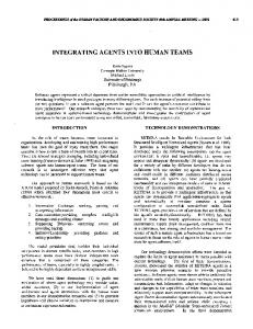
Power System Evolution Traditional Distribution System Structure In the traditional power system, the load in the distribution system is supplied exclusively by power delivered through the substation.1 See Figure 1. In such a system power flow is unidirectional, frequency does not fluctuate significantly, and most of the control effort in the distribution system is focused on maintaining the desired local voltage profile. At the industry level, one function of the traditional power system is to build and operate the power generating capacity that is required to meet the energy and power demands of customers. The traditional industry structure is that of a vertically integrated, regulated industry, operated without the price-based incentives of a competitive market to guide customers and producers in maximizing system efficiency.
1
Occasionally a larger customer may self-generate or cogenerate a portion of their own load.
CONTENTS
9
High Voltage Power Grid Distribution System
Central Generating Facility
Figure 1: The Historical Structure of the Distribution System
Initial Phases of Restructuring
The restructuring process is introducing market forces to the power industry in general, and to the generation sector in particular. In the first stages of restructuring a few small scale generators may be installed in distribution systems. Initially though, restructuring efforts in the distribution system are likely to focus on capturing the price elasticity or price responsiveness of customers, since efforts in this area will not be as complex or time consuming as building new power plants. As more customers are charged based on the actual cost of supply, variations in local frequency and voltage may exceed the ranges common in the current system. These variations will be selfcorrecting to some extent due to the response of frequency sensitive load and local VAR support equipment. The point of interest is that it is possible that the variations in local frequency and voltage may exceed those typical in the traditional distribution system, even before any small scale generation is installed in the system (simply as a result of customers responding to market incentives). If this does occur, it will be the first indication of a need to establish market driven methods for ensuring the desired level of power quality and reliability in the distribution system. In such a system it will be customers, via market forces, who determine the allowable deviations of frequency and voltage from the nominal values.
10
CONTENTS
Bulk Power Grid
Figure 2: The Future Structure of the Distribution System with Multiple Distributed Generators The Future Distribution System with Increased Penetration of Distributed Generation One focus of this report is analyzing the performance of the distribution system in response to an increased penetration of distributed generation. Further into the future of the restructuring process it is likely that multiple distributed generators will be sited in each distribution system as shown in Figure 2, which shows customers and different types of generators distributed throughout the system. Reasons for interest in these generators were discussed earlier in this chapter. It is this anticipated direction of power system evolution—one which assumes a significant role for distributed generation—which raises the questions addressed in this report. One set of questions focuses on the behavior of small scale generators within a single distribution system and the performance of the distribution system itself. The industry restructuring process raises engineering concerns of maintaining system performance levels (local frequency and voltage in particular), as a growing number of active devices with diverse characteristics are sited within the distribution system. The fundamental changes to distribution system behavior introduced by distributed generation may demand that the issue of local (geographical) stability be revisited. Strengthening the technical capability for decentralized control and dispatch of generation, to parallel the growing potential for independent ownership will also be of interest in the restructured
CONTENTS
11
industry. Assuming that it does not compromise stability, decentralized control is desirable because it will facilitate non-utility ownership by allowing non-utility generators to be more fully independent from the local utility or other centralized system coordination authority. A second focus of this report is the development of a closed loop price model to coordinate the actions of distributed generators as they participate in the emerging competitive market. This price signal is designed to maintain the desired system performance and guide distributed generators as they participate in both the short run energy market and the ancillary services2 market. Legitimate concerns are raised over the extent to which market forces can replace the traditional centralized command and control structure. Will a system controlled in a decentralized manner consistently have access to the resources required to meet system demand and respond to system fluctuations? When should criteria other than market efficiency take precedence in operating decisions? Can a price signal be used to coordinate energy transactions? Can this price signal be used for system regulation3 as well as for bulk energy exchange? The price signal proposed in this report facilitates the desired industry transition toward increased independent and decentralized generator decision making, by conveying efficiency incentives to generators through market mechanisms, without compromising system performance. The closed loop price signal is consistent with the industry restructuring goals in that it frees the system operator from the extensive information requirements of the centrally controlled systems common today. With the closed loop price signal proposed here, the system operator does not require access to cost or technical performance characteristics of the individual and independent units. Instead, this information remains private, and generators make independent operating decisions in response to the close loop price signal. The simulations with the price model demonstrate that this type of signal can be used to coordinate energy transactions and meet system regulation needs.
The Future Distributed Utility The power system will eventually evolve into what can be referred to as a distributed utility, as shown in Figure 3. Distributed generators are one component of the distributed utility concept—a concept that anticipates an increased use of distributed resources in order to increase the efficiency of the power system. A fully distributed utility architecture is one where no incentives can be found, 2
As defined by the FERC, ancillary services are compensation for losses, load frequency control, automatic generation control, voltage support, spinning reserves, scheduling and unit commitment, and monitoring and control. 3 Regulation refers to the engineering control functions, and not the economic idea of industry regulation.
12
CONTENTS
whether to add a technology or implement an additional operating strategy, which will improve the system performance [60].4 New generating and control technologies will continually improve system efficiency, but at any given point in time there is a maximum achievable efficiency. The distributed utility architecture is not unique, but instead is defined for a specific system at a given point in time, as a function of the current system architecture and the existing technologies. Once the behavior of distributed generation, operating in a competitive market, and within a single distribution system is understood, this report examines the performance of a future distributed utility, using the closed loop price signal to coordinate generator actions. To model the operation of a future distributed utility, this report assumes that distributed resources are located throughout the system, and are free to contract to supply load anywhere in the system—they are not restricted to operate within their local distribution system. In this phase of the restructuring process the closed loop price signal as developed in this report is particularly important. The price signal is effective in guiding generator operations in a setting where the generator operating decisions are based on private economic incentives, and are not controlled by a central authority. To understand the significance of the price framework developed in this report, it is useful to consider the following example. Suppose that the small generator in System B of Figure 3 decides to supply a customer in the lower left, because the market price in System C is greater than that in System B. If the total generation in system B exceeds that system’s demand, then there will be a power mismatch within the distribution system, which may have negative impacts on the system performance—the local frequency in this case (see Section and Chapter B). In the power system today, there are sophisticated control strategies to counteract such supply-demand mismatches at the transmission level. The example presented for Figure 3 differs from the situation common in today’s system for two reasons: 1. The existing hierarchical control strategies have been developed predominantly for the transmission system. Since there is little or no generation in the traditional distribution system, no parallel control strategies have been developed for that system, and 2. The example is set in the restructured, competitive market driven power system, not the traditional centrally controlled and regulated system. 4
Efficiency refers to both technological and economic efficiency.
CONTENTS
13
System A
ρmkt
High Voltage Power Grid
ρmkt
System B
ρmkt
System C
Figure 3: Distributed Generation in a Future Distributed Utility
14
CONTENTS
The question then is: What form of control structure will be developed for the future power system, such that bilateral transactions between any two distributed resources will not have negative impacts on power system performance (frequency behavior in this example)? The closed loop price signal developed in this report presents one method to maintain the desired system performance. In response to the excess generation in System B, the market price for ancillary services in that system would increase, or more specifically the price offered for services of the form of frequency stabilization, or designating some currently utilized capacity to spinning reserve, would increase. This price increase would trigger a decrease in power generation, until the price in System B rose to match that in System C. In this manner, equilibrium would be restored via the price signal—i.e. the market mechanism. Note that the closed loop price signal is certainly not the only means to control the system in response to the hypothesized power mismatch. It does however, have the advantage of being consistent with the emerging competitive market structure, in contrast to traditional control strategies which are centralized and tend to rely on access to what will become private information.
Power System Dynamic Behavior This report continues from the earlier research project at MIT on the Distributed Utility System Architecture [60], and focuses on a fundamental research issue raised in the summary of that report—the development of models for control and pricing structures required for the analysis and operation of an efficient, distributed electric power system. Distributed generation and storage units are considered by many in the power industry to be alternative and unproven technologies. Research for this report addresses some issues around their technical integration into and dynamic interactions with the existing distribution system, and one potential method for their operation within a competitive environment. Distributed generation (which for the purposes of this project refers to small generators (500kW to 25MW) located in the distribution system of a traditional electric power utility) are modeled and analyzed. The research for this report focuses on developing dynamic, state space models which incorporate a closed-loop, price based control signal, and uses these models to analyze the dynamic behavior of a distribution system with distributed generation operating within a hierarchical control structure. This report analyzes the distribution system and generator dynamics that are driven by deviations from the scheduled demand (and equivalent scheduled generation), as shown in the sequence
CONTENTS
15
2.5
Total Demand
Normalized Demand
2
1.5
Commercial AC
1
Residential AC
0.5
0 0
Street Lighting 5
10
15
20
25
Hours
Figure 4: Scheduled Demand
of figures, from Figure 4 to 8. Figure 4 shows the demand in a hypothetical distribution system for one day, from three sources. Figure 5 shows the output from three generators, along with the total generation, as scheduled to meet this demand. Figure 6 next graphs the (exaggerated) result of deviations in both the supply and demand from the schedule. The total hourly mismatch between the supply and demand is shown as the bottom line in this figure. The analysis in this report is based on power deviations which follow the same pattern, but are focused on a shorter time scale. Figure 7 mirrors Figure 6, for a period of one hour, plotting only the scheduled power flow and the mismatch. Note that in this figure, it is now assumed that disturbances will only occur at five minute intervals, and that between these steps, power flow is constant. This same data is graphed in Figure 8 which now plots the “mismatch” explicitly as a deviation from the scheduled power flows. With respect to the investigation of distribution system and generator dynamics, this report first analyzes the dynamic behavior at the level of primary dynamics, following a system disturbance as shown in Figure 8. After methods are established to ensure stability at the primary dynamics level, this report investigates the behavior of a distributed utility system at the secondary and tertiary dynamics levels. The closed loop price signal developed in this report operates at the secondary and tertiary levels.
16
CONTENTS
2.5
Total Generation
Normalized Supply
2
1.5
Generator 3 1
Generator 2
0.5
Generator 1 0 0
5
10
15
20
25
Hour
Figure 5: Scheduled Generation
3
Normalized Generation / Demand
2.5
Actual Demand
2
1.5 Actual Generation 1
Supply−Demand Mismatch
0.5
0
−0.5 0
5
10
15
20
25
Hour
Figure 6: Mismatch Between Scheduled Generation and Scheduled Demand
CONTENTS
17
2.5
2
Schedule
Normalized Power
1.5
1
Mismatch
0.5
0
−0.5 0
10
20
30 Time (minutes)
40
50
60
Figure 7: Mismatch Between Scheduled Generation and Scheduled Demand During One Hour
2.5
Normalized Power
2
Schedule 1.5
Deviations from Schedule 1
0.5
0 0
10
20
30 Time (minutes)
40
50
60
Figure 8: Mismatch Represented as Deviations from the Schedule
18
CONTENTS
Conclusions and Recommendations The main conclusions from the analysis at the primary dynamics level, focusing first on frequency behavior, are: • Local frequency in the distribution system can become unstable depending on the type and number of distributed generators in the the system. Altering the location of the generators does not affect the stability of the system. These results were demonstrated with models and system simulations. • One method that was developed for ensuring frequency stability involves developing specific standards, or ranges, for governor setting on distributed generators. This proposed method to ensure local frequency stability is easily implemented, though it does represent a change from existing practice. Currently on the transmission system, generator governors on the large, central generating facilities react more slowly than those on small distributed generators, and so are not relied upon for maintaining system stability. The analysis in this report demonstrated that local generator governors can be used at the distribution level to ensure frequency stability. Continuing to focus on the engineering integration of distributed generators, general conclusions from the discussion with respect to voltage support in the distribution system are: • Generators operated as synchronous condensors can provide local voltage support, • Power conditioning and power electronic equipment increase the flexibility of distributed generators, allowing them to be used in the same manner as static VAR compensators and FACTS devices are, to provide local voltage support, • Both of these possibilities have the potential to increase the value of DG units to the system, but unless this capability is recognized and compensated (financially), it is unlikely that distributed generators will provide this service, forcing the ISO to purchase local voltage support from other suppliers. This first part of the report discussed many issues related to an increased penetration of distributed generation in the distribution system. Factors involved with siting and mode of operation decisions were addressed in general terms. Detailed modeling and simulations were performed for decoupled real power – frequency dynamics.
CONTENTS
19
The second part of the report addresses the market integration of distributed generation. It focuses primarily on secondary level dynamics and the development and analysis of a model for a closed loop price signal, used to coordinate the actions of distributed generators in a future competitive market. It is assumed that the owners of the new, small generators would to operate in the emerging competitive markets, independent of a central authority. These distributed generators would further require an incentive to supply ancillary services, or they would be likely to concentrate on the supply and demand market for real power. The main conclusions from this part of the report are: • A closed loop price signal, as designed in this report, will allow distributed generators to operate in a competitive market without depending upon the extensive information and centralized control structure of the traditional power system, • The closed loop price signal was shown to function successfully in an ideal competitive market as well as other scenarios, such as: 1. Not every distributed generator may choose to participate in the price framework. In this situation those generators not participating are likely to produce at a cost above the system marginal cost, reflecting a suboptimal level of efficiency and performance at the system level. 2. If there is a mix of non-dispatchable (NDT) and dispatchable generation technologies in the distribution system, the dispatchable technologies may be forced to provide system balancing and ancillary services to compensate for the stochastic changes in NDT output, much as they compensate for the stochastic deviations in demand. 3. When the generators operate with imperfect information—information critical to determining private operating decisions—the system converges to the price equilibrium more slowly than when perfect information is available, • To maintain the desired power system performance, the future system may need to develop a coordinated transmission-distribution performance standard. This report demonstrates that if generators are to be sited in the distribution system in significant numbers, then operations and control issues that have historically been of concern only at the transmission level may become concerns for the distribution level as well. The final item above simply points out that if this does happen, then standards and operating procedures may need to be
20
CONTENTS
developed in a coordinated fashion for the transmission and distribution systems. In summary, this part of the report demonstrates that a closed loop price signal can be used to coordinate generator actions in a competitive market while also maintaining the desired level of system reliability and stability.
Additional findings from this research are • The development of a set of state space models for a variety of distributed generation technologies, • The generalization of the secondary dynamics modeling methodology, • The development of a generator cost equation which reflects the marginal cost of all equipment and processes involved in the operation of distributed generators. The increased accuracy in the cost equation (i.e. basing cost on more than simply fuel cost or heat rate curves) is important for operation in a competitive market, • The development of a closed loop price signal that is consistent with both economic principles and the existing power system control framework, • The development of a hierarchical market structure to parallel the existing hierarchical engineering control structure at the transmission level. The market driven control signal developed in this report is an important element of the industry restructuring process because it will promote: • The development of competitive markets, • The full integration of distributed generators into these markets, and • The opportunities for distributed generators to provide both real power and ancillary services.
Operation and Control of Distributed Generation Contributors: Cardell, Ili´c, Tabors
0.1
Introduction
The growing interest in small, distributed generators represent one component of the broader theoretical concept of a distributed utility. This concept focuses on the evolution of the power system as it responds to technological advances, industry restructuring and the uncertainties associated with these changes. As a result of the relative newness of the idea and the variety of related projects, the term distributed utility has already come to be used differently by various practitioners. For example, the emphasis can be on demand side management, generation, storage, automation or any combination of these. Generators of interest might be new, alternative technologies such as fuel cells and storage facilities, or fossil fuel technologies (of relatively smaller capacity), such as gas turbines and cogeneration facilities, or renewable energy technologies or any combination of these. The plant capacity of interest can range from tens of kilowatts to 25 MW or more. And finally the siting options can include the sub-transmission system, urban or suburban distribution systems, or more remote rural locations. These differences aside, the commonalities in the usage of the terms distributed generation or distributed utility lie in the assumption of increased interest in alternative small-scale technologies which are installed in closer proximity to the load than is current practice. For the purposes of this report the term distributed generation refers to small generators (500kW to 1MW) located in the distribution system (i.e. the radial component) of a traditional electric power utility.
22
CONTENTS This report discusses both engineering and economic market coordination issues associated with
what some consider to be unproven technologies. It is important to recognize that any discussion of the long term benefits of distributed generation-financial and economic-necessarily assumes that the power system will continue to be stable and reliable. Will numerous distributed generators adversely impact system stability? Will voltage and frequency remain within specified bounds of their nominal values? Will all load will be met with specified (high) probability? To address these concerns, the first section of this report demonstrates that there are some situations where this assumption of continued stable operation may be unfounded. This fact suggests that close attention should be paid to the technical characteristics of distributed generators if large numbers are to be successfully incorporated into the power system. The report next describes a possible structure for a competitive energy and ancillary services market with many independent players. The final section in the report demonstrates the role of price in coordinating the operation of distributed generators in the distribution system of a restructured power system. The role of prices in coordinating both the technical and economic operations of a power system with distributed generation, as described in this report, is demonstrated through the use of simulations with a sample distribution system operating in a competitive market for energy. Using the model, with the introduction of a price feedback signal from the market coordinator or the ISO, we show how distributed generators may be coordinated such that the system will not always require centralized control to maintain reliability and stability.
0.2
Technical Issues for Distributed Generation
Much of the attention distributed generators receive is focused on the long term benefits they offer in terms of their economic and financial characteristics and potential for promoting efficient system expansion (whether a central utility or independent project). Engineering issues associated with distributed generators are tied to phenomena which evolve over a much shorter time frame, such as frequency and voltage stability, automatic generation control (AGC), spinning reserve, load following, and other ancillary services. It is not the objective of this section to focus on ancillary services for a future restructured industry—a discussion of greater relevance to the high voltage transmission system than to the distribution system. Nonetheless, with the potential of siting small scale generators in the distribution system, a subset of these concerns—specifically the issues of stability and reliability within the local systems—merits examination. Only after system stability
0.2. Technical Issues for Distributed Generation
23
over the short time frame is assured can the discussion move to longer time frames and a discussion of the economic operation of a radial system with distributed generation. To explore the stability concerns, a model with examples of several distributed generators operating within the distribution system is developed. This model is used to demonstrate that it is possible, in some operating situations, for the distribution system to go unstable. It is important to note that these situations are unexpected since similar generator configurations on the high voltage grid would not result in stability problems. Several approaches for ensuring system stability in these situations are discussed at the end of this section.
0.2.1
Distribution System Characteristics
It is important to identify the differences between the distribution and the high voltage transmission systems in order to understand why the means for maintaining stability differ. Most existing distribution systems were designed to passively distribute energy generated on the high voltage grid to consumers connected to the local system. Therefore, one feature of the distribution system is that typically it contains only consumers, or load buses, and not power generators or other active supply sources. In such a system, power flows in one direction only—from the substation to consumers. A second related difference arises from the physical structure of the system. The traditional power distribution system is radial, or looped, in contrast to the highly meshed network of the high voltage transmission grid. For a distribution system then, there is one, or at most two, paths to each bus, as opposed to multiple paths to each bus in the transmission grid. A third important distinction lies in the electrical properties of the power lines themselves. High voltage lines have relatively low resistance while low voltage lines in the distribution system have a larger relative resistance. These differences affect the strength and number of interconnections between generators and load buses, and therefore the degree to which the interconnected generators can affect one another and the connected loads. The final distinction between the distribution and transmission systems is the extent and type of control framework historically required to maintain system stability and desired operation. Supervisory Control and Data Acquisition (SCADA) systems and Automatic Generation Control (AGC) are two well known and long standing control frameworks commonly part of power system control and operation strategies, which typically are implemented exclusively at the high voltage transmission level. Limited automatic control and data gathering are being gradually introduced into the distribution system, however such automation is not yet common at the distribution level
24
CONTENTS
in the United States. The modeling in this report demonstrates that any meaningful presence of distributed generation will require a concurrent increase in the extent and sophistication of both the control framework and data acquisition systems. As we show, until such control is implemented, there could be unexpected and undesirable consequences of installing multiple distributed generators in existing distribution systems.
0.2.2
Developing a Dynamic System Model
The established engineering methods for maintaining stable system operation have been designed to meet the requirements of generators that are traditionally located at the transmission level. The discussion which follows focuses on frequency stability in the distribution system, and analyzes whether the integration of multiple distributed generators into a radial distribution system can adversely affect system stability. If large numbers of distributed generators do affect system performance, then it is important to explore modifications that may be required to the existing generator operations or control strategies in order to maintain system stability. To explore the system dynamics of interest, a model is developed below and then used for simulating dynamic interactions of distributed generators in a distribution system. The first step in developing the model is to identify the variables of interest. For the purposes of the analysis of frequency stability, the primary values of interest at each bus, i, are frequency, ωGi , and real power output, PGi . Frequency stability is analyzed by tracking the frequency at each bus as it evolves over time. If the frequency values either remain constant (at the nominal 60 Hz value) or converge to a different equilibrium value, then the system frequency is stable. On the other hand, if a small disturbance at one bus in the system, such as an increase or decrease in demand, causes the frequency at one or more other buses to diverge from an equilibrium, then the system is defined as being unstable. On an actual system such an event represents loss of synchronism. Mathematically, the dynamics of the system are represented through a series of linear, differential equations, expressing the time evolution of the system values of interest. These system values are referred to as state variables since they capture everything of interest about the current state of the system. For each state variable, the model contains one equation that represents the relationship between that variable and all other variables in the system. A simple model for a combustion turbine-generator, which includes both ωGi , and PGi as identified above, is developed below. In the first step, ωG is identified as the state variable for the generator, VCE is the variable for the fuel controller, and WF and WF d are both necessary to
0.2. Technical Issues for Distributed Generation
25
represent the fuel flow. The set of combustion turbine-generator equations is: M ω˙ G = −DωG + cWF − PG bV˙ CE ˙F W
= −KD ωG − VCE + KD ω ref = WF d
(1)
˙ F d = aVCE − δWF − βWF d αW In these equations M is the inertia constant, D is the damping coefficient and the ’. ’ signifies time rate of change, dx/dt. The remaining parameters are the coefficients for the linear relationship between the state variables specified. They are defined in references (Calovic 1971, IEEE 1973, IEEE 1991). To build the complete system model, the individual generator models are coupled to each other via the distribution system. To achieve this coupling each set of equations representing a local generator is expanded to include the system coupling variable, selected to be power output or PGi . Beginning with the linearized load flow equations, the following differential equation for real power can be derived (Liu 1994). P˙G = KP ωG + DP P˙L
(2)
In this equation represents a load disturbance (or the change in load with respect to time, which requires the ’. ’ notation) and is the input variable to the system of equations. The matrices K and L are derived from the Jacobian matrix for the distribution system. Expressed in standard format the full system of equations for the model is written as: M ω˙ G = −DωG + cWF − PG bV˙ CE ˙F W
= −KD ωG − VCE + KD ω ref = WF d
(3)
˙ F d = aVCE − δWF − βWF d αW P˙G = KP ωG + DP P˙L or more compactly as x˙ = Ax + BP˙L
(4)
where x represents the vector of state variables related to the system dynamics (specifically ωG ,
26
CONTENTS
21
1 Bulk Power Grid
2
19
20
6
7
8
5
9
4
10
17 15
16
11
12
22
28 29
3
18
30
23
13 14
24
25
26
27
Figure 9: 30 Bus Radial Distribution Test System VCE , WF , WF d and PG for this example), and A and B are constant, non-zero matrices of the parameters expressing the linear relationship between these variables. If all load values remain constant then the input vector P˙ L is identically zero. Whenever a load increases or decreases, a disturbance results, which in the model is expressed as a non-zero value for P˙L . For the nondispatchable technologies such as wind and photovoltaics a fluctuation in the wind or solar resource represents a system disturbance. The model in this form is used for the simulations below.
0.2.3
Sample Distributed Generation Systems
The distribution network used for the examples in this report is shown in Figure 1, the data for which can be found in (Grainger 1985, Santoso 1989). Only the buses with generators and the load disturbance are labeled. All other buses, 25 of the 31, are static load buses. (Note that the total load is dispersed throughout the system, with every unlabeled node representing a static load bus.) Total load on the system is 14 MW and the total capacity from distributed generation varies from 1.4 MW to 2.5 MW in the examples presented. To explore whether multiple distributed generators could adversely impact system stability we use the model described above to simulate the dynamics of a distribution system under different scenarios which vary the distribution of load and the location, types and numbers of distributed generators connected to the system.
0.2. Technical Issues for Distributed Generation
27
−5
4
x 10
Steam
Frequency Deviation (Hz)
2
0
−2
−4
−6 CT −8
−10 0
2
4
6
8 10 Time (seconds)
12
14
16
Figure 10: Base Case—Frequency Deviation After Load Deviation Turbine The first example has a 700 kW steam turbine at generator 1, and a 700 kW combustion turbine at generator 2 (as well as a slack bus5 at the substation). The load disturbance is a small increase in demand at time equals 2 seconds. Figure 2 shows the frequency deviation from the equilibrium point at all generator buses for this system. (The unlabeled line in the figure represents the frequency at the substation, or slack bus.) The system is stable so long as the frequency deviation over time converges to an equilibrium value. The rotor frequency for the small turbines is seen to oscillate around the nominal 60Hz frequency, and then converge to a slightly slower value. The behavior demonstrated by the system in Figure 2 is the desired behavior. The system is next modeled with four combustion turbines, ranging from 500 kW to 750 kW, (with a total of 2.5 MW) distributed throughout the system, as identified in Figure 1. The turbines have slightly different values for the controller gains (KD in Equation (1)), all within the ranges as specified in (Hannett and Khan 1993, Hannett, Jee and Fardanesh 1995, Rowen 1983). The frequency behavior of two of these generators, along with the slack bus, is plotted in Figure 3. (The frequency deviations of the remaining generators are not plotted to avoid confusion in the 5
A slack bus is an artifact of the need to maintain power flow balance on the system. Load flow analyses include one bus where the real power remains unspecified, a bus designated to take up the ’slack’ and balance the power flow on the system. This bus is referred to as the slack bus, which in this report is used to represent the bulk power system. This is conceptually consistent since the bulk power system is assumed to supply any power necessary to maintain the power balance within the distribution system.
28
CONTENTS
−5
4
x 10
Frequency Deviation(Hz)
3
CT
2 CT 1 0 −1 −2 −3 −4 −5 0
2
4
6
8 10 Time (seconds)
12
14
16
Figure 11: Frequency Deviation for System with Four Combustion Turbines
figure.) This figure clearly demonstrates that local system frequency in this example becomes unstable given the same load disturbance as in the first example. It is significant to note that the system remains stable when only two combustion turbines are in the system. It is not until there are four generators that the instability is seen, suggesting that at least for frequency stability technical problems may arise only as the number of distributed generators increases. In the third example, when a single hydroelectric generator is modeled as generator 1 the frequency also becomes unstable. With a combustion turbine added to the system at generator 2 (both generators of capacity 750 kW), the instability caused by the hydroelectric plant creates instability at the combustion turbine bus as well. See Figure 4. The instability found in the above example can be avoided by carefully tuning the generator to the specific system. Note that the hydro plant as modeled has all parameters set within the ranges as established for existing small hydro facilities. The point of this example is not that hydro or any other small scale generating technology will automatically cause frequency instability, but rather that it is possible for them to do so unless close attention is paid to the new situation represented by siting multiple generators in a radial distribution system. Note also that the instability remains local to the distribution system in all examples; the slack bus frequency never diverges from an equilibrium value, as is consistent with modeling the bulk power system as a slack bus.
0.2. Technical Issues for Distributed Generation
29
−4
4
x 10
Frequency Deviation (Hz)
3 2
Hydro
1 CT 0 −1 −2 −3 −4 −5 0
2
4
6
8 10 Time (seconds)
12
14
16
Figure 12: Frequency Deviation with Hydroelectric and Combustion Turbines
0.2.4
Sources of System Instability
The cause of the frequency instability in the distributed generation systems is discussed next. Two properties of the distributed generation systems are seen to impact the nature of the system dynamics, such that the distribution system may respond differently to disturbances than does the transmission grid. First, in evaluation of the high voltage transmission system it is correctly assumed that the local generator dynamics—i.e. variations in frequency—are slow relative to the dynamics of the transmission network itself. The implication of this assumption is that a change in a local state variable (frequency) at any bus is instantaneously transmitted through the system, without any noticeable affect of the network itself on the disturbance or the local generator dynamics. As described above the distribution system has relatively high impedance and a radial structure, which translates to weaker interconnections between all buses. The significance of this can be better understood by drawing an analogy to a mechanical spring and mass system where the spring represents a power line and the mass a generator rotor. In the mechanical system if the mass is displaced, it is restored to its equilibrium position more or less quickly depending on the strength of the spring. In a power system, a frequency change implies a change in the relative positions of the generator rotors. The rotors will be restored to their synchronous positions more or less
30
CONTENTS
quickly depending on the strength of the interconnection (where a large impedance represents a weak interconnection). A second distinction is that the generators on the high voltage grid are very large with correspondingly large mechanical inertias, in comparison to the small distributed generators. The smaller machine inertias compound the network affect on the local frequency by being too small to effectively counteract the oscillations from the disturbance. These observations of large line impedance and small inertias are not surprising. What is unexpected is that they are significant enough to potentially affect stability within the distribution system.
0.2.5
Methods for Stabilizing the System
For the examples discussed in this report the local dynamics of all generators independently and the network itself are stable (which can be verified by performing an eigenvalue analysis). Nonetheless, some system configurations, such as those presented above, may exhibit instability. This result has practical application in defining a process to stabilize the system. Currently, for the high voltage transmission network it is assumed that system stability can be ensured if each generator is stabilized individually against the system (represented as an infinite or slack bus) and then connected to the network. The instability found with the examples in this report suggest that the methodology necessary for initially stabilizing a distributed generation system could differ from this current practice. The stability problem suggests that local control design and/or ranges for generator settings may call for renewed attention to ensure that stability will be maintained in a radial distribution system with numerous distributed generators. A general method for specifying ranges for the values of local parameters (the linearized coefficients on the right hand side of the Equations (1) and (3)) is to calculate eigenvalue sensitivity to these parameters, for the unstable system eigenvalues. The sensitivity matrix, Si , for the ith eigenvalue is defined to be Si = [∂λi /∂ajk ] = wi vi�
(5)
where the λi are the eigenvalues of the system, the ajk are the local control parameters, and wi and vi are the left and right eigenvectors respectively for the ith eigenvalue (where vi is a row vector). This matrix is calculated for the unstable eigenvalues for each system with instability, examples of which are shown in Figures 3 and 4. The sensitivity matrix shows that for the systems with a
0.2. Technical Issues for Distributed Generation
31
−4
1
x 10
Frequency Deviation(Hz)
0.5
0
−0.5 CT −1
−1.5 Hydro −2
−2.5 0
2
4
6
8 10 Time (seconds)
12
14
16
Figure 13: Hydro Gate Opening Time Constant Increased
hydroelectric plant, the unstable behavior (or the unstable mode) is most sensitive to the parameter representing the time constant for the gate position or opening, suggesting that this time constant would be a good value to adjust. Figure 5 shows the system of Figure 4, with the time constant for the gate opening of the hydro plant increased so that it can not react as quickly to a disturbance, preventing it from resonating with the oscillations. (The unlabeled, dotted line on this and the following figure represents the substation or slack bus.) Note that although this solution solves the stability problem, it also serves to challenge one of the anticipated benefits of distributed generation, specifically that the fast response capabilities of small generators would be beneficial in responding quickly to changes in demand and so help minimize any disturbance. A second parameter found to significantly affect the stability is the inertia constant, M , which implies a potential stability benefit from specifying a minimum inertia, or size of plant installed. For the system with only combustion turbines (Figure 3), the greatest sensitivity is found in the gain of the fuel system controller. (See (Rowen 1983) for detailed explanation of these parameters.) When this gain is decreased, the system is stabilized. Note that the system modeled for Figure 4 has both a hydro generator and a combustion turbine, and that the gain in the CT fuel system controller is not identified as a parameter to which the instability is significantly sensitive for this system configuration-a finding which demonstrates that the instability is a system phenomenon,
32
CONTENTS
and not caused by only one generator or generator type.
0.2.6
Summary
The first part of this report has described the modeling approach used to simulate the frequency dynamics for a distribution system with small, distributed generators. Instability was found, and examining the sensitivity matrix suggested various methods for stabilizing the system, requiring that close attention be paid to local control parameters-time constants and gains, or to generator selection-machine size or inertia. It was also demonstrated, that in some cases instability may only occur as the number of distributed generators in the distribution system increases. The frequency issues raised in the previous section are not new to power systems, but are new to the distribution system. One difference in the solutions suggested here from those currently implemented on the high voltage grid is the focus on using the local generator controls, including governors, to secure frequency stability. At the high voltage level, local controls such as governors react more slowly and so are not relied upon for maintaining system stability. In contrast, the analysis in this section has shown that local generator governors can be used at the distribution level to ensure frequency stability. A drawback of this sensitivity to the governor settings is that at the distribution level generators may not be able to turn off their governors and drift with the system frequency as they can at the transmission level. A deregulated capacity market incorporating distributed generators is more consistent with decentralized than with centralized control. However, the methods for stabilizing the system introduced in this section do require some degree of centralized oversight in determining governor standards or in generator selection. It is important to point out that the frequency concerns for the distribution system raised here are easily addressed. It is vital that the extra stability analysis is performed though, as the penetration of distributed generators increases, so that the potential frequency problems are successfully avoided.
0.3
System Coordination in a Competitive Market
Given these methods to ensure system stability we turn to a discussion of methods for a competitive energy market to operate with multiple, independent distributed generators. In the industry today independent power producers are paid based on long term contracts with utilities. This process has required the utility and regulators to have extensive information on each generating unit in
0.3. System Coordination in a Competitive Market
33
order to determine the optimal contract price. This operational dynamic is inconsistent with the competitive market model we expect to see in the future. This section first discusses potential market structures for the future electric power industry. This is followed by specific examples of distributed generators responding to a price feedback signal which functions to coordinate distributed generator operation in a competitive market structure.
0.3.1
The Energy and Services Markets
Engineering realities play a critical role in the manner in which the restructured power industry will operate. In a market structure in which participants are responsible for balancing their energy supplies and demands, it is likely that an independent system operator (ISO) will be responsible for securing additional capacity resources (generally under short term contract) that it can call upon if needed to supply the ancillary services or reserves necessary to meet its operational obligations. The resources that it maintains are thus made available as necessary, to support the trading of the products in the commercial market which focuses on the delivery of energy. The market structure envisioned in this report assumes that these services can be supplied competitively, and further that a competitive market will be developed at the distribution level. It is assumed that distributed generators will be allowed not only to enter into contracts at the wholesale and retail levels, and participate in the commercial energy market, but also provide ancillary services to the ISO and local customers on a competitive basis. This transition of the electric supply industry toward greater competition in the generation sector will require a parallel transition in the control and operation of generators from the current centralized structure to a more decentralized and market driven framework. A price signal is a basic economic tool for coordinating a competitive market. One way for distributed generators to operate in the future competitive markets is for their local controls to be designed to respond, in real time, to a price signal. With this potential future model for the energy and services market in mind, the report now focuses on short run operational dynamics and the role of distributed generators in both of these markets.
0.3.2
Objectives of the Closed Loop Price Signal
The price signal introduced below is a closed loop signal (i.e. one that incorporates feedback) rather than an open loop signal, as most price signals in the electric supply industry are today.
34
CONTENTS
One objective in introducing a closed loop price signal to the generation sector is to aid in the creation of the desired competitive market. Market based institutions must be purposefully created as regulatory oversight is decreased in the generation sector, or it is likely that the sector will simply become an unregulated monopoly rather than a competitive market. A price signal expresses to consumers and suppliers the efficient levels of demand and supply. A closed loop price signal will capture the market clearing dynamic of a competitive market in the dynamics of the feedback control, and so incorporate market prices into system control decisions as well as in siting and investment decisions. A second goal of the price signal is to provide a decentralized control mechanism which allows each generator to operate independently while also providing an incentive for the generators in aggregate to produce at the efficient level. The price signal facilitates the creation of a decentralized system in which distributed generators are free to act independently, required neither to give control nor any private information to a centralized authority. The objective of the price model is to demonstrate that a market-based price signal can be used in conjunction with the existing bulk flow market price to successfully control and coordinate a distribution system.
0.3.3
The Role of the Closed Loop Price Signal in the Market
The future power system is likely to have competitive markets for both energy and ancillary services. In the proposed price framework the basic piece of information communicated to the distributed generators from the ISO and the market coordinator (or Power Exchange, PX) is the spot price of energy and/or services. This spot price corresponds to the price of the scheduled power flows as determined by the ISO and PX. In the price framework proposed in this report, the full price communicated to the distributed generators via the substation is assumed to represent both the spot price and a component to account for deviations from the scheduled power flows. The magnitude of the price variable in the model presented below represents this component for the deviation from equilibrium and not the full market or absolute value. The full price of energy in the market can thus be expressed as ρbase ± ∆ρ where ∆ρ is the quantity determined by the price based control loop in this report and ρbase is the spot price of the scheduled, bulk power flows. In the context of current power system operation, ∆ρ would likely be calculated after all flows and power output levels are known, or else forecasted using
0.3. System Coordination in a Competitive Market
35
either expected, future values, or historical values. In contrast to this approach, the price control model derived in this report determines ∆ρ dynamically, via feedback, and without centralized control. The price signal can be operated in a flexible time scale. Every k minutes the market or system price, ρbase , is updated to reflect the current price of power delivered to the distribution system. The time step k could be as long as 30 minutes or 1 hour, and so coincide with the spot market as typically defined in the ongoing industry restructuring debate. To capture system regulation needs, and provide market incentives for small generators to provide ancillary services though, the time step k for ∆ρ must be defined for a shorter time step, such as 5 minutes. A significant aspect of the proposed price control structure is that the mathematical representation and corresponding system response are identical whether it is the real-time energy market or the services market that is being modeled. This mirrors events in the actual power system since inside the 30 minute or 1 hour window of the traditional spot market, a change in the demand for energy is the source of the system demand for ancillary services. At this time scale both the services and short term energy markets are driven by deviations from scheduled power flow, and are differentiated only in the length of the time step k, as well as in the perceived cause of the system disturbance. Price based controls are typically precluded from acting this quickly due to the longer time frame assumed necessary for market interactions. It is not a theoretical constraint however that prevents the price feedback from being implemented in the shorter time step—a price signal is capable of acting in this short time period. It is within this shorter time window that system regulation is an issue, and that controls act to stabilize the system. The price signal model demonstrates that both the short run energy and the services markets can be operated competitively.
0.3.4
Anticipated Generator Response to Price Feedback
The closed loop price signal corresponds to the marginal revenue earned by a participating distributed generator, and as dictated by economic theory the competitive suppliers will produce at the level where their marginal cost equals marginal revenue. The price model incorporates this economic objective (M C = M R) into the short run operating strategies of the individual distributed generators such that the generators respond automatically to changes in the system price by altering their output until their marginal costs of production equal the spot price. Figures 7 through 9 demonstrate the anticipated generator response to the price signal. Figure 7 shows a system disturbance on the test system of Figure 1, occurring at time t = 8 minutes, and
36
CONTENTS
System Disturbance
Generator Real Power Outputs 0.05 Power Deviation (pu)
Demand Deviation (pu)
0.1 0.08 0.06 0.04 0.02 0 0
5
10 15 Time (minutes)
CT 0.04
System
0.02 0.01 0 0
20
Steam
0.03
5
10 15 Time (minutes)
20
Figure 14: Load Disturbance with Corresponding Increase in Power Output (No Price Feedback)
Generator Real Power Outputs
Generator Output Price 0.05
CT
CT Price Deviation (pu)
Power Deviation (pu)
0.05 0.04 Steam
0.03
System
0.02 0.01 0 0
5
10 15 Time (minutes)
20
0.04 Steam
0.03
System 0.02 0.01 0 0
5
10 15 Time (minutes)
20
Figure 15: Power Deviation and Corresponding Price Deviation Without Price Feedback
0.3. System Coordination in a Competitive Market
Generator Real Power Outputs
Generator Output Price 0.05
CT
Price Deviation (pu)
Power Deviation (pu)
0.05 0.04 0.03 0.02 0.01 0 0
37
5
10 15 Time (minutes)
20
CT 0.04 0.03 0.02 0.01 0 0
5
10 15 Time (minutes)
20
Figure 16: Power Deviation and Corresponding Price Deviation With Price Feedback the resulting increase in generator output without the price signal implemented. To compare the system response with and without the price signal, Figure 8 first shows this system output and corresponding price deviations without the price feedback implemented. Figure 9 then shows the output and price deviations with the price signal implemented. The price signal, acting at time t = 10 minutes, causes the generators to adjust their output so that the final generation levels are all close to the system price (represented by the lower, dotted line on the graphs). The simulations will be analyzed more fully at the end of this section after the price model has been developed.
0.3.5
Developing The Closed Loop Price Signal Model
In the power system today, there is no closed loop market signal integrated into system operating decisions. Industry restructuring, and particularly the deregulation of generation, is opening the power sector to market forces. As part of this process, price-based market signals will be integrated into the operating decisions at all levels of the power system. An hourly spot market is currently being designed in the regulatory and policy arena, with extensive input from other industry stakeholders. There is at present however, little effort to make this hourly spot market a closed loop structure. Instead the spot market development is following the pattern established in other countries as well as in some areas of this country, by setting the hourly schedule a day in advance, and determining the price as an open loop signal. In addition to the lack of effort in designing a closed loop signal, there is not yet effort to integrate market forces into the operations and control
38
CONTENTS
decisions on a time scale shorter than one hour, such as every five or ten minutes, or even shorter as is consistent with the dynamics of system regulation. This section develops the mathematical framework for a closed loop price signal, designed to coordinate distributed generators as they participate in both the short run energy market and the ancillary services market. A price signal of this form is of interest because it creates the means for competitive market forces to guide operating and control decisions in real-time. Assuming there are no market failures, the efficiency of the power system will improve as the reliance on market forces increases. The development of the closed loop price model begins by expressing the cost of power generation in terms of the state variables in the generator equations. Cost can be incorporated into the state space generator models by writing an output equation to capture the variable costs associated with generating power from any given technology. Referring to the generator model in Equation (3), the cost equation for a combustion turbine would be written as c = cw ωG + cv VCE + cf WF + cW d WF d + cg PG
(6)
The coefficients in this equation represent the marginal cost associated with each piece of equipment or process represented by the specified state variable. In particular, cg is the marginal fuel cost. The significance of the values of the coefficients in the cost equation lies not in the absolute values chosen, but rather in the relative values of the coefficients between the different technologies and distributed generators. It is the relative cost values that capture the real-time differences in using one technology before another. This interpretation of the cost coefficients is valid for all generators modeled except the slack bus. The cost equation for the slack bus is interpreted as representing the cost to the bulk system of generating the power which is supplied to the distribution system. This system cost, and the related price, are represented as ρsys in the discussion below. The generators and the system will respond to the price signal at specific intervals, indicating that the closed loop price signal is best modeled in discrete time. To develop the dynamic form of the equation, the cost equation is added to the set of differential equations for the system (Equation (3)), all time derivatives are set equal to zero, and the equations are solved for cost. Assuming for now that the markets are perfectly competitive, price is assumed to be equal to marginal cost, so
0.3. System Coordination in a Competitive Market
39
that the discrete time cost equation can be expressed in terms of price as xρ [K + 1] = xρ[K] + C1 uρ [K] + C2 (ωG [K + 1] − ωG [K])
(7)
where xρ is the price-based state space, uρ [k] is the control input, (ωG [K + 1] − ωG [K]) is the system input, and the matrices C1 and C2 are algebraic expressions of the cost coefficients. The state space in this model is the vector of differences between each bus price and the market price at the slack bus, such that xρi = ρi − ρsys .6 Given the dynamic equation, the next step is to define the control law. The control signal for updating each generator’s reference frequency, based upon basic feedback control concepts, is proportional to the difference between the marginal cost of power at the given generator and the system or market price. uρ [K] ≡ −Kρ xρ
(8)
uρ [K] ≡ −Kρ (ρi − ρsys )
(9)
or
where uρ is the control signal to the generator’s governor, ρi is the price for real power at generator i at the current production level, and for this analysis is assumed to equal marginal cost, ρs ys is the price the system is willing to pay the distributed generators, and so represents the marginal revenue to these generators, and the constant of proportionality, Kρ , is the controller gain. The basic objective of the feedback control is to drive the system to an equilibrium state where uρ ≡ 0 , implying that (ρi = ρsys ), or M Ci = M Ri for all participating distributed generators. Different methods for determining Kρ have varying data requirements and different implications for the extent that control can be decentralized. A discussion of these tradeoffs is included in Appendix D. Simulations demonstrating the use of the price signal in coordinating distribution system operation and control are presented below.
6 The values here, ρi and ρsys , both represent deviations from equilibrium, as is consistent with the use of linearized models. The variable ρsys is analogous to the δρ value defined earlier as the deviation from the spot price offered by the system. Similarly, ρi can be interpreted as representing the deviation in the bid price at each distribution system bus.
40
CONTENTS
0.3.6
Simulations of Competitive Market Operation
0.3.7
Base Case – Competitive Market
The first example refers back to Figures 8 and 9, as well as to the sample distribution system shown in Figure 1. Recall that the model input is a small load disturbance occurring at time t = 8 minutes. Conceptually the model action is that the market coordinator updates the system price in response to the disturbance, and then the distributed generators respond to this price change by altering their output such that the MC of generation equals the new MR (recall that the MR is defined as the market price since for now all the distributed generators are price takers). Figure 8, without price feedback, shows the generator outputs and purchases from the grid increasing in response to the increase in demand, and the resultant price increase at each generator. Note that the slack bus represents power flow at the substation and so is a proxy for purchases from the grid. The price offered at this bus is ρsys , can be seen to change in response to the disturbance. The two graphs in Figure 9 show the same system operating in a competitive market setting with the price signal implemented. The price signal is updated every ten minutes in this example. The proportion of the increased demand met by each generator is now determined by each the individual economic objective of operating where M C = M R, as well as by system needs to maintain power balance and the nominal system frequency. The lower right graph demonstrates that the relative prices are now much closer than they were without price feedback (upper right graph). These values are not identical though as a result of the competing need to maintain system frequency as well as account for the small system losses.
Non-Participation in Price Feedback The simplest market structure simulated with the price model is the competitive market example above where all the small generators are incorporated into the price control loop. It is likely however, that while the system is in the process of being restructured some generators will elect to not respond to the price signal, instead remaining under direct central control. Figure 10 shows the output and corresponding prices in the test system when there are four combustion turbines installed, but only one has elected to participate in the price feedback framework. The solid line, lowest on the graph represents the system purchases and price, and the line just above the system (dot-dash line) represents the single combustion turbine (CT) that responds to the price signal. The remaining three CTs have elected to not participate in the price feedback system, and as
0.3. System Coordination in a Competitive Market
Generator Output Price
0.025
0.03
0.02
0.025
0.015
Price Deviation (pu)
Power Deviation (pu)
Generator Real Power Outputs
System and Responding CT
0.01 0.005 0 0
5
10 15 Time (minutes)
41
20
0.02 0.015
System and Responding CT
0.01 0.005 0 0
5
10 15 Time (minutes)
20
Figure 17: Generation and Price Deviations with Single CT Participating in Price Feedback a result they do not reduce their output to match ρi to ρsys . An important point to note though is that this does not imply that they are now receiving the higher price corresponding to the level on the right-hand graph. The price they receive is determined exogenously by the central authority, and the right-hand graph shows the price at the generators of producing at the given level, but not the price they receive. The generators not participating are seen to produce at a level above the system marginal cost. This result can be interpreted as reflecting a suboptimal level of system efficiency and performance, due to the non-competitive decision making of three of the generators.
0.3.8
Non-Dispatchable Technologies: Wind Turbines
In addition to the scenario introduced above, this mix of participating and non-participating generators can result when some of the generators are non-dispatchable technologies (NDTs) which do not have primary controllers, such as wind turbines. The stability of the system with such a mix of technologies is simulated next. The first example with NDTs replaces the steam turbine from the previous example with a wind turbine. The wind turbine is a non-dispatchable technology (NDT), and is assumed not to participate in the price feedback framework. The small increase in wind turbine output after the load disturbance at t = 8 minutes is a consequence of the fact that system frequency is briefly disturbed from its nominal value, and so momentarily affects the output from the wind turbine. (The link between rotor frequency, system frequency and power output was mentioned above.) This
42
CONTENTS
Generator Real Power Outputs
Generator Output Price 0.08
0.05
Price Deviation (pu)
Power Deviation (pu)
0.06
0.04 0.03 0.02 0.01
0.06
CT
0.04
System
0.02
Wind
0 0
5
10 15 Time (minutes)
20
0 0
5
10 15 Time (minutes)
20
Figure 18: Generation and Price Deviations With Wind Turbine in System example demonstrates the behavior of the system in general if one of the distributed generators is not participating in the price feedback. In such a situation, whether the generator is a nondispatchable or a dispatchable technology, the output of the non-participating generator will not change in response to a change in the reference price except for a small deviation as the system finds its new equilibrium. The system does remain stable. For the second example, the system is the same as in Figure 11 but now the disturbance is an increase in output from the wind turbine at t = 8 minutes rather than a change in demand.7 Figure 12 shows the changes in power and relative price after this disturbance. Both the output from the combustion turbine and the supply through the substation decrease to balance the increased output from the wind turbine (left hand graph). The system price and price of generation at the CT are both seen to decrease in the right hand graph. The interesting point from this example is the dynamic between the wind turbine and the neighboring combustion turbine. As output from the wind turbine increases, the CT is forced to decrease its output to maintain nominal system frequency, with a concurrent decrease in its revenue stream. System fluctuations driven by NDTs in small penetrations will most likely be indistinguishable form fluctuations caused by load changes. At larger penetrations NDTs may cause system fluctuations large enough to noticeably impact the revenue stream of other generators, which will create a tension between the system’s need for 7
Note that the plot for the price deviation of wind is not on the figure since wind does not participate in the closed loop price framework.
0.3. System Coordination in a Competitive Market
Generator Real Power Outputs
Generator Output Price 0 Price Deviation (pu)
Power Deviation (pu)
0.1 Wind
0.05 0
System
−0.05
CT −0.1 0
43
5
10 15 Time (minutes)
20
−0.01 −0.02 −0.03 −0.04
System
−0.05 −0.06 0
CT 5
10 15 Time (minutes)
20
Figure 19: Generation and Price Deviations After Increase in Wind Turbine Output dispatchable technologies to alter their output and those generators’ financial objectives.
0.3.9
Imperfect Information: Uncertainty
The market organization itself is altered for the final category of market interactions. The first variation to the competitive market is a weakening of the assumption of perfect information. Imperfect information results both from uniform uncertainty in measurements and system values, and also from unequal access to system information. Unequal access can result from generators that were originally owned by a utility simply having greater operating experience than new, independent generators. It could also be the result of generators that contract to a power marketer, having access to more extensive, shared information than single units. In either case, one impact of such uncertainty in information will be that the independent generators will calculate their optimal control gain based on an estimated set of parameters, and will then operate in the actual distribution system. The estimated and actual values are likely to be different. Figure 13 shows the response of the system with one hydro and one CT when their estimated parameter values differ from the actual values by 10% to 25%. Figure 13 shows that the system remains stable even with this uncertainty. However, comparing this figure with Figure 9, when there is no uncertainty, reveals that the convergence of the output levels to the target equilibrium, as driven by the price signal, is much slower when there is uncertainty than when there is none.
44
CONTENTS
Generator Real Power Outputs
Generator Output Price 0.1
0.05
Price Deviation (pu)
Power Deviation (pu)
0.06
0.04 0.03 0.02 0.01 0 0
5
10 15 Time (minutes)
20
Hydro 0.08 CT 0.06 System
0.04 0.02 0 0
5
10 15 Time (minutes)
20
Figure 20: System with 1 Hydro and 1 CT: Uncertainty in Parameter Values
0.4
Conclusions
It is possible that an increased penetration of small scale generators in the distribution system will adversely affect system stability and reliability unless new attention is paid to generator controls and their settings. As we demonstrated in this report, an understanding of both the characteristics introduced by these small generators, and the differences between the distribution and transmission systems leads to an understanding of how system stability can be maintained. Identification of significant system characteristics suggested various methods for stabilizing the system, requiring that close attention be paid to generator selection (size or inertia), operating parameters and local control design (time constants and controller gains). It was also demonstrated, that in some cases instability may only occur as the number of distributed generators in the distribution system increases. A deregulated and competitive energy market incorporating distributed generators is more consistent with decentralized than with centralized operation and control strategies. The methods for stabilizing the system introduced in this report do require some degree of centralized control or oversight in generator selection and operation. The second major topic of this report was the development of a price based control signal used to facilitate the coordination of distributed generators in a decentralized and competitive system. The price framework proposed here is strongly grounded in basic feedback control theory. It is assumed that the owners of the new, small generators will operate in the emerging competitive
0.5. Overview of Appendices
45
Integrating Distributed Generation into the Distribution System
Technical Integration
Generator Siting and Mode of Operation
Short Term Control, Ancillary Services, Frequency Stability and Voltage Support
Market Integration
Investment, Entry and Long Run Contracts
Short Run Interactions with Market Institutions
Figure 21: Integration of Distributed Generation into the Distribution System markets, independent of a central authority. These distributed generators will also required an incentive to supply ancillary services, or they would be likely to concentrate on the supply and demand market for real power. This report demonstrated the use of a closed loop price signal which allows distributed generators to operate in a competitive market without depending upon the extensive information and centralized control structure of the traditional power system. This report has also shown that if generators are to be sited in the distribution system in significant numbers, then operations and control issues that have historically been of concern only at the transmission level may become concerns for the distribution level as well. If this does occur, the standards and operating procedures may need to be developed in a coordinated fashion for the transmission and distribution systems.
0.5
Overview of Appendices
This report explores engineering, economic and policy questions associated with integrating small scale distributed generators into the distribution system, as shown in Figure 21. To accommodate the expanded use of distributed generation in the near term, the first part of this report discusses issues for the distribution system such as selecting optimal locations for the generators, integrating them into the general operations of the system, and maintaining system performance as defined by engineering criteria. It is also likely that the operations and control
46
CONTENTS
procedures and related equipment in the distribution system will need to be adapted in response to the presence of active power sources and resulting bi-directional power flow. Appendix A, Operations and Control Setting for Distributed Technologies, introduces both the distributed generator technologies that will be discussed throughout the report, and the current methods for operation and control in the transmission and distribution systems. Traditionally the distribution system has had very little need for dynamic control, though this pattern has been gradually changing as more and more automation is introduced at the distribution level. Some experience gained from operating the high voltage grid and central generating facilities can be applied to the distribution system and small generators. This chapter includes a discussion of distribution automation, and the potential development of more complex distribution management systems in response to both the industry restructuring, and an increased number of generators in the distribution system. Appendix B, Integration of Distributed Generation into Distribution System Operations and Control, discusses issues associated with connecting a large number of generators into the distribution system. Siting and general operational issues are addressed first. The chapter then focuses on analyzing the impacts of distributed generators on system reliability and stability. This chapter presents models for distributed generators and the complete interconnected distribution system. Results from simulating the interconnected system are presented, along with methods to ensure system stability is maintained.
The second part of this report discusses issues for distributed generation that deal with the ability of small generators to participate in the competitive markets which will be established as generation is deregulated and the industry is restructured. The development of a competitive market for generation creates the opportunity for distributed generators (as with all generators) to participate in energy and related markets as independent producers. Two factors influence the ability of small generators to participate in the emerging markets.
• The first factor is the legal and regulatory structure which may constrain the extent to which small generators are allowed to participate in these markets (entry). In particular, the growth of retail competition, and the designation of distributed generation (DG) as part of the distribution versus the generation sector will both shape the role of DG in the emerging competitive markets.
0.5. Overview of Appendices
47
• A second issue is the day to day, and minute to minute operation of these technologies, and the creation of a competitive market to coordinate such short run operation within the distribution system. This short run coordination can be performed by a market based control signal. Where the regulatory structure discussed above is important to the extent that it defines entry criteria into the market, a market- or price-based control signal is important in that it facilitates operation in the markets. The regulatory changes and debate that is currently defining the new system level institutions are discussed in Appendix C, Industry and Market Setting for Distributed Generation. This chapter presents the background of the restructuring process in the electric power industry. The possibility that distributed generators will eventually interact with the emerging system coordination institutions—the Independent System Operator (ISO) and the Power Exchange (PX) is also explored. Finally, this chapter introduces pricing theory, emphasizing both the general concept of a competitive price coordinating market interactions, and also the specific theory of spot pricing. Appendix D, Integration of Distributed Generation into the Market Structure, discusses the operation of distributed generators in the long run contract markets as well as the short run spot energy and services markets. The industry structure and rules for entry into energy markets are in the process of being defined in the Federal and state policy arenas. Much of what will be settled in that debate (for the transmission system and central generating facilities) can probably be extended to the distribution system and small scale generators, with appropriate changes. The focus of Appendix D is on the creation of a closed loop price signal to coordinate distributed generator operations, since such a signal is required if market forces are to be used to guide generator operations, in addition to investment decisions and wholesale contracts decisions. The goal in developing and simulating the price signal in this chapter is to demonstrate the potential for the operation and control of the distribution system by means of market forces and independent production decisions, rather than by the control room of a vertically integrated utility. Appendix E contains the details of the mathematical development of the models used in this report.
Appendix A
Operations and Control Framework for Distributed Technologies Contributors: Cardell, Ili´c
A.1
Introduction
The power system is designed to serve demand that is dispersed over a large geographic area, to maintain sufficient capacity to meet peak demand with high reliability and stable frequency, and to maintain a stable voltage profile. This appendix introduces the small scale generators that are discussed throughout this report, and then discusses the distribution and transmission systems, which together form the delivery system for the electric power industry. Section A.2 introduces the topic of small scale generator modeling by describing the properties of two general types of technologies that are used for distributed applications—non-dispatchable and small scale dispatchable technologies. This section also discusses the specific technologies, and some of their identifying characteristics. To deliver the energy demanded with high reliability, the transmission and distribution systems have developed sophisticated operations and control procedures. Section A.3 turns the discussion to the T&D system by first addressing some of the physical differences between the transmission and distribution systems. Section A.4 introduces some of the operations and control requirements of the transmission system, emphasizing those concepts that may be useful at the distribution level as the penetration of distributed generation increases. Finally, section A.5 discusses the distribution system including the functions that have been automated to date in many systems, the additional
A.2. Distributed Generator Characteristics
49
functions included in more advanced distribution management systems, and the impacts of small generators on system operation.
A.2
Distributed Generator Characteristics
A.2.1
Existing Uses of Distributed Generation
In response to continuing technological improvements and deregulation of generation, a large variety of small generating technologies are considered viable options for supplying power, whether owned independently or by utilities. Certain applications for distributed generation have persisted over the decades even as the industry in general moved toward increased centralized generation. The most common use of distributed generation (DG) is a diesel generator between 0.5 and 5MVA. These units are owned by businesses and other institutions for backup generation, powering elevators, emergency lighting, fire alarms, etc. Between 100MVA and 400MVA of this type of DG is installed in most major US cities, and is expected to be needed only a few hours each year [118]. Such units in industrializing countries may be expected to run one or more hours each day, to compensate for rolling blackouts commonly scheduled in those countries. Combustion turbines are also common DG units. They tend to be more flexible in the type of fuel used, are larger than diesel units, and are run more for peaking capacity than for backup. Fuel cells, photovoltaics and a variety of storage technologies are also in use, although less commonly, as DG units. Existing applications for distributed generation limit the actual hours of operation due to the high cost and low availability of fuel, the (often) lower fuel efficiency than central facilities, and limits imposed by local air quality regulations. Various studies [89] suggest that approximately 200 hours of operation annually (with a maximum installed capacity of 3MW per feeder) are reasonable limits given the above drawbacks to extended distributed generation use. These limits are based on the assumption that the most prevalent DG technology is the diesel genset, and does not account for the benefits of many of the new and renewable energy technologies, which are clean and in the case of fuel cells have additional fuel flexibility.
A.2.2
Dispatchable Technologies
One way to categorize small power generators is in terms of whether they are dispatchable or nondispatchable. Conventional power generating technologies are dispatchable, meaning that they can be controlled by a central authority and relied upon to generate according to the needs of the power
50
Appendix A. Operations and Control Framework for Distributed Technologies
system. This is in contrast to non-dispatchable technologies which generate not as a function of power system needs, but rather as a function of the intermittent availability of their renewable resource (see Section A.2.3 for more discussion). Gensets The most common distributed generator today is the small engine-generator set typically used as backup emergency power by businesses and institutions. The engines can be fueled either by diesel or natural gas, with either induction or synchronous generators. The hours of operation of these engine-generator sets is usually severely limited by local air quality standards, and siting new units is increasingly difficult due to zoning restrictions. Gas-turbine generator sets are also in use, where the turbine is typically fueled by natural gas, but can alternatively run on distillate, pure methane or land-fill gas [29]. Both of these genset technologies, diesel engine and gas turbine, are commercially available with capacities usually in the range of 500kW to 25MW. Cogeneration Small gensets account for the largest percentage of installed capacity of distributed generators. In terms of grid connected units though, cogeneration is currently the most common DG technology. The standard definition of a cogeneration plant is a facility which generates both thermal and electric energy for independent uses. A more general definition, and one used by utilities, is that cogeneration is any independent, customer owned generator. In terms of this broader definition, cogeneration accounts for 70% of the capacity from Qualifying Facilities.1 [29]. Fuel Cells Fuel cells are modular technologies which generate dc power, and are ideally suited for distributed applications due to their low emissions, low noise level, and fuel diversity. The two main fuel cell technologies are the phosphoric acid fuel cell, PAFC, and the molten carbonate fuel cell, MCFC. The PAFC is more expensive than the carbonate cell yet is more readily available. The carbonate cell is more efficient, more compact, and is expected to become less expensive than the phosphoric cell by early next century. For fuel these technologies require supplies of hydrogen at the anode and oxygen at the cathode. Through an electrochemical reaction combining the hydrogen and oxygen, 1
A qualifying facility, or QF, is defined in the 1978 Public Utilities Regulatory Policy Act (PURPA) as an independently owned generating plant of at most 80MW in capacity.
A.2. Distributed Generator Characteristics
51
fuel cells convert the chemical energy in the hydrogen rich stream of gas to electricity and heat. The hydrogen rich gas can be obtained from natural gas, biogas, or directly from pure hydrogen. When fuel cells operate on methane or any fuel other than pure hydrogen they do have pollutant emissions (such as CO, CO2 and N Ox ) associated with their operation. Since there is no combustion process however, these emissions are much lower than those associated with other fossil fuel technologies. Static power converters are used to interconnect fuel cells to the power system, converting the dc power to ac. This power conditioning equipment can also be used to provide VAR support to the system, by changing the power factor of the generated power as needed to supply reactive power to the local inductive loads. Hydroelectric Power In the United States, hydroelectric plants account for approximately 12% of the total generating capacity. Much of this capacity is from facilities classified as “large,” defined as having at least 1000MW capacity. Small hydro plants are also very common, being actively manufactured and installed in more than 100 countries. There are three general categories for smaller hydro plants, micro-hydro of less than 100kW, mini-hydro of 100 to 1000kW, and small-hydro ranging from 1 to 30MW. Typically plants less than 100kW use an induction generator to generate the electricity, while those of greater than 1MW use a synchronous generator. Plants in the intermediate range can use either, depending on design and cost analysis. Many of these smaller plants do not include a dam, but are instead run of the river. This form of operation makes them not fully dispatchable, since they are more dependent upon the variations of water flow in the river than those facilities with a storage reservoir. The different types of small hydro plants can also be sited in irrigation canals, water supply facilities and wastewater treatment plants.
A.2.3
Non-Dispatchable Technologies
A defining feature of non-dispatchable technologies, NDTs, is the nature of their resource, such as solar or wind energy, which is inherently intermittent. This property means that NDTs generate when their resource is available and not necessarily when energy is demanded by utilities or customers. The fact that NDTs can not be controlled or dispatched by central control rooms has made them less popular with utilities and less understood than other technologies. One important point is that although the resource is intermittent, the technologies themselves are very reliable. And
52
Appendix A. Operations and Control Framework for Distributed Technologies
second, the resource is intermittent yet predictable. With multi-year resource and weather data, the resource can be modeled and predicted with high accuracy [13]. Storage can be installed with NDTs so that taken as a unit, the facility is dispatchable. This is not widely done however, since the addition of storage greatly increases the total plant cost. For dynamic analyses, the stochastic nature of the resource can be treated much as load is treated. In this way, a sudden change in the renewable resource impacts the power system the same as an unpredicted change in load, and can be balanced with the same control actions (e.g. governor action from rotating machinery). The two NDTs included in this report are wind turbines and photovoltaics. The discussions that follow address both the resource and the power equipment, since both aspects are important to the operation of NDTs.
Wind Turbines Every ten days, the earth receives solar energy of an amount equal to the world’s entire fossil fuel reserves, and approximately one percent of this is converted to wind energy. This solar radiation is converted to wind energy as a result of the unequal heating of the equator as compared to the poles, and of the oceans as compared to the continents. A second cause of wind is the motion of the earth. The basic properties of the wind are its speed, direction, and fluctuations in this speed and direction. These properties are affected both by local terrain, in terms of vegetation, buildings, and topography, and by the height of the wind above these features. Increased height results in less influence from these surface features, and also leads to an overall increase in wind speed. Wind turbine systems convert the kinetic energy in the wind first to mechanical energy and then to electrical energy. They use the aerodynamic forces of lift and/or drag to produce a torque on a rotating shaft, which is then coupled to the shaft of an electric generator to produce electric power. The turbines can be categorized broadly by the orientation of their axis: horizontal or vertical; with horizontal axis turbines relying mainly on the lift component of the force to produce the rotation, and vertical axis machines using drag. The basic elements of the system are the turbine and blades, the control systems for rotor speed and direction, the electric generator, the tower structure, and the electronics to connect the system to the power system. Control of the turbine speed is important since this directly impacts the frequency (and thus the quality) of the power generated. When there is low penetration of wind turbines on a strong
A.2. Distributed Generator Characteristics
53
power system, the turbines usually rely on the inertia in the power system itself to keep the turbine speed constant at 60 Hz. With no additional controls though, the load and stresses on the blades and thus on the generator, will increase continually with wind speed, and may become excessive at high wind speeds. The generator used in the wind turbine system is usually an induction machine, and can be connected to the power system either directly or with an inverter. A direct connection is cheaper than including an inverter. Capacitors must still be included in the turbine interconnection however, to balance most of the reactive power drawn by the induction machines. The dominant dynamics from a wind farm are the power fluctuations from the hourly wind variations. The dynamics from the shorter wind dynamics are not an issue when even a small number of wind turbines are jointly supplying the power system, since the wind gusts average out over all the turbines. This is not the case when there are only one or two turbines connected for a distributed application [71]. When an inverter is used as an interface between the power system and the turbine, the turbine is allowed to accelerate with wind gusts, and the inverter acts to slowly increase the power output, which in turn decreases the turbine speed. In terms of dynamic interactions, the inverter decouples the generator and power system dynamics, making the wind turbine(s) appear to be a constant power source, where the constant is slowly changing [71].
Photovoltaics Solar radiation is a main source of electromagnetic energy in our environment, and is the resource used by solar cells to generate electric power. At the top of the earth’s atmosphere the energy in the solar spectrum is essentially constant, although it does vary slightly (± 3%) due to seasonal differences in the earth–sun distance. Once inside the atmosphere, solar radiation is significantly altered by both absorption and scattering of the energy by molecules and particles in the earth’s atmosphere. Differences in altitude, latitude and time of day require the solar energy to travel different distances through the atmosphere, thus affecting the spectrum at the earth’s surface to greater or lesser extent. The spectrum is also altered by weather conditions and air pollution. Cloud formations and air pollution particles tend to scatter the energy, thus decreasing the intensity of the energy which reaches the earth’s surface. The two major components of solar insolation are diffuse and direct. Diffuse (horizontal) radiation reaches the earth’s surface after it has been scattered or reradiated by the atmosphere. Direct (normal) radiation travels directly from the sun to the earth’s surface without
54
Appendix A. Operations and Control Framework for Distributed Technologies
being scattered or absorbed by the atmosphere. Photovoltaics, PVs, convert solar insolation directly into electricity via semiconductor technology. Although there are some concentrator PV systems which utilize only direct radiation, flat-plate PV systems, or simply solar cells, use both direct and diffuse energy. To generate power a PV cell must supply both voltage and current. An electric field created at the junction of the n- and p-type semiconductors used in manufacturing the solar cells supplies the voltage. Current is created once the cells are placed in sunlight, where the absorbed photons create free electrons which form the current through the external circuit. When used in electric power applications, a single PV cell must be incorporated into a larger system. A single solar cell can produce about 1 to 2 watts of power. In order to generate more at useful capacities, many PV cells are joined together into modules, and modules are then grouped into arrays. The arrays also require support structures, often have tracking mechanisms, and finally need power conditioning equipment to convert the dc power from the PV arrays into the ac power required by the power system. On cloudless summer days it would be possible for solar facilities to use the power conditioning equipment to supply VAR support. In other weather conditions though, the stochastic nature of the resource precludes the use of PVs as suppliers of ancillary services.
A.3
The Transmission and Distribution Systems
Having introduced the specific generating technologies, Section A.3 introduces the transmission and distribution systems which interconnect the generators to each other and the rest of the power system.
A.3.1
Physical Differences
The transmission and distribution systems differ in a number of technical and physical parameters. One basic difference is the voltage levels of the power lines. Voltage levels at the transmission and subtransmission levels range from 69kV to 1100kV with common values of 138kV and 345kV. The substation is the interface between the subtransmission lines and primary distribution feeders. Common distribution feeder voltage levels are 13.8kV and 23.9kV, with the standard range being 2.2kV to 34.5kV. Service transformers step the voltage down to the utilization voltage at 120/240V. As voltage decreases, line impedance increases, with a concurrent increase in losses and voltage drop along the lines. Voltage is specified according to both the allowed voltage drop along lines and in
A.3. The Transmission and Distribution Systems
55
the ± deviation from the scheduled value at each bus. On the transmission grid, voltage is limited to deviations of distribution level the allowed range is only ± 0.5%. Maintaining the voltage profile in the distribution system is made more difficult by the increased voltage drop along lines. At the utilization level, single phase power lines are usually limited to a few hundred yards in length to avoid excessive losses and voltage drop. A second fundamental difference between the two systems is the structure of the system, in terms of whether it is a meshed or radial network. Transmission systems are meshed networks, connecting central generating facilities to each other and to substations or load centers. The meshed structure provides multiple electrical paths to each bus leading to high reliability and stability of the system. Distribution systems in contrast are almost always radial systems. Though they are often built as loop or meshed networks, they are operated radially by means of switching devices that are kept normally open. This added flexibility from opening and closing switches increases the reliability of the system in comparison to that of a radial system with a single configuration. However, all such systems remain less reliable than meshed networks. The largest advantage of radial systems lies in the ease of analysis and predictability of the system’s operating behavior. The analysis of system performance is made simple by the facts that the direction of power flow is certain, and the load on any element is easily calculated simply by adding the load represented by the downstream customers. Section A.5 discusses the aspects of radial systems that make them more complex to operate, which is an increasingly important consideration as automation becomes more sophisticated. A third general distinction between transmission and distribution is the number of elements (power lines and associated equipment) at each level. For example, a system that has 50 transmission lines might have 100 substations, 600 distribution feeders, and 40,000 service transformers, each serving 2 to 5 customers. The capacity of each individual piece of equipment is less at lower voltage levels. The total capacity though, the product of average individual capacity times the number of units, increases at lower voltage levels. Continuing with the above example, if the total substation capacity were 4500 MVA, feeder capacity might be 6200 MVA with the total capacity of service transformers approaching 9000 MVA [118]. This pattern of increased total capacity at lower voltage levels is the result of the load profile and the lack of temporal coincidence of local peak demands across the system.
56
Appendix A. Operations and Control Framework for Distributed Technologies
A.3.2
Load Shape and Peak Coincidence
From the perspective of distribution system equipment, individual customers cause needle peaks as appliances and machinery are turned on and off [118]. Aggregation of several customers will smooth the needle peaks to some degree. In general though, power system equipment close to customers, at low voltage levels, experiences sharp peaks of short duration, which cause increased wear and tear on the system equipment. Graphs of load aggregation tend to show both the trend toward the smoothing of the load profile and the decrease in peak demand per customer, at higher levels of aggregation (and higher voltage). Both of these trends are a consequence of the non-coincidence of peak demand at different locations. Peak coincidence is a term used to express the contribution of an individual’s or group’s peak demand to system peak. If the peak demand of all customers occurred at the same time, then the system peak would simply be the sum of the peak demands of downstream customers. The fact that peaks in demand are not coincident is the reason why the capacity of equipment at progressively higher voltage levels is less than the sum of the downstream peaks. The peak demand of an individual or group determines the capacity of the equipment immediately serving that group. As demand increases, pressure for increased capacity is automatically felt by local distribution equipment. It is only felt by transmission equipment and central generating facilities to the extent that the local peak contributes to the system peak. A parameter useful in quantifying a group’s contribution to the system peak is the coincidence factor, defined as C≡
(ObservedP eakf orGroup) Σ(IndividualP eaks)
(A.1)
Typical values are in the range of 0.33 to 0.5. In recent decades, pressure for capacity expansion has become increasingly pronounced at the distribution level. In 1989 capital investments in the distribution system accounted for 50% of all utility investments. This level is expected to increase to 80% by the late 1990’s [32]. The high cost associated with upgrading and expanding the equipment and power lines at both the distribution and transmission levels has given utilities an incentive to find alternate means to serve the connected load. Demand side management programs, automation and control technologies, and distributed generation and storage can all be used by a utility to delay the need to upgrade power lines and transformers.
A.4. Lessons from Transmission System Control
57
The differences between the transmission and distribution systems discussed in this section demonstrate that the systems are likely to require different control and operation strategies, though some procedures may be applicable at many levels in the power system. The general approach to transmission system control is introduced next, addressing those concepts which may become relevant to control of the distribution system as distribution automation and distributed generation become more prevalent.
A.4 A.4.1
Lessons from Transmission System Control (n − 1) Security Criterion
Due to the complexity of control of a power system during a large disturbance, the traditional approach to power system control has been one of preventative rather than real time control [61]. Along this line of reasoning, one of the most basic design and operations criterion for the power system as a whole is referred to as the (n-1) security criterion, which specifies that system reliability must be unaffected by the failure or removal of any single element on the system. This criterion defines the reserves required by the system, which are made larger as the capacity of the largest element increases, but which decrease as systems become more interconnected and thus can access distant resources as needed. The ability of power systems to share resources in emergency situations, which greatly increases the reliability of each individual system, is currently the main reason for the extensive interconnections between power systems. (The interconnections are also used to facilitate energy purchases and sales between systems for the economic reason of having access to low cost generation.) An increased penetration of distributed generation could affect the (n-1) criterion in either of two ways. First, if there is extensive penetration of distributed resources then load could be served by local generation during a contingency, relieving the interconnected high voltage grid of this responsibility. Second, if the industry evolves to a highly distributed architecture in general, this will signal a move away from the trend of siting large, central generating facilities. To the extent that the capacity of the largest generating facility decreases, the system reserve requirements will also decrease.
58
Appendix A. Operations and Control Framework for Distributed Technologies
A.4.2
Time Scale Separation
Control strategies for electric power systems have been designed to counteract system disturbances caused by load fluctuations and equipment failure. The control devices on generating plants react automatically to suppress the impacts of these disturbances. The existing equipment on the transmission system itself responds much more slowly, and acts by adjusting the parametric values of the power lines. As a result of this time scale separation between generation- and transmission-based control equipment, closed loop system control relies mostly on generation-based controls.2 Newer transmission line technologies called FACTS devices (Flexible AC Transmission System) respond to suppress disturbances in a time frame comparable to the generation-based devices, suggesting that in the near future power system regulation will be performed with a combination of generationand transmission-based equipment. At present however, no theory has been developed for the simultaneous use of generator-based and fast transmission controls [61]. With respect to distributed generation, the generation-based controls such as governors and exciters on generators with rotating machinery such as wind turbines, combustion turbines, microhydro and diesel sets, can be used much as the generation-based controls on the high voltage grid. Alternative technologies such as fuel cells, photovoltaics, batteries and wind turbines (depending on the type of interconnection) are interconnected to the power lines with power electronic interfaces. With the power electronics, the operation and control capabilities of distributed technologies are similar to those of FACTS devices rather than the turbine based technologies. A distribution system with a distributed generators could thus find itself in need of a control strategy for integrating the generation and transmission based control technologies.
A.4.3
Hierarchical Control of Transmission
The development of the hierarchical control strategy common on high voltage transmission system arose from the underlying characteristics of the system, some of which were introduced in the previous sections of this appendix. The development of the hierarchical control structure are: • The inherent time scale distinction associated with the equipment response capabilities, • The different time frames of various system functions, such as automatic generation control 2
These controls do have a disadvantage in that they have operating costs (fuel) associated with their use, in contrast to transmission system equipment which has essentially zero operating costs (both types of equipment have capital costs and fixed operating costs).
A.4. Lessons from Transmission System Control
Tertiary Control
59
Determine Target Values for System f & V Profile to Optimize System Performance Utility and Power Pool Control and Operating Centers
Secondary Control
Determine Reference Values and Gains for Control Laws, Implement AGC, AVC, Power Plants, Substations, Customers ...
Primary Control
Implement Control Laws for Automatic Controls on Generators and Devices, Governor, Exciter, Thermostat ...
Figure A.1: Hierarchical Control Levels and unit commitment, and • The fact that the interconnections between systems are traditionally much weaker than those within any single system. The control hierarchy developed in response to these characteristics is shown conceptually in Figure A.1 [104]. The control levels shown in the Figure are discussed below.
Primary Controls With respect to time scales, the devices with the shortest response times, referred to as primary controls, are the local governors and exciters on generating plants. If there is an increase in demand, the immediate source of increased supply is the kinetic energy stored in the rotors of the rotating generating machinery. As the kinetic energy is withdrawn, the system frequency decreases, which then leads to a decease in net demand from frequency dependent load. Thus the stored kinetic energy and the decrease in frequency dependent demand act together to balance the original increase in demand within the first 2 seconds after the disturbance. If the deviation is large enough to swing outside the governor deadbands, then within approximately 10 seconds, power output from the generators will increase due to primary control (governor) action. After
60
Appendix A. Operations and Control Framework for Distributed Technologies
this control action, the frequency will stop decreasing and the overall system will stabilize, but at a lower frequency. Secondary Controls To return the system frequency to its scheduled value, there must be a separate control loop. This control action is part of the secondary control level, and is responsible for fixing the frequency and voltage set points to which the individual primary controls respond. It is the goal of secondary controls to maintain the scheduled system frequency and voltage profile, which they do in a time frame of 1 to 10 minutes. It is possible for this secondary action to be performed manually. Automatic Generation Control, AGC, has been developed partially to automate this secondary control and reduce response time to between 1 and 2 minutes [64]. In this capacity AGC acts by sensing at a central location, a change in system frequency, and sending control signals to participating generators. The control signals request the generators to update their set points and so return the system to the scheduled frequency. This strategy relies on generator controls to update the reference values of their primary controllers, with the initiating control signals being sent from a central control room. Tertiary Controls A single, isolated power system requires both primary and secondary levels in the control hierarchy, as well as a third level to coordinate overall system performance. The objective of this third level is to decide the target values for system frequency and voltage, with the objective of achieving optimal system performance. The tertiary level communicates these values to the secondary control loop. Regional Coordination Interconnections between regions and power pools are electrically weak, with the result that each system drifts slightly in frequency, from its neighbors, yet does so without causing significant adverse affects. At present the regional controllers determine target set points for their systems in a decentralized manner, without significant coordination between the system control centers. To maintain tie-line power flow at scheduled values though, some monitoring and coordination of the complete, interconnected system is needed. Automatic generation control in coordination with the calculation of an Area Control Error, ACE, is used to maintain regional frequency coordination automatically, assuming areas are weakly interconnected. Regional control centers provide additional
A.4. Lessons from Transmission System Control
61
Energy Management System (EMS)
Supervisory Control and Data Acquisition (SCADA)
Generation and Transmission Systems
Distribution Automation and Control
Distribution System
Connected Load
Figure A.2: Existing Structure for Energy Management Systems oversight by facilitating the flow of information between the separate, interconnected systems.
A.4.4
SCADA
For maintaining system parameters as described above, tasks are assigned to the different hierarchical levels based on the time scale of the phenomenon begin corrected, and to some extent on the geographical scope required to perform the task. In addition to the functions addressed previously in this section, important functions for the system and regional level control centers are unit commitment, which may be performed no more frequently than once or twice a day, and economic dispatch which is updated every 5 to 30 minutes. A third function at the system level is Supervisory Control and Data Acquisition, or SCADA. Supervisory control, in general, is defined as a system or collection of equipment “. . . that will provide an operator at a remote location with enough information to determine the status of a particular piece of equipment or an entire substation or power plant, and cause actions to take place regarding that equipment or facility without being physically present. . . . The normal arrangement is to have one centralized location receiving data and exercising control over many remote locations.” [52] At this general level of system control, SCADA is viewed as part of the the overall Energy Management System, as shown in Figure A.2.
62
Appendix A. Operations and Control Framework for Distributed Technologies The extensive planning and data acquisition facilities of the existing utilities has allowed demand
to be both measured and forecast with high certainty. Deviations from the anticipated load profile are currently handled by AGC (and AVC where it is implemented). Industry restructuring may remove all incentives for system-wide planning, and may prevent extensive data gathering which will undermine the capability of system level planning. In addition, deviations from any load forecasting that is performed may increase significantly in magnitude, as a result of both the lack of information and freedom of actions of the numerous independent suppliers. These changes in the access to information are likely to drive changes in the existing SCADA infrastructure. Changes to the industry organization driven by the restructuring process will impact the operation and control of the power system. The unit commitment, economic dispatch and SCADA functions all rely upon the high degree of centralized control and monitoring capability of the traditional system. In particular, the management and control of generating facilities is assumed to be fully centralized. Also, the two main functions of generators, to supply customers and to provide ancillary services,3 are not typically identified as distinct functions of specific generators. As generation is deregulated and utility services are unbundled, neither of these assumptions will remain valid. Instead it is likely that generators will want to contract separately for providing both system services and wholesale or retail energy, highlighting the need for the system operator to be able to distinguish these functions, if only for financial and billing purposes. Finally, restructuring may also undermine the validity of the assumption that the connections between power pools or regions are weak relative to the connections within those systems. If the interconnections are strengthened to support increased competition, the control strategies which require weak interconnections between regions in order to function properly, such as AGC, may no longer be capable of maintaining inter-regional stability. Various relevant points from transmission system control and approaches that may become applicable to the distribution system as the penetration of distributed generation increases will be discussed below as appropriate, in the Section A.5.
3
Ancillary services are the functions required by the power system as a whole to keep the system operating reliably and safely, for the benefit of all participants.
A.5. Distribution System Automation
A.5
63
Distribution System Automation
A.5.1
Automation Functions and Devices
The distribution system has traditionally required much less sophistication in control technology than the transmission system, partly by design in the choice of a radial network, and partly by function in that the system has primarily load and not active power sources. Many of the functions within the distribution system have been automated though, since they are simple, repetitive tasks. Two differences between this automated structure and the control of the transmission grid are i) that distribution automation has very little two-way communication, relying instead on one-way commands or simply automated actions following preset schedules, and ii) that automation in the distribution system is relatively flat in that it does not have the layers of hierarchy found at the transmission level. Other general differences affecting the control and operation of the two systems are [16] • Distribution system devices (switching devices, relays, capacitors . . . ) are located along the length of distribution lines while transmission devices are typically sited at relatively few locations such as substations, making the number of data gathering points approximately an order of magnitude greater at the distribution level, • The amount of data gathered at each distribution system location is still less than for the transmission grid, yet the final database at the distribution level is typically an order of magnitude larger than at the transmission level, • Many distribution system devices are manually operated while those on the transmission system are more typically controlled remotely, and • The distribution system configuration may be altered at locations other than switching devices, as a result of automobile accidents which break power lines. This happens only rarely on the transmission system. The large number of devices in the distribution system and the fact that much of what they are expected to do is repetitive actions at the same time each day or week, such as turning devices on or off, changing settings or measuring desired quantities, make these devices good candidates for automation. An increasing number of power systems automate their distribution systems to varying degrees in order to improve energy efficiency, improve load management, restore service after an outage more rapidly, decrease losses, and improve voltage regulation.
64
Appendix A. Operations and Control Framework for Distributed Technologies Much of the equipment in the distribution system was not originally designed for automation.
A completely automated system will require either new or upgraded equipment. The standard distribution system equipment is listed in Table A.1 [50]. Tasks commonly automated today are listed in Table A.2 [50]. These functions require access to extensive information, suggesting that a basic infrastructure for data acquisition must exist before the system can be automated. Automatic bus sectionalizing is a series of steps, typically implemented in software, for the dispatcher to take to restore service after a fault. It is the function of feeder deployment switching and automatic sectionalizing to determine which feeder or section of a feeder has experienced a fault, isolate that sections and begin steps to restore service. This task is made more complex in the presence of distributed resources which may continue to feed power into a faulted or islanded section, which otherwise would be assumed not to be energized. Distributed resources also require the addition of directional sensors, since power can flow in both directions on a feeder with a generator. Integrated Volt/VAR control is designed to maintain feeder voltage within specified limits. Substation transformer load balancing acts continuously to improve the load sharing between transformers in the distribution system. The feeder load balancing function acts to minimize feeder overloads by balancing the load across all feeders. Load control refers to the direct control of end use appliances such as water heaters and air conditioning systems. At present, remote metering is not common as a result of the relatively low cost of mechanical meters and human meter readers as compared to cost of replacing these with electronic meters and communications equipment. As the power industry is restructured and some players push for retail competition and multiple suppliers of these services, this pattern may change. A distribution dispatch center provides the interface for the dispatcher to monitor and control the distribution system. The tasks listed in Table A.2 are inherently the responsibility of the distribution dispatcher, not the central power system dispatcher, resulting in a system with a degree of decentralized control by definition. It is interesting to note though that this form of decentralization is not necessarily compatible with a deregulated generation sector. Individual device actions or dispatch decisions are not under the immediate control of a central authority, yet all information on the system is available to the central control center, and the actions of the decentralized distribution centers are guided by system level optimization goals. In a competitive generation market, information will not be shared as readily, and individual actions will be guided by independent objectives.
A.5. Distribution System Automation
Substation Equipment Transformers Relaying Devices Voltage Regulators Instrument Recorders Batteries Capacitors Feeder Circuit Breakers/Reclosers Metering
Distribution Feeder Equipment Line Switches Transformers Power Factor Correction Capacitors Line Reclosers Sensors Potential Transformers Sectionalizers Voltage Regulators Fault Indicators Metering Current Transformers Transducers
Customer Equipment Meters Load Management Whole House/Building Disconnect Appliances Induction Machines
Table A.1: Distribution System Equipment
65
66
Appendix A. Operations and Control Framework for Distributed Technologies
Automatic Bus Sectionalizing Fault Isolation Service Restoration Overload Detection Feeder Deployment Switching and Automatic Sectionalizing Fault Location Fault Isolation Service Restoration Feeder Reconfiguration Integrated Volt/VAR Control Bus Voltage Control Substation Transformer Circulating Current Control Feeder Reactive Power Control Substation Transformer Load Balancing Substation Reactive Power Control Feeder Load Balancing Load Management Load Control Remote Service Connect/Disconnect Pass-Through Commands: Load Shedding Responsive Pricing Remote Metering Load Survey Peak Demand Metering Remote Meter Reading Remote Programming of Meter Tamper Detection Data Acquisition and Processing Data Monitoring Data Logging Analog Data Freeze
Table A.2: Distribution Automation Functions
A.5. Distribution System Automation
A.5.2
67
Communications Requirements
The communications requirements for automation and control in the distribution system are more complex than those in the transmission system. Some of the experience and knowledge from the SCADA infrastructure can be transferred to the distribution level, but much of this system will also need to be adapted for it to function successfully within the distribution system. Three general categories of tasks requiring a communication system are introduced first. The first is simple data gathering, such as automatic meter reading and recording device status (e.g. tap setting). The second category is one-way control, such as load management which requires the capability of sending a command signal to a device, but does not require acknowledgment from the device. The third category is critical, or two-way control, such as remote control of sectionalizing switches, which requires the ability to send a control command, receive both acknowledgment of receipt of the command and updated device status, and record any line configuration changes as necessary to the appropriate data base. The difficulty in designing a reliable communication system at the distribution level has a number of sources. Various properties of the distribution system decrease the overall reliability of a communication system that is based on power line technology, as is done with SCADA systems at the transmission level. In the transmission system, with all three phases, a line fault does not necessarily cut off communication along a line. It is difficult to sustain communication into fault regions in the distribution system since a line fault on single phase lines also removes the direct communication path. This requires that additional equipment be installed to bypass faulted areas to maintain communications. The distribution system is also electrically more complex as a result of the large number of junctions, transformers, shunt capacitors and line ends. These discontinuities can create signal holes in the communications signal, as a result of the electromagnetic waves (signals) being reflected at these discontinuities and canceling the incoming signals. Finally, communication along the power lines is generally more difficult as a result of the high attenuation from the relatively high impedance. The most common means for communication with SCADA is a Power Line Carrier, PLC, where the carrier frequency in the range of 20 to 300kHz. Due to the high attenuation and reflections, this method is much less reliable on the distribution system, where it is referred to as DLC, Distribution Line Carrier. To decrease the attenuation, DLC utilizes a lower carrier frequency, in the range of 5 to 20kHz. In addition, other methods can
68
Appendix A. Operations and Control Framework for Distributed Technologies
be used. The first, called ripple control, relies on modulation as does DLC, but operates at 2kHz, much closer to the system power frequency of 60Hz. The drawbacks of this method are that the signal with ripple control is increasingly susceptible to distortion from power system harmonics, and also is slower as a result of the lower carrier frequency. The second alternative is to operate at 60Hz, and transmit information by modulating the zero crossings of the 60Hz power signal. This method suffers from the same drawbacks as ripple control. Communication not relying on power lines is also possible. The telephone is one obvious choice. However, this system is not controlled or owned by the power company, increasing costs of using this system. Cable TV is a second option, but has increased costs as with telephone, and in addition is designed only for one-way, rather than two-way communication. Finally, radio communication is an option. A system relying on radio communication though, suffers from interference, which will only get worse as the number of units increases. The demand for a reliable and fast communication system will grow in response to improved automation and control systems, and increased penetration of distributed generation. In contrast to the distributed automation systems common today, more comprehensive Distribution Management Systems, DMS, will need to be developed for a future distributed utility. Figure A.3 shows the general control structure of the power system some years into the future, after automation and control in the distribution system have become more advanced. In contrast to Figure A.2, Figure A.3 shows generation under the control of the DMS at the distribution level as well as under SCADA at the transmission level. The DMS will continue the automated functions common today, and add functions to both analyze present system behavior and predict future conditions. The DMS will need to evolve to share responsibility with SCADA for generation control as distributed generation applications increase. The future DMS will also need to incorporate numerous new devices and generation technologies into the system.
A.5. Distribution System Automation
Energy Management System (EMS)
Supervisory Control and Data Acquisition (SCADA)
69
Distribution Management System (DMS)
Connected Load
Distributed Automation and Control Devices Distributed Generators
Central Generation Facilities and Transmission System
Figure A.3: Projected Structure for Combined Energy and Distribution Management Systems
Appendix B
Integration of Distributed Generation into the Distribution System Contributors: Cardell, Ili´c
B.1
Introduction
There are many benefits with respect to distribution system operation and management, to an increased presence of distributed generation (DG). The high cost associated with upgrading distribution equipment, and the lumpiness of the investment are two such incentives for distribution utilities to either build or contract for distributed generation. In this case, DG is used to reduce the loading on distribution equipment during local peaks. When upgrading distribution equipment, a utility will typically increase the capacity 50% to 100%. In all cases it costs approximately three times more to upgrade to a higher capacity than to install that capacity initially [118], providing justification for delaying upgrades by use of DG, on financial grounds. A drawback to using distributed generation, instead of directly upgrading distribution equipment is that new distribution equipment leads to a higher reliability than does the use of DG on the old system. In addition to relieving local peaks, DG can be used as can any new capacity—to relieve system peaks. This appendix is divided into three main areas. Section B.2 addresses the issues associated with siting distributed generators in a radial distribution system, and with deciding whether to operate the units as load following or base load. After this general discussion, Sections B.3 and B.5 address the impacts of distributed generation on frequency stability in the distribution system. The models necessary to perform the analysis are developed in Section B.3. Simulations and analysis
B.2. Siting and Mode of Operation
71
with sample distribution systems are then presented in Section B.5. Distributed generation can be used very successfully to provide VAR support, which is best provided locally. The final section of this appendix, Section B.6, addresses the issue of voltage profile and VAR support, as provided by distributed generation.
B.2
Siting and Mode of Operation
As with the growing number of acceptable applications for distributed generators, siting decisions are also evolving. With the most common application for DG being a small diesel set for backup power, the typical location for these generators is at a customer site by definition. These generators are not connected to supply power to the system, but rather generate as a stand alone generator under blackout conditions. In a similar application, siting DG near a single large customer also improves the likelihood of being able to defer equipment upgrades since it is relatively easy to match the DG output to the load shape of the large customer, with a resulting consistent decrease in line loading. Expanding from this narrow role, the next most common location for DG units is at the substation. This location decreases system level losses, but does nothing to relieve loading on distribution system equipment. To capture more extensive benefits from the use of DG such units must be allowed greater flexibility for being sited within the distribution system. Optimal locations for distributed generators can be defined in terms of the extent to which the resources will decrease line loading, real power losses and reactive power losses, which combined will also allow deferral of equipment upgrades. Rau and Wan [93] address these issues for distributed resources in general, and present an analytical method for identifying optimal locations. A similar issue, the question of determining the optimal location of capacitors in the distribution system, had been a fundamental component of distribution system planning for decades, resulting in extensive research into this problem. A number of references detailing the issues involved and solution techniques are [1, 4, 20, 36, 37, 40, 73, 82, 91, 103, 112, 113]. Locating distributed resources according to the criteria discussed above is appropriate for passive devices which do not actually generate, or for very small sources such as photovoltaics. In terms of the optimizing criteria of minimizing line loading and losses, the benefits from distributed resources tend to be initially very high, but saturate quickly as the installed capacity is increased [93]. Additional benefits and uses for distributed generation however, justify supporting a significant
72
Appendix B. Integration of Distributed Generation into the Distribution System
penetration of DG. The most obvious of these “other uses” is simply the role of DG in supplying power to end users in an era when the construction of large generating facilities is increasingly difficult for both financial and environmental reasons. For a generator with a capacity capable of supplying load connected to the given feeder beyond the immediate customer site, additional considerations are of equal importance. These new factors address the ways in which distributed generators interact with the operation of the distribution system, and are
• Bi-directional power flow, • Distribution system protection, • Operation mode and voltage support, and • Operation and control complexity.
B.2.1
Bi-Directional Power Flow
Distribution systems are traditionally designed assuming that power always flows in one direction— from the substation to the customers. If a distributed generator on the system serves more than a single customer, then it will inject power into the distribution system, leading to one of two possibilities: i) the connected load between the DG unit and the end of the feeder is greater than (or equal to) the total power injected by the generator, or ii) the load between the unit and the end of the feeder is less than the power injected into the feeder by the DG. In case (i) the loading on the equipment upstream from the DG unit is reduced, and the power flow continues to be from the substation toward the ends of the feeders. In situation (ii) the upstream equipment again sees reduced load. However now the direction of power flow is reversed along a portion of the feeder upstream of the DG. The load connected along the length of the feeder with reversed power flow is now served by the DG rather than the substation, further reducing the load on the substation. As an increasing percentage of the load is served by the DG, the loading on the substation equipment is lessened, which in turn increases the potential benefit from the deferral of upgrades. However, this benefit is balanced by i) an increase in requirements for protection equipment as a result of bi-directional power flow, ii) a potential increased loading on the existing equipment near the DG unit, and iii) overall increased complexity of system operation and control. Note that bi-directional power flow is not a new phenomenon for power systems in general, but does represent a change for distribution systems, which traditionally have had only uni-directional power flow.
B.2. Siting and Mode of Operation
73
Switch: A device for making, breaking, or changing the connection in an electric circuit Disconnect Switch: A switch designed to disconnect power devices at no-load conditions Load-break Switch: A switch designed to interrupt load currents but not (greater) fault currents Circuit Breaker: A switch designed to interrupt fault currents Automatic Circuit Reclosers: An overcurrent protective device that trips and recloses a preset number of times to clear transient faults or to isolate permanent faults Automatic Line Sectionalizer: An overcurrent protective device used only with backup circuit breakers or reclosers but not alone Fuse: An overcurrent protective device with a circuit-opening fusible member directly heated and destroyed by the passage of overcurrent through it in the event of an overload or short-circuit condition Relay: A device that responds to variations in the conditions in one electric circuit to affect the operation of other devices in the same of in another electric circuit Lightning Arrester: A device put on electric power equipment to reduce the voltage of a surge applied to its terminals.
Table B.1: System Protection Devices
B.2.2
System Protection
Protection equipment is needed to protect both other pieces of equipment and line crews working to repair failed portions of the system (so they are not caught working on an energized section of the system). The standard devices in a distribution system are listed in Table B.1 [35]. Distributed generators add to the system protection requirements in general. Circuit breakers and fuses are typically used with generators to isolate the generator if it either fails or is directly supplying a faulted line. The maximum possible fault current will increase in the vicinity of the generator, potentially requiring the installation of additional circuit breakers or more expensive protection equipment as found on the high voltage network. Such new equipment is most likely to be necessary if a generator is located near a load center or just downstream of a major branch on the feeder [118]. Switching devices must be upgraded to sense current flow in two directions rather than
74
Appendix B. Integration of Distributed Generation into the Distribution System
simply one, and have different trip settings depending on whether or not a DG unit is generating. Also, these directional switches may need to be located on both sides of a junction or generator connection rather than just one. These additional switches provide flexibility in configuring the system during a fault to allow the distributed generator to maintain supply to certain portions of the system.
B.2.3
Mode of Operation
A distributed generator can be operated in one of two modes: base load or load following/constant voltage. From the perspective of voltage support, the best location for a distributed generator is at the end of a feeder since that is where voltage drops to its lowest value, and has the greatest variation. To maximize the voltage support the generator should be operated as a P-V bus such that voltage is set constant and output varies as necessary to maintain the voltage. The wear and tear on the distributed generator from cycling and attempting to track stochastic peaks of many small customers (see Figure ??) is high in this mode of operation. The second mode of operation is to run the unit as a base load generator. One benefit from this mode is that the generator will experience less wear and tear as it will not attempt to track load fluctuations, but rather will generate at a set output level. A drawback from this mode is that the percentage of load served by the DG will vary, which also affects the operation of other equipment, such as capacitor banks installed for voltage regulation. For this reason, DG units run as base load may be subject to an additional constraint on their output level such that the load on the feeder served by the DG is exclusively downstream of all voltage regulation equipment.
B.2.4
Distribution System Control Requirements
The impacts of distributed generators on distribution system operation discussed so far in Section B.2 raise a number of issues relevant to system control, and the concept of a Distribution Management System, as introduced in Section A.5.2. To summarize, the control requirements resulting from the impacts of DG on the system, a distribution management system will need to be capable of: • Detecting a line fault, and either – Reconfiguring the system to best utilize available DG, or – Disconnecting the DG if necessary,
B.3. Modeling System Frequency Performance
75
• Detecting a DG fault or out-of-limits condition, and disconnecting the unit, • Controlling DG to not exceed power line or equipment limits, • Controlling DG for the specified voltage profile (if operated as P-V buses), and • Monitoring all units and recording status. In terms of current applications for DG units, a DMS will be required at a minimum, remotely to control the generators for peak shaving, and so allow upgrade deferrals. As the DMS evolves, it will develop a greater capability to respond to the actual system state, and not merely to monitor preset automated device actions. Ultimately, as the control requirements increasingly resemble those of the transmission grid, distribution system control may adopt some of that system’s hierarchical structure. As this happens, generators in the distribution system may come to assume significant responsibility for responding to load fluctuations. Determining who in the control hierarchy is responsible for this function, or alternatively who will be allowed to both provide and be paid for this and other ancillary services in the competitive market, will become increasingly important as both generation is deregulated and the number of potential suppliers increases.
B.3
Modeling System Frequency Performance
The considerations involved in the smooth integration of distributed generation into the distribution system range from long term siting questions to concerns over maintaining frequency stability and the desired voltage profile. A number of the siting and general operational issues were discussed in the previous section. Once location and mode of operation are decided, and the necessary protection equipment is installed, the small generators will be able to supply power to customers, whether by contracting directly with customers, a power marketer or the system operator. The modeling for these bulk interactions involves using well established static models such as load flow and optimal power flow models, and does not raise new engineering questions. Some aspects of participation in bulk power markets are questions related to the structure of the emerging markets, and will be addressed in Appendix C. Supplying bulk power is only one of the possible functions open to these small generators. The question of participation in the short run energy and ancillary services markets within the distribution system is also of interest, and is an issue for both market structure and engineering concerns. For example, in the case of a potential outage, local DG capacity could fill the role of spinning
76
Appendix B. Integration of Distributed Generation into the Distribution System
reserve by maintaining a continuous power supply to customers when they may otherwise have experienced a blackout. DG can also be used to maintain frequency within the local distribution system when an instability is caused locally by a fluctuation in connected load. (Frequency on the HV transmission grid will remain the sole responsibility of generation connected to the grid.) This section addresses the engineering aspects of the issue of system frequency regulation and analyzes what impacts, if any, distributed generation may have on the reliability and stability of the power supply in the distribution system. Concern over frequency stability is a new issue related to the relatively recent increased interest in distributed generation. Where previously there was only a single substation supplying power to the distribution system (or possibly one other small generator at a customer site), the distribution system now faces the possibility of having multiple generators seeking to supply multiple customers each. The introduction of numerous active, generating sources in the distribution system could cause frequency to go unstable in some situations. A recent study by Lee et. al. [74] found that the installation of a cogeneration plant in a distribution system caused low frequency oscillations. In this and other new scenarios, the distribution system has the potential of having frequency drift (as on the transmission grid when there is no tertiary control), or even of losing synchronism. In light of these concerns, this appendix models and simulates frequency behavior in a distribution system with multiple distributed generators. The generator and system dynamics which correspond to system regulation functions, such as those ensuring frequency stability, occur at the primary and secondary dynamics levels (see Section A.4.3). The operating point for the modeling is defined by the load flow solution for the bulk power flows. Small-signal models, developed as part of this report, are used for examining the system regulation questions and analyzing the frequency stability in the distribution system in particular. These models, along with simulations and analysis of system behavior, are presented in Section B.3.3. The next section discusses the physical phenomena that can cause frequency deviations, which potentially lead to instability in the distribution system.
B.3.1
Causes and Impacts of Frequency Deviations
The frequency dynamics that are modeled and analyzed in this report are driven by deviations from the scheduled demand (and equivalent scheduled generation), equal to Pmismatch =
Pgen − Pload Pgen
(B.1)
B.3. Modeling System Frequency Performance
77
2.5
Total Demand
Normalized Demand
2
1.5
Commercial AC
1
Residential AC
0.5
0 0
Street Lighting 5
10
15
20
25
Hours
Figure B.1: Scheduled Demand
These deviations are shown in the sequence of figures, from Figure B.1 to B.5. Figure B.1 shows the demand in a hypothetical distribution system for one day, from three sources—residential air conditioning, commercial air conditioning and street lighting. Figure B.2 shows the output from three generators as scheduled to meet this demand, along with the total generation. Figure B.3 next graphs the (exaggerated) result of deviations in both the supply and demand from the schedule. The total hourly mismatch between the supply and demand for one day is shown as the bottom line in this figure. The analysis in this report is based on power deviations which follow the same pattern, but are focused on a shorter time scale. Figure B.4 mirrors Figure B.3, for a period of one hour, plotting only the scheduled power flow and the mismatch. Note that this figure shows idealized behavior based on the assumption that disturbances will only occur at five minute intervals, and that between these disturbances, power flow is constant. Finally, this same data is graphed in Figure B.5 which plots the “mismatch” explicitly as a deviation from the scheduled power flows. Each step change in the scheduled power flow is assumed to be the result of a disturbance, which is caused either by a change in demand or a change in output from a non-dispatchable generator (such as wind or photovoltaics). It is this series of disturbances and their affect on distribution system performance that are analyzed in this report. The assumptions and the models developed for this analysis are
78
Appendix B. Integration of Distributed Generation into the Distribution System
2.5
Total Generation
Normalized Supply
2
1.5
Generator 3 1
Generator 2
0.5
Generator 1 0 0
5
10
15
20
25
Hour
Figure B.2: Scheduled Generation
3
Normalized Generation / Demand
2.5
Actual Demand
2
1.5 Actual Generation 1
Supply−Demand Mismatch
0.5
0
−0.5 0
5
10
15
20
25
Hour
Figure B.3: Mismatch Between Scheduled Generation and Scheduled Demand for One Day
B.3. Modeling System Frequency Performance
79
2.5
2
Schedule
Normalized Power
1.5
1
Mismatch
0.5
0
−0.5 0
10
20
30 Time (minutes)
40
50
60
Figure B.4: Mismatch Between Scheduled Generation and Scheduled Demand During One Hour presented next.
B.3.2
Model Specification and Assumptions
Assumptions The frequency dynamics within the radial distribution system are the focus of this analysis—the bulk power grid behind the local substation is grouped together and modeled as a “very-large” bus, filling the role of the infinite bus for the system. Within the distribution system itself, load is distributed throughout the system, and generators are located at specified buses. To simulate the dynamic behavior of the system, system disturbances are specified as either load or stochastic resource fluctuations, and are assumed to be small enough in magnitude to allow the use of smallsignal, linear models. Model Specifications A system model is defined by specifying the distribution system topology, the location and size of loads and the location, size and type of the generators. The inputs to the models are the system disturbances, represented as the input vector to the system of state equations. This vector is defined by specifying the location and the timing of the system disturbances. For the non-
80
Appendix B. Integration of Distributed Generation into the Distribution System
2.5
Normalized Power
2
Schedule 1.5
Deviations from Schedule 1
0.5
0 0
10
20
30 Time (minutes)
40
50
60
Figure B.5: Mismatch Represented as Deviations from the Schedule
dispatchable technologies such as wind turbines a fluctuation in the wind resource is a system disturbance, otherwise the disturbance is a small increase or decrease in demand. The model is used to simulate the dynamics due to both the disturbances and the specified control actions. The output from the simulation is the dynamic behavior of all the state variables, with frequency and real power output typically being of greater interest than the others. The frequency stability can be assessed by monitoring the frequency at each bus. Interactions of rotating machines with each other are analyzed by varying the initial system definition in terms of the generators and their location in the system. Also different control strategies can be specified and analyzed in order to determine their effectiveness in maintaining frequency stability. The next sections explain the derivation of the models, and their use in exploring frequency stability.
B.3.3
Generator and System Model Development
The goals in developing models for analyzing frequency behavior are to represent the dynamics of distributed generators in response to system disturbances, and to propose and analyze the effectiveness of different control strategies designed to ensure system stability.
B.3. Modeling System Frequency Performance
81
Individual Generator Models State space models developed for this report include models for steam turbines, hydroelectric turbines, combustion turbines, combined cycle plants, and wind turbines. Numerous dynamic models exist for each of these technologies, however the majority are very complex, involving a large number of state variables. In developing the models for this report, the objective is to represent each generator with a small number of state variables (three to four) so that interconnected system models, which each include a number of the distributed generators, will not be overly complex. A second objective is to develop each set of local state equations such that they incorporate PG as the system coupling variable, ensuring that they will be mutually compatible when modeled together in the extended state space. The traditional system coupling variable is rotor angle, δ. The reasons for selecting PG are discussed in Section E.1.3. The emphasis of the modeling in this section is on decoupled real power/frequency dynamics. One major reason for this emphasis is that the frequency dynamics of a radial distribution system with distributed generators, and the possibility of these units participating in the supply of ancillary services such as frequency stability and spinning reserve, are relatively new issues. Voltage is more of a local issue, affecting power quality at load sites (i.e. in the distribution system), and is not a new concern for the distribution system. The small-signal, dynamic models for each generator are shown in Table B.2. Note that the state vector for each generator model includes ωG , the generator frequency, and that each model has PG as in input variable. The models are all small-signal models, and so are useful for analyzing the system dynamics in a small range around an operating point, which is found by running a load flow program. All the variables in the linearized generator models represent deviations from the equilibrium or operating point. The state variables in these models and the parameter values are defined in detail in Appendix E.1. Each individual generator model from Table B.2 can be written in matrix form as x˙ LC = ALC xLC + CM PG
(B.2)
where xLC is the local state vector, and x˙ LC is the time derivative of this vector, dx/dt, representing the time evolution of the state variables. The bold variables represent matrices, where ALC in particular is referred to as the local system matrix, whose elements consist of the linear coefficients of the generator parameters.
82
Appendix B. Integration of Distributed Generation into the Distribution System
Hydro-Turbine-Generator M ω˙ G = −(eH + D)ωG + kq q − kw a − PG q˙ = ωG /Tf − q/Tq + a/Tw Te v˙ = −v + r � a Ts a˙ = −ωG + v − (rh + r � )a Steam-Turbine-Generator M ω˙ G = (et − D)ωG + Pt − PG Tu P˙t = −Pt + kt a Tg a˙ = −ωG − ra Combustion-Turbine-Generator M ω˙ G = −DωG + cWF − PG bV˙ CE = −KD ωG − VCE ˙ F = WF dot W ˙ F dot = aVCE − δWF − βWF dot αW Combined Cycle Plant M ω˙ G = −DωG + (f2 + PST ) − PG bV˙ CE = −KD ωG − VCE ˙ F = WF dot W ˙ F dot = aVCE − γWF − βWF dot αW ˙ air = dωG + VCE − Wair Tv W P˙ST = PST dot (TM TB )P˙ST dot = −pωG + nWF + mWair − PST − (TM + TB )PST dot Wind Turbine – Induction Generator MG ω˙ G = −(DG − DT )ωG + (DG − DT )ωT + Tw − PG δ˙ = −ωG + ωT MT ω˙ T
= DT ωG − K − DT ωT + Tw
Table B.2: Small-Signal Generator State Space Models
B.3. Modeling System Frequency Performance
21
1 Bulk Power Grid
2
3
18
19
20
6
7
8
5
9
4
10
17 15
16
11
12
22
28 29
83
30
23
13 14
24
25
26
27
Figure B.6: 30 Bus Radial Distribution Test System
Distribution System Models A full system model requires not only the generators, but also the distribution system model. There are two aspects to the modeling of the radial distribution systems. The first is the actual topology—the number of buses and the structure of the systems. The second is the mathematical representation of the systems. The test systems used in this report are all taken from the literature on modeling and simulating radial distribution systems. A number of test systems were developed by an IEEE Working Group [56]. Others were developed for specific projects, based on actual systems, and have subsequently been used by a number of different authors [27, 36, 69, 101]. The distribution test system that is used for the majority of the simulations in this report is shown in Figure B.6. The data for this system is presented in Appendix E.2, in Table E.2 and can be found in [36, 101]. Alternative test distribution systems and the associated line data are also in Appendix E.2. The second step to modeling the distribution system is the mathematical representation. In this aspect the distribution system is represented simply with the set of load flow equations Pi =
n � j=1
| Vi || Vj | [gij cos(δi − δj ) + bij sin(δi − δj )]
84
Appendix B. Integration of Distributed Generation into the Distribution System
Qi =
n �
| Vi || Vj | [gij sin(δi − δj ) − bij cos(δi − δj )]
(B.3)
j=1
where Pi is the real power at each bus, Qi is the reactive power, | Vi,j | is bus voltage magnitude, gij and bij are the line admittance parameters, and δi,j is the rotor angle. The incidence and admittance matrices and line parameters in these equations will differ depending on the specific test system being modeled.
Full System Model
To build the complete system model, the individual generator models are coupled to each other via the distribution system. Mathematically, the local state space of each individual generator must be extended to include the system coupling variable, which allows the dynamics at one point on the system to be transmitted to all other points. This coupling variable is selected to be power output, or PG , the state equation for which is P˙G = KP ωG + DP P˙L
(B.4)
The two matrices in this equation, KP and DP are derived from the Jacobian matrix. P˙L represents a load disturbance and is the input variable to the system. In this form, the variable PG can be included in the local generator state spaces to form what is referred to as the extended state space. This equation for PG was first developed in [76], and is explained fully in Appendix E.1. With Equation B.4 added to the dynamic models, the system model has the form x˙ ext = Axext + DP P˙L
(B.5)
where xext is the vector of extended state space variables, and A is the partitioned system matrix as shown in Equation (E.20) in Appendix E.1. The control input is u[k], and this signal controls the variable ω ref , which is the reference frequency for the governor. Note that in the time scale of the primary dynamics ω ref is constant and so is not included in the small-signal equations of Table B.2. For the secondary dynamics ω ref is variable, and so is represented in the above equation, Equation (B.2).
B.4. Distribution System Frequency Simulations
B.4
85
Distribution System Frequency Simulations
This model is now used to simulate the performance of a radial distribution system with distributed generators. In particular, the system performance is analyzed in terms of frequency behavior, with particular attention paid to the question of: Under what circumstances, if any, can the frequency in the system as modeled either drift noticeably from the desired nominal value, or even go unstable? Maintaining a stable frequency has not traditionally been a concern in the distribution system, because the distribution system traditionally has had no, or very few active devices. This question is important for the distribution system in the restructured industry because the presence of distributed generators will change some basic properties and operating characteristics of the distribution system. For example, with multiple distributed generators it will be possible for the generators to lose synchronism, as can happen now at the transmission level. It may also be desirable to extend secondary controls to distributed generators, so that after a system disturbance the local frequency is restored to its nominal value as quickly as possible. Since secondary level controls are required for the transmission system, it is not surprising that they may also be required in a distribution system with distributed generators. Concerns of frequency stability are less expected since this issue is well understood and has been successfully addressed in the control strategies for the transmission system. The mere presence of distributed generators in the distribution system does not explain why the frequency behavior may differ from that on the transmission system today. Nonetheless, the simulations in this section demonstrate that the frequency in a distribution system with distributed generators may in fact exhibit instability. A recent study identified low frequency oscillations as a potential problem in a distribution system with an installed cogeneration plant. The simulations in this section differ from that work by investigating the dynamic frequency stability (high frequency). The instability in the system simulated here is found to be a function of the number of generators in the distribution system, such that instability becomes more likely as the number of generators increases. The instability itself results from the combination of the relatively small machine inertias and increased influence of the network itself on the system dynamics. The details of this analysis follow the simulations, which are presented next. The first simulation presents the desired system performance, with respect to system stability. This first example also demonstrates the need for secondary level frequency controls in the distribution system when distributed generators are present.
86
Appendix B. Integration of Distributed Generation into the Distribution System
−4
x 10
3
Frequency Deviation (Hz)
2 1 0 −1 CT
−2 −3 −4 −5 0
2
4
6
8 10 Time (seconds)
12
14
16
Figure B.7: Frequency Deviation from Equilibrium for Single Combustion Turbine
B.4.1
Frequency Drift and Secondary Controls
The distribution system modeled in the first set of examples is the 30 bus system shown in Figure B.6. Total load on the system is 15 p.u. and the total capacity from distributed generation varies from 0.7 p.u. to 2.5 p.u. in the examples presented. The first example discussed has a 0.7 p.u. combustion turbine (700 kW) at bus 24 (as well as a slack bus at the substation). The load disturbance is a 0.1 p.u. increase in demand at bus 21, at time equals 2 seconds. Figure B.7 shows the frequency deviation from the equilibrium point for this system.1 The rotor frequency for the small combustion turbine is seen to oscillate around the nominal 60Hz frequency, and settle to a slightly slower value. The behavior demonstrated by the system in Figure B.7 is the expected behavior, given that in this example there are no secondary level controls to return the system frequency to the nominal value.. The simulation is allowed to run without any secondary control action, well beyond the primary time scale of 2 to 5 seconds, in order to show the nature of the dynamic behavior. 1
All the graphs in this report are of deviations from equilibrium, and not absolute values. This is follows directly from the use of linearized state space models which represent small-signal dynamics around an equilibrium point. The deviations from equilibrium are the quantities of interest in this report, since the bulk power flows (the equilibrium) are assumed to be established by the system operator. The regulation and system stability questions addressed in this report are inherently small-signal issues, and so readily analyzed with linearized state space models.
B.4. Distribution System Frequency Simulations
87
−4
0.5
x 10
0
Frequency Deviation (pu)
−0.5
−1 CT
−1.5
Substation −2
−2.5
−3
−3.5 2
4
6
8
10 12 Time (seconds)
14
16
18
20
Figure B.8: Frequency Deviation with Secondary Controls Active This simulation shows that without the corrective action of secondary controls, the frequency may drift from the nominal, desired value after a system disturbance. Secondary controls if implemented will act to return the steady state frequency to the nominal 60Hz value, as shown in Figure B.8. In this figure, simulated at the secondary time scale, the system disturbance causes system frequency to drop at time t = 8 seconds, and then the secondary controls act to return the system frequency at time t = 10 seconds. The models for the secondary dynamics are developed in Appendix E.3.
B.4.2
Frequency Stability
The next two examples explore the possibility of distributed generators causing frequency instability in a radial distribution system. As stated above, this is a relatively new concern, which has not been addressed previously for the simple reason that generators have not traditionally been sited in significant numbers in the distribution system. As the following examples show, different types of generators are more or less likely to cause instability, and a greater number of generators is more likely to cause instability than when only one or two DG units are operating. For the first example, the system is modeled with four combustion turbines, ranging from 0.5 p.u. to 0.75 p.u., distributed throughout the system, at buses 10, 17, 24 and 29. The turbines have
88
Appendix B. Integration of Distributed Generation into the Distribution System
−5
4
x 10
Frequency Deviation(Hz)
3
CT
2 CT 1 0 −1 −2 −3 −4 −5 0
2
4
6
8 10 Time (seconds)
12
14
16
Figure B.9: Frequency Deviation from Equilibrium with Four Combustion Turbines
slightly different values for the controller gains, all within the ranges specified in [41, 43, 98]. A small load disturbance of 0.1 pu at bus 21 occurs at time t = 2 seconds. The frequency deviation from equilibrium for two of these generators, along with the slack bus, is plotted in Figure B.9. The frequency deviations of the remaining generators are not plotted to avoid confusion in the figure. This figure clearly demonstrates that local system frequency becomes unstable, as a result of the same load disturbance as occurred in the system in the first example, Figure B.7. It is significant to note that the system remains stable when only two combustion turbines are in the system. It is not until there are four generators that the instability is exhibited, suggesting that at least for frequency stability, technical problems are loosely a function of the number of distributed generators. For the next example, if the distribution system is modeled with a single hydroelectric generator at bus 17 the frequency also becomes unstable. With a combustion turbine added to the system at bus 24 (both generators of capacity 0.7 p.u.), the instability caused by the hydroelectric plant creates instability at the combustion turbine bus as well. See Figure B.10. Note that the instability remains local to the distribution system in all examples; the slack bus frequency is unaffected as a result of the modeling assumption of a large inertia representing the bulk power system behind the
B.5. Analysis of Frequency Stability
89
−4
4
x 10
Frequency Deviation (Hz)
3 2
Hydro
1 CT 0 −1 −2 −3 −4 −5 0
2
4
6
8 10 Time (seconds)
12
14
16
Figure B.10: Frequency Deviation from Equilibrium for Hydroelectric and Combustion Turbines substation.2 The instability found in the above example can be avoided by carefully tuning the generator to the specific system. Note though that the hydro plant as modeled, has all parameters set within the ranges as established for existing small hydro facilities. Therefore, the point of this example is not that hydro or any other small scale generating technology will automatically cause frequency instability, but rather that it is possible for them to do so unless close attention is paid to the new situation represented by siting numerous generators in a radial distribution system. The following section addresses the significant characteristics of this new situation in detail.
B.5 B.5.1
Analysis of Frequency Stability Eigenvalue Analysis and Participation Factors
Eigenanalysis of the system matrices, ALCi and A, is used to begin identifying the cause of the instability. The eigenvalues for the individual generators and for the examples presented above are listed in Tables B.3 and B.4 respectively. (The eigenvalues are calculated for ALC for each generator, 2
In actual system operation with hydro-electric facilities, there are conditions which are known to cause unstable behavior. Two such situations are identified in [70], pages 396 and 752.
90
Appendix B. Integration of Distributed Generation into the Distribution System
Steam Turbine −0.50 + j1.63 −0.50 + j1.63 −5.66
Combustion Turbine −20.24 + j4.95 −20.24 − j4.95 −0.12 + j4.83 −0.12 + j4.83
Hydro Turbine −0.03 + j1.48 −0.03 − j1.48 −7.17 −0.36
Table B.3: Eigenvalues of Individual Generator Models
4 CT System −21.23 + j4.94 −21.23 − j4.94 −21.20 + j4.92 −21.20 − j4.92 −20.31 + j2.41 −20.31 − j2.41 −20.30 + j2.40 −20.30 − j2.40 0.18 + j5.72 0.18 − j5.72 −0.06 + j4.97 −0.06 − j4.97 −0.25 + j3.77 −0.25 − j3.77
4 CT con’t −0.46 + j2.95 −0.46 − j2.95 −5.00 −0.67 −0.07 + j0.22 −0.07 − j0.22 −1.19 −0.19 −1.61 0.00
Hydro & CT −20.30 + j2.41 −20.30 − j2.41 −6.62 0.07 + j4.33 0.07 − j4.33 −0.47 + j2.68 −0.47 − j2.68 −5.00 −1.26 −0.90 −0.17 −0.06 + j0.05 −0.06 − j0.05 0.00
Table B.4: Eigenvalues of 30 Bus System Examples
and for A for two sample systems—one with four CTs and the other with one CT and one hydro generator. See Equations (E.19) and (E.21) for the definitions of the matrices.) For the examples presented here all ALC system matrices are stable. In some scenarios though the interconnected system is found to be unstable. The tables clearly show that each generator is individually stable, while the systems that include multiple CTs or a hydro plant can be unstable. (Note that the zero eigenvalue for each system is inherent to the structure of power systems, and does not represent a stability problem [61].) The unstable modes shown in Table B.4 are the slow, electro-mechanical, or swing modes, which are related to the state variables ωGi (and δi , when δ is included in the state space as the system coupling variable, see Appendix E.1). If the unstable eigenvalues can be uniquely associated with specific state variables, then the identified state variable could be directly controlled to regain system stability. However, the state variable(s) associated with the unstable modes vary with different system configurations, so other means must be investigated to stabilize the system. Participation factors, developed fully in reference [86], can be used to associate individual state
B.5. Analysis of Frequency Stability
91
variables with specific modes. A participation factor, pij , is defined as pij ≡ wij vij
(B.6)
where wij is the ith entry in the j th left eigenvector, and vij is analogous for the right eigenvector. The pij provide a measure of the contribution of the ith state variable to the j th eigenvalue and so can be used to correlate the contribution of each state variable to each mode. Participation factors have been calculated for the unstable modes for the systems discussed in this appendix, as well as others with the generators or load disturbances located at different buses. This analysis leads to identifying different state variables, in particular ωG from different generators (in addition to other state variables), as causing the instability for each different system configuration. These results show that the instability is not caused by a single state variable or a single generator, but is more appropriately identified as a system phenomenon. Recognizing the instability as a characteristic of the system raises the question of what are the differences, as related to stability, between the high voltage network with large generators and a radial distribution system with smaller distributed generators? One distinction is that the generators on the high voltage grid are very large with correspondingly large inertias. In comparison, the distributed generators as modeled for this report have relatively small machine inertias, making the elements in matrix CM (see Equation (B.2)) relatively large. This leads to stronger coupling between the local state space xLC and the system coupling variable PG than is common on the high voltage grid. This relationship can be seen by referring to the equation for the full interconnected system, Equation (B.2). A second distinction is that the radial distribution system has relatively high line impedance, representing a basic change to the interconnecting network and its subsequent influence on local generator dynamics. When modeling the high voltage transmission system it is usually assumed that the local dynamics in xLC are slow relative to the network dynamics, with the implication that any change in xLC is instantaneously transmitted through the system, so that the network itself has no affect on the local generator dynamics. The impedance of the distribution lines affects elements of the Jacobian-based matrix KP , and so affects the coupling between the system and the local frequency dynamics. The relatively large line impedances and relatively small machine inertias can be seen as acting together in the following manner:
92
Appendix B. Integration of Distributed Generation into the Distribution System 1. The smaller inertias create stronger coupling between the system dynamics, PG , and the local frequency, and also have relatively smaller damping and so are less effective in damping the oscillations rapidly. 2. The increased line resistance, though representing a larger dampening than the lines on the high voltage grid, is not enough to counter the affect of the small inertias.
These observations of the differences between the high voltage grid and the distribution system are not surprising. What is unexpected is that they may be significant enough to affect stability within the distribution system.
B.5.2
Stabilizing the System
The stability problem suggests that new attention may need to be paid to local control settings in order to ensure that stability will be maintained in a radial distribution system that has multiple distributed generators. Rather than suggesting new controls for a specific state variable, this more general approach aims at finding ranges for values of the parameters in the system matrix. A general method for specifying ranges for the values of local control parameters, as defined in the local system matrix ALC , is to calculate eigenvalue sensitivity to the parameters, for the unstable system eigenvalues. This calculation is similar to that for the participation factors discussed earlier. The sensitivity matrix, Si , for the ith eigenvalue is defined to be Si = [∂λi /∂ajk ] = wi vi�
(B.7)
where the λi are the eigenvalues of the system, the ajk are the elements of the ALC matrix, and wi and vi are the left and right eigenvectors respectively for the ith eigenvalue, where vi� is a row vector. (Note that the diagonal elements of this matrix are identical to the participation factors.) This matrix is calculated for the unstable eigenvalues for each system with instability, two of which are shown in Figures B.9 and B.10. The sensitivity matrix shows that for the systems with a hydroelectric plant, the unstable mode is most sensitive to the parameters in the equation for the gate position. The time constant Ts is a factor in each of these parameters, (see Equation (E.4)), suggesting that Ts would be a good value to adjust. Figure B.11 shows the system of Figure B.10, with the time constant for the gate opening of the hydro plant increased so that it can not react as quickly to a disturbance, preventing it from resonating with the oscillations. (The unlabeled, dotted line on this and the following two figures represents the substation.) Note that although
B.5. Analysis of Frequency Stability
93
−4
1
x 10
Frequency Deviation(Hz)
0.5
0
−0.5 CT −1
−1.5 Hydro −2
−2.5 0
2
4
6
8 10 Time (seconds)
12
14
16
Figure B.11: Hydro Gate Opening Ts Increased in System with Hydro and Combustion Turbine
this solution solves the stability problem, it also serves to challenge one of the anticipated benefits of distributed generation, specifically that the fast response capabilities of small generators would be beneficial in responding quickly to changes in demand and so help minimize any disturbance.
A second parameter found to significantly affect the stability is the inertia constant. Figure B.12 shows the deviation from the equilibrium frequency for the same system as Figure B.10, but with an increased inertia for the hydroelectric turbine-generator. Implementation of this change implies the need to specify a minimum inertia or size of plant installed.
For the system with only combustion turbines (Figure B.9), the greatest sensitivity is found in the gain in the fuel system controller (see [98] for detailed explanation of these parameters). When this gain is decreased, the system is stabilized, as shown in Figure B.13. Note that the system modeled for Figures B.10 through B.12 has both a hydro generator and a combustion turbine, and that the gain in the CT fuel system controller is not identified as the parameter to which the unstable mode is most sensitive—a finding consistent with the earlier assertion that the instability is a system phenomenon, and not caused by one generator or generator type.
94
Appendix B. Integration of Distributed Generation into the Distribution System
−5
6
x 10
Frequency Deviation (Hz)
4
2
0
−2
CT
−4
−6
Hydro
−8
−10 0
2
4
6
8 10 Time (seconds)
12
14
16
Figure B.12: Hydro Inertia Increased in System with Hydro and Combustion Turbine
−5
0
x 10
Frequency Deviation(Hz)
−0.5
−1
−1.5
−2
−2.5
−3
Two CTs
−3.5
−4 0
2
4
6
8 10 Time (seconds)
12
14
16
Figure B.13: Fuel Controller Gain Decreased for System with Four Combustion Turbines
B.6. Voltage Support and Distributed Generation
95
Summary The first part of this appendix has described the modeling approach used to simulate the decoupled frequency dynamics for a distribution system with small, distributed generators. In the frequency analysis, instability at the primary dynamics level was found, and was shown to be a system level phenomenon rather than one caused by a single state variable. Examining the sensitivity matrix suggested various methods for stabilizing the system, requiring that close attention be paid to local control parameters—time constants and gains, or to generator selection—machine size or inertia. It was also demonstrated, that in some cases instability may only occur as the number of distributed generators in the distribution system increases. The frequency issues raised in the previous sections are not new to power systems, but are new to the distribution system. One difference in the solutions suggested here from those currently implemented on the high voltage grid is the focus on using the generator governors to secure frequency stability. At the high voltage level, generator governors react more slowly and so are not relied upon for maintaining system stability. In contrast, the analysis in this appendix has shown that local generator governors can be used at the distribution level to ensure frequency stability. A drawback of this sensitivity to the governor settings is that at the distribution level generators may not be able to turn off their governors and drift with the system frequency as they can at the transmission level. A deregulated capacity market incorporating distributed generators is more consistent with decentralized than with centralized control. However, the methods for stabilizing the system introduced in this appendix do require some degree of centralized oversight in determining governor standards or in generator selection. It is important to point out that the frequency concerns for the distribution system raised here are easily addressed. It is vital that the extra stability analysis is performed though, as the penetration of distributed generators increases, so that the potential frequency problems are successfully avoided.
B.6
Voltage Support and Distributed Generation
Voltage support with distributed generation is presented in a brief discussion below. It is likely that the benefit from using distributed generators to provide voltage support will equal that of using them for frequency regulation—the lack of parallel treatment in this report is not intended to imply that voltage support is less important. Additional reasons for the focus on real power/frequency
96
Appendix B. Integration of Distributed Generation into the Distribution System
dynamics are presented in Appendix D when the closed loop price signal is introduced.
B.6.1
Role of Distributed Generators in Providing Voltage Support
On the high voltage grid in quasi-steady state operation there is essentially a single system frequency which is observable throughout the system. Frequency control schemes such as automatic generation control (AGC) use this system-wide variable to regulate the system frequency to the desired value. In contrast to this system level approach for frequency regulation, voltage is regulated on a regional level, in countries such as France which do have automatic voltage control (AVC) (the United States currently has no equivalent system for voltage control). Since there is no single, system-wide voltage level, but rather a desired voltage profile across the system, multiple buses throughout the system are regulated to specified voltage levels to provide regional reference or pilot points. In the distribution system, which directly supplies customers, voltage regulation is much tighter than at the transmission level, requiring that voltage remain within ± 0.5% [118] of the scheduled value at any given bus, to avoid either adversely affecting customer load or causing annoyance from flickering lights. Distributed generators, being sited within the distribution system, and therefore close to customers, are well suited to provide voltage support. There are two general ways in which these units can provide this support. First, these small generators improve the voltage profile simply by supplying power close to the load, which decreases the need to transmit power from more distant buses. Even in situations when most power is centrally generated, distributed generators could be operated as synchronous condensors to reduce the need for additional equipment in the distribution system that is dedicated to voltage support. This potential function of distributed generation is likely to become increasingly important as the power system is restructured and contracts are made between distant parties. Distributed generators will be in a position to compensate for the reactive power mismatch near the load centers, and so facilitate the long distance power sales. The second means by which distributed generators can provide VAR support is by controlling the power electronics in the power conditioning equipment so that the voltage at the generator bus is held constant. The power conditioning equipment can be set to supply power with either a leading or a lagging power factor, and so can be used to improve the local reactive power mismatch. In this way distributed generators could be operated much as static VAR compensators, and provide a valuable service even when their real power output is zero. If distributed generator units are operated in this manner they could come to fill the same role as FACTS devices are expected to
B.6. Voltage Support and Distributed Generation
97
fill at the transmission level.
B.6.2
Industry Structure and Local VAR Support
The extent to which distributed generators are used for local voltage support will be significantly influenced by the restructuring process, and the mechanisms through which voltage support is provided. When operating in the competitive market, the small generators can be expected to supply voltage support only if they are compensated for it, suggesting a need to develop mechanisms to monitor and pay for voltage support that is provided locally. Developing both the policies to promote the unbundling of ancillary services, and the mechanisms for these services to be bought and sold in the competitive markets will be an important part of the restructuring and deregulation process. If this is not done, the ISO (Independent System Operator, see Appendix C) will be required to purchase voltage support from other, contracted sources, or rely on the regulated distribution utility to purchase and provide it—breaking with the trend toward increased reliance on market forces.3
Distributed generation is likely to be introduced slowly, as the power system evolves toward a more distributed architecture. A competitive setting may come to facilitate an increased penetration of distributed generation, if the competitive environment is such that maintaining system reliability, voltage profile and frequency become the responsibility of the local provider rather than of the central authority. The development of market institutions and competitive markets at all levels are discussed in the following two appendices.
3
If a DG unit is owned by a distribution utility, and so is not part of the competitive market, then it is possible that it will be used for voltage support regardless of whether there are industry mechanisms to pay it directly for this service.
Appendix C
Industry and Market Setting for Distributed Generation Contributors: Cardell, Ili´c, Tabors
C.1
Introduction
The previous two appendices focused on the technical issues related to an increased penetration of distributed generation in the distribution system. Starting with the current appendix, the report now shifts focus to the market integration of distributed generators, and the development of a price-based control signal. Appendix C steps back from the detailed analysis of the previous appendix to present a more general discussion of the industry restructuring process, and the sectors in the industry in which distributed generation may play a role. Appendix D returns to model development, an analyzes the effectiveness of a proposed price-based control signal in coordinating distributed generator actions in the emerging competitive market.
With the process of industry restructuring, generation is being deregulated and opened to competitive market forces, yet the distribution and transmission systems—the wires—will remain regulated. Distributed generators can play a dual role in the emerging industry structure, belonging to either the generation sector or the distribution utility. As such they will be exposed both to market forces when operating as competitive suppliers, or to regulatory rules when owned and operated by the distribution utility. Section C.2 introduces the next two appendices by outlining the parallels between the existing
C.2. Hierarchical Market Structure
99
hierarchical control structure of the transmission system and a possible hierarchical structure of the evolving market framework. This section places the proposed market framework in the larger context of power system operation. Section C.3 provides background information on the economic organization of the electric power industry and highlights those issues that impact the distribution system and the potential growth of distributed generation. Section C.4 defines the different markets that will be opening to distributed generators during the industry transition. Section C.5 addresses pricing and the use of a price signal for the economic coordination of the restructured industry. This section briefly outlines a variety of pricing tools that are relevant to the electric power industry, and that can be used to coordinate market operations. Spot prices in particular are of interest. The components of an electricity spot price are defined, indicating which components can be determined by the market, and which will continue to be set by regulatory agencies.
C.2
Hierarchical Market Structure
The restructuring process in the power industry is forming new market based institutions, and creating economic opportunities for many new players. These new institutions and groups will interact within the system in a variety of ways. Some new players will focus on coordinating the operation of the emerging competitive markets, while others will simply participate in those markets. A hierarchical market structure can be developed parallel to the hierarchy in the transmission system which was shown in Figure A.1, and which is consistent with the evolving power industry organization and the emergence of these market players. One significant difference between the existing hierarchy and the emerging economic framework is that the economic structure will be extended into the distribution system, as supported by the continuing advances in distribution automation technologies and the deregulation of the generation sector in general. Note that these events will also encourage extension of the existing control hierarchy to the distribution system. The new market and economic functions in this projected market hierarchy are shown in Figure C.1. The tertiary, secondary and primary level functions are assigned as follows: • Tertiary Market Level: The system coordination and dispatch functions, currently performed by the vertically integrated utilities, will be separated, into an Independent System Operator
100
Appendix C. Industry and Market Setting for Distributed Generation Engineering Hierarchy
Price and Market Hierarchy
System Coordination, ISO Optimize System Performance
Market Coordination, PX Power Marketers, Load Aggregators
Secondary Control
Determine Controller Reference Values; AGC, AVC
Determine the Reference Value for the Market Price and Update Price Signal
Primary Control
Automatic Control on Generators
Meter Power Flows and Record Generating Costs
Tertiary Control
Figure C.1: Parallel Engineering and Projected Market Hierarchies (ISO) and Power Exchange (PX), as a consequence of the ability to distinguish the purely engineering functions from the economic ones at this level. The Power Exchange along with other market based groups such as load aggregators and power marketers, will operate at the tertiary level, performing the functions of coordinating the market over the long term and gathering information from contracted customers and generators, as is necessary for market operation. Both the economic institutions and the markets in which they operate are discussed more in this appendix. • Secondary Price Dynamics: At the level of secondary dynamics, the engineering and market functions of the system can not be as readily separated as they are at the tertiary level. The objectives of the existing secondary level controls are to maintain system frequency and the desired voltage profile. A parallel economic objective is that of maintaining a uniform marginal cost of production across specified region in the system.1 Developing the capability to pursue this economic objective for a deregulated power system 1
In a market environment, price rather than marginal cost is the variable directly visible in the market. In a competitive market though, price equals marginal cost, so the objective remains unchanged. This is discussed more in Sections C.3 and C.5.
C.3. Institutional Structure of the Electric Power Industry
101
is the topic of Appendix D. A closed loop price signal developed in that appendix operates at the secondary dynamics level with the objective of using market forces to coordinate distributed generator actions. This price signal allows distributed generators to operate in both the spot energy and ancillary services markets in a competitive manner. The Power Exchange, commonly defined as operating the energy spot market on an hourly basis, with the schedule determined a day ahead, would be the appropriate institution to evolve into the role of operating the real time energy and ancillary services markets. • Primary Dynamics: The primary dynamics in the power system, fast frequency and voltage fluctuations, occur during the first few seconds after a system disturbance. Economic dynamics at this time scale are simply expressed through a basic price equation, which is derived from a cost equation. The cost equation itself is an output variable of the primary level engineering dynamics. This price function is capable of tracking changes in price at this level, but the control of the primary dynamics remains driven by engineering criteria alone. It is at the functional level of setting the reference values for the primary controls (i.e. the secondary dynamics level) that the power system dynamics can begin to be identified according to engineering versus economic objectives. The market hierarchy as presented in this section provides a framework for thinking about the integration of distributed generation into the emerging energy markets. The high level institutions and related markets at the tertiary level are being defined in the policy arena, and are described in the following section. The development of a proposed closed loop price signal, the focus of Appendix D, is the other basic component required for the successful integration of distributed generation into the full range of emerging markets in the power industry.
C.3
Institutional Structure of the Electric Power Industry
This section explains the larger context of the changing structure of the electric power industry with the objective of understanding the position of both the distribution system and distributed generation within the industry. The electric power industry in the U.S. has been a vertically integrated, regulated monopoly since the early 1900s, when power system owners generally agreed to accept government regulation in return for the benefits of maintaining a monopoly position. At the time it was argued that the power system as a whole represented a natural monopoly, which justified both the monopoly
102
Appendix C. Industry and Market Setting for Distributed Generation
structure and the subsequent government oversight. Economic, technological and societal events since the 1970s have challenged the reasoning behind the traditional industry structure, resulting in the current restructuring process. As part of this process both the physical components of the industry and the operational components of control and coordination are being scrutinized to determine which should continue as regulated monopolies and which can be opened up to competition. With respect to the role of distributed generation, the specifics of the restructuring process will determine: • Who will be able to own and operate distributed generators—distribution utilities, power marketers, etc., and • How these generators will interact with other players—Will they be operated as base load plants? Will they have direct access to customers? to the spot market? to the ISO? To understand the issues in this debate it is necessary to understand the economic rationale for choosing to promote either a competitive market or government regulation. The following discussion provides the theoretical background for understanding why some segments of the power industry will remain regulated while others are opened to competition, keeping in mind that DG may operate in both sectors.
C.3.1
Competitive and Monopoly Models
In neo-classical economics, the ideal industry structure is a competitive market where prices are determined by the supply and the demand for the goods and services offered. This school of economics, upon which much current government policy is based, is concerned with efficient resource allocation (as opposed to the distribution of wealth or labor utilization). This section further defines economic efficiency, describing why competition leads to a more efficient resource allocation than does monopoly, and explains when monopoly is nonetheless preferred to competition. The Competitive Model The starting point for a single commodity competitive market is the basic supply and demand graph. The variables used to explain market interactions are price and quantity. Each point on a market, or aggregate demand curve reflects the benefit, or value, to society of consuming the specific quantity of the good. The value is quantified as price. Similarly, points on the supply curve represent the cost to society, in terms of resources used, of different quantities produced. The price
C.3. Institutional Structure of the Electric Power Industry
103
P
S
P* D
Q*
Q
Figure C.2: Market Clearing Price and Quantity and quantity that define the intersection of the market supply and demand curves, as shown on Figure C.2, are called the market clearing price and quantity, P ∗ and Q∗ , since at this point the price and quantity demanded are equal to those supplied. Interest in deregulating all or part of the electric power industry stems from the fact that a competitive market, when viable, achieves maximum economic efficiency. Economic efficiency is defined as the resource allocation that provides maximum net benefits to society, where benefits come from consuming a good and the costs accrue from its production. Mathematically, the point of maximum net benefits, N B, is found as N B = B − C, which is maximum when marginal benefit equals marginal cost, or M B = M C. This can also be understood by referring to Figure C.2. The benefits from consumption are equal to the area beneath the demand curve and the costs to the area below the supply curve. The difference of these areas is a maximum at the market clearing point. Thus, when buyers’ and sellers’ prices and quantities are equal, M B = M C, and economic efficiency is maximized.
Individual Producers The supply and demand curves in Figure C.2 are the aggregate or industry level curves. The competitive market model assumes that the number of individual producers and consumers is large enough so that the actions of any individual player are small relative to the market, and so are unable to affect the market equilibrium, or the market clearing point. On the production side
104
Appendix C. Industry and Market Setting for Distributed Generation
suppliers are referred to as price takers since as a consequence of this assumption each firm sees a fixed price for the good. Individually operating with the goal of maximizing its own profit (profit = revenue − cost, or R − C), each firm will produce to the level where marginal revenue equals marginal cost, M R = M C. Since each firm is a price taker, it can decide how much to produce at the market price but not what price to charge—all output will be sold at the market price, and this price is identically the firm’s marginal revenue from selling each additional unit. The result is that in a competitive industry each firm produces to the point where marginal cost equals the market price (M R), or M C = P . An important point is that in a competitive market, price carries all the information necessary to both suppliers and consumers to ensure that the point of economic efficiency is reached. Since producers face a fixed price, if they produce where their marginal cost is less than the market price then they forego an increment in profit, and if they produce where marginal cost is greater than market price then they lose money. Similar incentives face consumers. For both groups the only information they have to decide how much to consume or produce is the market price, which conveys everything an individual needs to know to participate in the competitive market. By definition this price leads each producer to the most efficient level of production. Natural Monopoly In a strict monopoly market there is a single firm, and as with a competitive firm the monopolist maximizes profit by producing where M R = M C. Unlike competitive firms though, a monopolist is not a price taker, but instead sets price based on the aggregate market demand for the firm’s product. In general this price is above the competitive price and the output below the competitive production level, in order to maximize profits (See [34, 87] for further explanation). Since this is an inefficient allocation of resources, economic theory holds that monopoly is less efficient than competition, and advocates the creation of competitive markets and the prevention of monopolies when possible. For some industries though, monopoly production is the most efficient market structure Such industries are referred to as natural monopolies. The characteristics of natural monopolies that are relevant to the electric power industry are listed below. 1. Economies of Scale – For most products the marginal cost of production increases with the quantity produced.2 A defining feature of a natural monopoly is that marginal cost and 2
In most industries the marginal cost curve decreases initially and then increases as fixed inputs are used to
C.3. Institutional Structure of the Electric Power Industry
105
therefore average cost in the long run, decline for all levels of output (in the range of interest). This phenomenon is called economies of scale, and occurs when an increase in inputs results in a proportionally greater increase in output. 2. Core Network – An industry has a core network system when a network is required to provide unified service and when more than one such network would be a duplicate and inefficient use of resources. 3. Entry Barriers - A form of market power, these occur when incumbent firms have the ability to prevent other firms from entering a market through high start-up costs for example. One source of entry barriers apparent in the electric power sector is the high degree of capital investment required to produce. If either or both of the first two factors above exist in an industry, then it is in society’s interest to allow monopoly production. With economies of scale it is cheaper for a single large firm to produce the good than many, small competitive firms. If a core network is required for the industry to operate, then the single network is by definition a monopoly. Entry barriers represent a third type of natural monopoly since even though competitive production may be beneficial to society, there is no way for competitors to enter the market without government intervention. The goal of government regulation of natural monopolies is to exploit the benefit of lower costs from monopoly production and pass most of the benefits on to consumers.
C.3.2
Functional Blocks in the Electric Power Industry
This section analyzes the functional blocks within the electric power industry, explaining which can be opened to competition, which are likely to remain regulated, and which are still under debate as to how they will fit into the industry structure. Figure C.3 depicts the functional blocks of the industry as identified from the perspective of the traditional vertically integrated utility. The main functional categories represented in the Figure are generation, delivery (transmission and distribution) and market coordination (unit dispatch and spot market trading) [99]. Improvements in the major generating technology, in terms of both the scale of steam turbines and thermal conversion efficiencies slowed during the 1960s and early 1970s. At the same time capacity, representing the production process in both the short run and the long run, (the long run being defined as when all factor inputs of concern are variable).
106
Appendix C. Industry and Market Setting for Distributed Generation
Consumers kWh
$
Distribution System
Retailing System Coordination & Dispatch
kWh
$
Transmission System
Spot Trading, Contracts
kWh Generation
$
Figure C.3: Functional Blocks of the Electric Power Industry
combined cycle gas turbine technology (CCGT) advanced to the point that it became a viable technology for power generation. By the late 1980s the average capacity of CCGTs was close to 100MW, with a total efficiency of 45%. More recently the efficiency is approaching 55%. The apparent end to advances in steam turbine power generation combined with the widespread availability of a small scale alternative called into question one of the fundamental justifications for government regulation of the power industry—the assumed economies of scale of power generation. With this justification removed and the preference for competitive markets, the generation sector became an obvious candidate for deregulation. The transmission and distribution systems (T&D) fit into the core network category of natural monopolies, such that duplication of these facilities would be inefficient. As with T&D, the dispatch and spot trading functions represent a type of institutional core network, such that duplication of these functions would also be inefficient. A major development of the restructuring process is the recognition that there is no economic basis for the core networks to be unified into a vertically integrated structure. An important feature of Figure C.3 is that it shows the system coordination functions as separate from use of the physical transmission and distribution systems. At the current phase in the restructuring process, the projected industry structure mirrors the blocks in Figure C.3. In particular, extensive effort has gone into defining the responsibilities of both
C.3. Institutional Structure of the Electric Power Industry
107
the system coordinator—the Independent System Operator or ISO—and one or more spot market coordinators—Power Exchanges or PXs. General guidelines for defining the structure of the ISO are in FERC Order 888 [31]. Keeping in mind that rules established for the transmission system may eventually be applied to the distribution system, the following subset of the FERC guidelines are relevant to the discussion of distributed generation and retail competition (see Section C.4.2) [31, 46]. 1. An ISO should provide open access to the transmission system and all services under its control . . . to all eligible users in a non-discriminatory manner. 2. An ISO should have the primary responsibility in ensuring short-term reliability of grid operations . . . and should comply with applicable standards set by NERC and the regional council. 3. An ISO should have control over the operation of interconnected transmission facilities within its region. 4. An ISO should identify constraints on the system and be able to take operational actions to relieve those constraints. 5. An ISO’s transmission and ancillary services pricing policies should promote the efficient use of and investment in generation, transmission, and consumption. An ISO . . . should conduct such studies as may be necessary to identify operational problems of appropriate expansions. 6. An ISO should make transmission system information publicly available on a timely basis via an electronic information network consistent with the Commission’s requirements. 7. An ISO should develop mechanisms to coordinate with neighboring control areas. In addition, the California Public Utilities Commission, which has acted to implement electric power industry restructuring more rapidly than the majority of the country, and thus serves as a possible model for other states, proposed the following responsibilities for both the ISO and the PX [47]: 1. The ISO will have primary responsibility for the determination of the final operation and dispatch of the system to preserve reliability and achieve the lowest total cost for all uses of the transmission system.
108
Appendix C. Industry and Market Setting for Distributed Generation
2. The ISO will have no financial interest in the Power Exchange or in any source of generation or load. 3. The ISO will maintain frequency control and comply with all standards of the North American Electric Reliability Council (NERC) and the Western Systems Coordinating Council (WSCC). 4. The ISO will provide open and non-discriminatory services and access to the transmission grid for all users of the transmission system, including purchasers and suppliers in transactions arranged through the Power Exchange and suppliers contracting directly with customers [bilateral transactions]. 5. The ISO will procure from suppliers ancillary services needed to support transmission and dispatch. When possible, this procurement should be from suppliers on a non-discriminatory, competitive, unbundled basis. The ISO will offer to users ancillary services either as competitive, unbundled activities, for those services that can be metered and measured separately for individual users, or a cost-effective joint products, for those inherently inseparable network services. 6. The ISO will coordinate day-ahead scheduling and balancing for all uses of the transmission grid. For both the day-ahead schedules and the hourly balancing transactions, the ISO will accept nominations from the market participants (the Power Exchange and bilateral participants). 7. The ISO will coordinate the scheduled nominations from the Power Exchange and the bilateral transactions to determine any redispatch that would be necessary to meet the twin objectives of assuring operational reliability and achieving least-cost use of the system. Along with this redispatch, the ISO will determine the locational marginal costs incorporating the cost of generation, losses and congestion that will define the market clearing prices for the Power Exchange and the price of transmission use for the bilateral transactions. 8. The ISO will coordinate the implementation of the final schedules to adjust as necessary to ensure the reliability and least cost for the actual hourly dispatch . . . Over the course of the day, the ISO will order any redispatch adjustments as necessary to balance the system. Associated with this actual dispatch, the ISO will again compute locational marginal costs. 9. The ISO will provide a system of open communication of information for the scheduling
C.3. Institutional Structure of the Electric Power Industry
109
ISO—Operating Functions Manage reliability of the transmission grid Control dispatch of transmission grid Provide non-discriminatory, open access to the transmission grid Coordinate day-ahead power scheduling and real-time power balancing Perform settlement function for unscheduled transactions and ancillary services Administer congestion management protocols for the transmission grid PX—Commercial Functions Run day-ahead spot market auction Allow voluntary participation by suppliers Allow power producers to compete based on non-discriminatory and transparent bidding rules Submit proposed power delivery schedule to the ISO Establish visible market clearing price Perform settlement function for day-ahead scheduled transactions
Table C.1: Responsibilities of the Independent System Operator and the Power Exchange market. Individual bids and nominations will be confidential, but all other reasonable information on market clearing prices, power flows, the state of the transmission system will be make available to all participants in an appropriate, timely, and non-discriminatory manner. The ISO will also provide information necessary for long-term studies by market participants to support commercial contracting and investment decisions. In these proposals, the ISO is concerned with maintaining reliable operation of the transmission grid and is not expected to interact with the distribution system. As generators and other active devices are installed in greater numbers in the distribution system and participate in providing ancillary services, a parallel set of principles may need to be adopted for the distribution system. A Power Exchange, loosely analogous to a stock exchange, is the institution created to coordinate the commercial interactions of the industry. Table C.1 depicts a Southern California Edison proposal for the functions of the Power Exchange, PX, in comparison to those of the ISO [11]. As with the ISO, the functions of the PX emphasize coordination of large generators and the wholesale market. As discussed more in the next section, if retail competition becomes a reality, the PX will need to expand its responsibilities to include coordination of a commercial market that operates in the distribution system with distributed resources.
Appendix C. Industry and Market Setting for Distributed Generation
En
gi n De eeri v i ng c e -B C o ase d nt ro Pr ls, im Ge ary Se ne co ra Gen nd to Up ary r C erat da Co os or a t t T nd In ing ntro ra di o l ck f vi in M Act d g ua ark ion Pr ic e l G et s, In Fe ene Pri cl c ed r ba ato e Si udin ck r R gn g a es po l an Co d ns m ev pe tit i a Fl i ow ve S p s an C o o o t M d rd ar th ke e I inat t, e nd Sc d ep by he en du P de ow led n e Lo tS Po rE ng ys we tem xch Te r an El r m Op ge ec Co er tri ato nt E n city ra r cts tr y M ar ,W ke ho ts, les In a ve stm le en ta nd
110
Cycles to Seconds
Minutes
Hours
Days to Years
Figure C.4: Energy Markets and Related Time Scales
C.4
Markets for Distributed Generation
C.4.1
Long and Short Term Power Markets
The Independent System Operator, defined in the previous section, will make operations and control decisions based on engineering criteria. Other functions that have traditionally been under centralized control are now being placed under the jurisdiction of the market. It is important to note that in the electric power industry there is not a single market, but rather many different markets, offering different products and operating over different time frames. See Figure C.4. In general, the markets focus on the following functions: • Investment/Entry – guided by the evolving industry and regulatory structure, and the perceived prospects for the long term utility of distributed generation, • Contracts – for long run wholesale transactions, and ancillary service call contracts, • Scheduling (Dispatch) – Nominally established as an hourly schedule, one day in advance, and • Short Run Markets – for meeting the demand for energy and ancillary services in response to system disturbances, and to account for deviations from the scheduled power flows.
C.4. Markets for Distributed Generation
111
For financial and risk sharing purposes, there are long term contracts for investment in both generating and transmission capacity, shorter term contracts for energy between customers and suppliers, and call contracts for the provision of ancillary services. There is also a day ahead energy market for scheduling the capacity and bulk energy flows for each day. And finally there will be a market for short run energy and system regulation needs, which is driven by deviations from the scheduled power flows. The ability of distributed generators to participate in these markets will mirror the participation of central generation facilities, provided that the charters for regional ISOs and PXs specifically allow such participation.
C.4.2
Retail Competition
Much of the effort in the restructuring process to date has focused on creating wholesale markets, with the result that the deregulation of generation and the creation of the ISO and PX at the transmission level are reasonably well defined and accepted by the industry, as discussed in the previous section. The potential need to extend the competitive institutions to the retail level, creating a competitive retail market and and allowing direct access to customers, was also introduced in the previous section. This concept, called retail competition, is less well accepted yet its creation will be a critical factor in determining the role of distributed generating resources in the power industry. There are two basic institutional models being debated for the institutional structure of the distribution system. The first is simply to continue with the status quo, where the distribution system and all the services and operations within it remain together as a regulated distribution utility. In this structure therefore, distributed generation will be part of the regulated utility rather than the competitive market. In contrast, the second basic model expressed in the current proposals for retail competition, point out that there is no economic or technological justification for services at the distribution level to remain bundled as the exclusive responsibility of the distribution utility [44]. The first step in retail competition is to open services in the revenue cycle, such as metering and billing, to competition. Proponents of retail competition also seek access to the wealth of customer information that would become available through direct access to customers. Figure C.5 shows a power system with more than one power marketer. Note that the power marketers are not constrained to act in a single distribution system, but are free to aggregate loads and generators across the geographical boundaries of distribution systems. From the perspective of distributed generation, retail competition represents much more ex-
112
Appendix C. Industry and Market Setting for Distributed Generation
Power Marketer A Power Marketer B
ρmkt
ρmkt
High Voltage Power Grid
ρmkt
ρmkt Figure C.5: Power System with Two Power Marketers, Crossing Geographic Boundaries of Distribution Systems
C.4. Markets for Distributed Generation
113
tensive changes to the structure of the distribution system than simply opening the revenue cycle. Fundamentally, the commodity portion of the distribution system functions will be separated from those functions that are a natural monopoly. Thus the power lines that compose the distribution system will remain a regulated utility. All other services will be opened to competition and offered to customers by new competitive companies called power marketers. In addition, distributed generators will be free to participate in the emerging competitive markets. In such a system customers, generators and power marketers will have direct access to the spot market and the ability to contract to provide services to the ISO. Such a development is of obvious importance to distributed generators since it will allow them to participate fully in the competitive market and not be constrained by the interests the local distribution utility. It will also have significant impacts on the basic patterns of behavior of both customers and generators in the distribution system. For example, the creation of retail competition implies the creation of a competitive price to which generators and customers can respond. If a closed loop signal is created, this competitive price would provide economic opportunities for distributed generators to be compensated for responding to the local deviations and to supply locally demanded ancillary services—rather than buying these from the bulk power system. In the initial phases of the restructuring process the price signal may simply be open loop, such that it would be determined by a central authority as a function of “real-time”3 costs and communicated to small generators and customers. Such a signal would influence generator and customer behavior as a function of their price elasticities, but would not be updated in response to feedback from these suppliers or customers. The effectiveness of an open loop signal is limited by the fact that it is not a function of local deviations in supply or demand. For a fully competitive market the signal needs to be a closed loop signal, where the market price itself (ρmkt , see Figure C.5) is a function of the aggregate behavior of the generators and customers, and so will change in response to local deviations. If the closed loop price signal accurately captures the cost4 associated with such deviations, it will provide a stabilizing and least cost incentive to generators and customers. If however, the price is “wrong,” a competitive retail market could prove very detrimental to stable distribution system operation. 3 The real time costs referred to here could be those calculated based on estimations of what the costs will be, or on actual real time data. 4 Including both the fuel cost and the costs to the system for compensating for the deviations, for example those costs associated with call contracts
114
Appendix C. Industry and Market Setting for Distributed Generation
Retail Competition Metering Meter Reading Billing Collection Credit Customer Contact Customer Information
Wholesale Competition Market Power Divestiture Must-Run Units Power Exchange Ancillary Services ISO Stranded Costs
Table C.2: Issues for Retail and Wholesale Competition
The development and use of a price signal is discussed in Appendix D. In that appendix the focus is on price feedback for real power and frequency deviations. Voltage dynamics and local voltage support could also be provided in response to economic incentives, in a competitive market. For generators to be willing to provide reactive power however, (and so supply less real power) competitive retail markets must include clear guidelines on the desired voltage profile and power factor, and pay generators (or customers) who act to maintain the power supply within the defined performance boundaries. At present retail competition is not a reality. The Massachusetts Department of Public Utilities touched on the issue in its discussion of distributed resources [79, Section IX]. The question addressed was whether a distribution utility would or would not be allowed to own distributed generators itself. Advocates stated that DG is an important element in distribution system expansion in that small generators can be used to delay the need to upgrade other facilities. Opponents felt that if the utility were allowed to own its own generation, then it would be able to exercise market power and discriminate against competitive suppliers. The Massachusetts DPU did rule to allow distribution utility ownership of DG. Almost more significant than the final decision of the DPU is the fact that the debate focused on how and not if distributed generation will play a role in the industry. Common issues and functional distinctions in the current debate on retail versus wholesale competition are listed in Table C.2 [95]. In general, retail issues deal with developing competitive marketing functions and open access to the distribution lines, while wholesale issues focus on encouraging competitive generation and open access to the power grid. If the use of DG becomes more widespread, topics now relevant only at the wholesale level such as competitive generation, the provision of ancillary services and the prevention of market power,
C.5. Competitive Market Pricing
115
are likely to become important at the distribution/retail level as well.
In summary, to fully account for the future role of distributed generation, both the regulatory structure of the distribution system and the competitive market framework for generation must be understood. A complete picture of distributed generators includes understanding their position not only physically in the distribution system, but also institutionally in the restructured industry. The institutional context encompasses both ownership of distributed generators—whether they will be part of the regulated utility or the competitive market, and functionality—whether they will operate actively in the spot energy and ancillary services markets, or whether they will more typically be must-run units or wholesale suppliers. Figure C.6 shows an alternative view from that presented earlier in Figure C.3, of the functional blocks in the electric power industry. The updated figure, Figure C.6, is a representation consistent with a future distributed architecture, explicitly separating the roles of the ISO and the PX. This figure represents generation in both its centralized and distributed roles, and explicitly traces the ability of customers to contract directly with all segments of the industry. This figure shows the possibility of distributed generation being owned and operated by the new power marketers at the retail level, as depicted by the lighter line connecting the “Retailing and Energy Services” box to the “Distribution System and Distributed Generators” box. This direct line of control would provide more flexibility for both small generators and retail marketers than if they were constrained to operate through the wholesale market. The next section introduces the topic of pricing, as relevant to both the regulated and the competitive portions on the industry.
C.5
Competitive Market Pricing
Pricing is an important aspect of the emerging competitive framework since it impacts the financial viability of generators, and is critical in determining the behavior and role of distributed generators in the evolving industry, as discussed in the previous section. Distributed generators will also be impacted by the regulatory process both when interacting with the regulated PX and ISO, and also when they are part of a regulated distribution utility.
116
Appendix C. Industry and Market Setting for Distributed Generation
Consumers Customer Owned Generator
kWh
$
Retailing Energy Services
Distribution System Distributed Generators
$
PX
kWh
$
$
ISO
Transmission System
kWh
Wholesale Contract Market
Central Generation
$
Figure C.6: Functional Blocks of a Distributed Electric Power Industry
C.5.1
Marginal Cost Pricing
For a competitive industry, an economically efficient allocation of resources is achieved when price equals marginal cost, by definition (see Section C.3.1). Ignoring differences in prices that may be introduced by transactions costs, competitive pricing is simple linear pricing, which is to say that every unit of a good is sold at the same price, regardless of the quantity or the time of the purchase. In industries with economies of scale, if the price is set equal to marginal cost then producers will be unable to cover fixed costs (M C < AC by definition) and therefore will not be able to continue production. Alternative pricing frameworks have been developed, called second-best pricing, that maintains some incentive of marginal cost pricing, while allowing firms to recover costs and so continue to produce. Specifics of common pricing concepts are introduced below. • Marginal Cost Pricing: As developed in Section C.3.1, economic efficiency is achieved when price equals marginal cost. Two marginal cost values are available, short run (SRMC) and long run (LRMC). One definition for short run marginal cost is the sum of the variable costs associated with producing one more unit of the good, not including the fixed costs which are assumed to be constant over the “short-run” time period. The LRMC assumes that all costs are variable (the definition of “long-run” is the point at which all costs become variable),
C.5. Competitive Market Pricing
117
and so includes all costs associated with producing the good, including incremental costs for future capital investment. SRMC and LRMC can also be defined in terms of time streams of expenditures and discounting in such a way that SRMC ≡ LRMC. When used in this way, SRMC does include costs of future investments, discounted to their present value. In general, the SRMC increases with the quantity produced, as a result of the law of diminishing returns [85]. The LRMC cost does not follow a law such as the law of diminishing returns, and may be increasing, decreasing or constant as a function of quantity produced. In most industries SRMC is greater than LRMC, with the result that if P = M C , it automatically covers long run replacement or investment costs. When SRMC does not cover long run costs though, second best approaches such as two part tariffs and peak responsibility can be used [67, 80]. • Average Cost Pricing: Average cost pricing is better for society in terms of efficient use of resources and level of production than monopoly pricing, but does not communicate the efficiency incentives of marginal cost pricing to either the firm or the consumer. This method also distorts the pricing signals that correctly reflect hourly, seasonal and annual variations in production cost. A benefit of average cost pricing is that it is generally easier to implement than marginal costs pricing.
C.5.2
Spot Prices
A spot market is any commodity or money market where the good is traded for immediate delivery. The price of the good in a spot market is defined as the spot price. In a well established competitive market such as wheat, this price can simply be observed by any interested participant. In the electric power industry however, the competitive market is still emerging, making it difficult to observe a well established spot price. As a starting point therefore, it is beneficial to understand the components of the theoretically determined spot price and use this value as a basis for comparison to an actual spot price, posted for example by a Power Exchange. The price theory can also be used as a means to calculate those components of the spot price which remain associated with the regulated sectors of the industry, and which will be added to the market based components to form the final spot price seen by the producers. As discussed in Chapter 2 of [105], the spot price for electricity,5 ρi , at some customer location 5
The spot price as defined and calculated in [105] and discussed below is actually a cost and not a price. However, if
118
Appendix C. Industry and Market Setting for Distributed Generation γF
i, is equal to:
marginal cost of fuel
+ γM
marginal cost of maintenance associated with generation
+ ηL,i
marginal cost of network losses
+ γQ + ηQ,i + γR + ηR,i
marginal cost associated with constrained generation capacity marginal cost associated with constrained network capacity revenue reconciliation terms
Note that all of these terms are time dependent. The first two terms, γF and γM represent the marginal cost of generation with respect to demand, and taken together are referred to as “System Lambda,” λ. γQ and ηQ,i are the quality of supply terms, and are usually close to zero, assuming significant positive values only when the system is constrained, in generation or line capacity respectively. Being time dependent, these terms are likely to be significantly non-zero during periods of peak demand, and as such represent a form of peak-load pricing as introduced above in Section C.5.1. The framework for determining the spot price of electricity was initially developed when the industry was vertically integrated and regulated. In a regulated industry, the regulators must ensure that the rates they approve cover all the revenue requirements of the industry, or the suppliers will not be able to cover their costs. The two revenue reconciliation terms, γR and ηR,i , are included to ensure that the utility can meet its revenue requirements. In the restructured industry with generation deregulated, the γR term will no longer be needed since the market and not a regulatory agency will determine the price. The necessity of accounting for the network revenue requirement though remains, and may in fact be more complex than the single term ηR,i implies since each separate core network—the transmission and distributions systems, the ISO and the PX—will all need to have their revenue requirements met. (The same complexity of course, applies to all network components of the spot price, ρi .) A form of Ramsey Pricing6 can be used to ensure revenue reconciliation while maintaining the efficiency incentives of marginal cost pricing [105]. Two possible forms are the multiplicative with the assumption of a competitive market can be made these two quantities become identical. In addition, understanding the components and calculation of this cost provides a good starting point for understanding how the spot price and system lambda are ultimately determined. 6 Ramsey Pricing: A pricing theory attributed to Frank P. Ramsey [92] which states that the price to each customer should be inversely proportional to their elasticity of demand, (defined as the percentage change in the quantity demanded in response to a 1% change in price, (dQ/Q)/(dP/P )). People who demand, or value, the product more see a higher price than those who value it less. For electricity this pricing strategy would mean that power at peak periods would be priced higher than power at off-peak times, causing those consumers with a greater price elasticity to decrease or delay consumption in response to the higher rate.
C.5. Competitive Market Pricing
119
constant m and additive with constant a: P = [1 + m]M C
(C.1)
P = MC + a
(C.2)
Focusing on the multiplicative form, the revenue reconciliation term can be expressed as ηR,i = m(ηL,i + ηQ,i ) so that the spot price becomes ρi = λ + γQ + (1 + m)(ηL,i + ηQ,i )
(C.3)
m is selected so that the income to the network from the rate set according to (1 + m)(ηL,i + ηQ,i ) equals the target revenue. Note that strictly speaking Ramsey Pricing is a pricing formula based on short run marginal costs and so could lead to input inefficiencies by distorting investment decisions (i.e. long run marginal costs are not considered in the formula, and as discussed above, LRMC can be higher than SRMC in the electric industry).
Summary The restructuring of the power industry will impact distributed generation in a variety of ways. The generation sector is being deregulated and the distribution system will become a separate regulated utility. Distributed generators may be part of the competitive generation sector or they may be owned and operated by the distribution utility, and so be regulated. To the extent that they operate in the competitive energy and services markets, they will interact with the Power Exchange and the Independent System Operator. To not hinder increased penetration of DG, it will be necessary to make sure that neither the PX nor the ISO operation principles favor central generating facilities at the expense of small, distributed ones. Ultimately, the viability of distributed generators depends on their financial performance, which depends among other things, on the price they receive. In a competitive market, this price is determined by the aggregate actions of every consumer and producer, and is represented by a spot price when operating in a spot market. At the individual level the market price conveys all the information necessary for each generator to produce at the most efficient level, assuming there is perfect information in determining the price initially. If there is not perfect information, then marginal cost pricing will not lead to the theoretical maximum efficiency. Deviation from a
120
Appendix C. Industry and Market Setting for Distributed Generation
competitive market structure is only justified though, when the alternative structure, such as a regulated monopoly, can be demonstrated to perform better than the competitive market.
Appendix D
Integration of Distributed Generation into the Market Structure Contributors: Cardell, Ili´c, Tabors
D.1
Introduction
In the existing distribution and transmission systems, only a skeleton of the institutional structure required for market driven operation is in place. The growth of competition in the generation sector demands that this framework be expanded. To fully integrate small scale generators into the markets, this institutional framework must extend to all the markets in which distributed generators can participate—long run contract, wholesale, scheduling, and short run energy and services markets. The institutions to facilitate distributed generator participation in scheduling and in the wholesale market can be the same institutions as those currently being created at the transmission level. This possibility was addressed in Section C.3. To coordinate distributed generator actions in the shorter term operations and control of the spot energy and services markets, this report proposes a new closed loop price signal. There is no mechanism for a closed loop price structure in the traditional, vertically integrated utility, since this need arises only with deregulation and the increased reliance on market forces. And to the extent that price signals are included in existing power system operation they are exclusively open loop, feedforward signals. Section D.2 discusses the objectives in developing this closed loop signal and its anticipated role in the market. Section D.3 presents the mathematics for the closed loop price model, including the development and interpretation of a basic cost equation at the primary
122
Appendix D. Integration of Distributed Generation into the Market Structure
dynamics level. This section presents four variations for the closed loop price model, which differ according to the state space and the input variables. Criteria for choosing between the versions of the price model are presented and used to analyze each version of the model. The control law for the price model is presented at the end of this section. Section D.4 demonstrates the role of a closed loop price signal in coordinating both the engineering and the economic aspects of distributed generator operation in a restructured power system. Both dispatchable and non-dispatchable technologies are modeled. The simulations demonstrate the ability of the distributed generators to participate in the competitive energy and ancillary services markets, with the closed loop price signal coordinating system operation.
D.2
Distributed Generation in Spot Energy and Services Markets
The market structure envisioned in this report assumes that a competitive market will be developed at the distribution level and that distributed generators will be allowed not only to enter into contracts at the wholesale and retail levels, and participate in the Power Exchange, but also provide ancillary services to the ISO and local customers on a competitive basis.
D.2.1
Objectives of the Closed Loop Price Signal
One objective in introducing a closed loop price signal to the generation sector is to aid in the creation of the desired competitive market. Market based institutions must be purposefully created as regulatory oversight is decreased in the generation sector, or it is likely that the sector will simply become an unregulated monopoly rather than a competitive market. A price signal expresses to consumers and suppliers the efficient levels of demand and supply. A closed loop price signal will capture the market clearing dynamic of a competitive market in the dynamics of the feedback control, and so incorporate market prices into system control decisions as well as in siting and investment decisions. A second goal of the price signal is to provide a decentralized control mechanism which allows each generator to operate independently while also providing an incentive for the generators in aggregate to produce at the efficient level. The price signal facilitates the creation of a decentralized system in which distributed generators are free to act independently, required neither to give control, nor any private information to a centralized authority. Note that the price signal developed here is not designed to quantify an expected revenue stream
D.2. Distributed Generation in Spot Energy and Services Markets
123
for a distributed generator, which could then be used to promote investment. Instead, the objective of the price model is to demonstrate that a market-based price signal can be used in conjunction with the existing bulk flow market price to successfully control and coordinate a distribution system.
D.2.2
The Role of the Closed Loop Price Signal in the Market
The future power system is likely to have competitive markets for both energy and ancillary services [58]. In the proposed price framework the basic piece of information communicated to the distributed generators from the ISO and the PX is the spot price of energy and/or services. In general there is not a single price, but rather multiple prices in the system, reflecting differences in the location and the product provided. The spot price as defined in Section C.5.2 corresponds to the price of the scheduled power flows (as determined by the ISO and PX). In the price framework proposed in this report, the full price communicated to the distributed generators via the substation represents both the spot price and a component to account for deviations from the scheduled power flows. The magnitude of the price variable in the model presented below, as with all the state variables in the models, represents this component for the deviation from equilibrium and not the full market or absolute value. The full price of energy in the market can thus be expressed as ρbase ± ∆ρ where ∆ρ is the quantity determined by the price based control loop in this appendix and ρbase is the spot price of the scheduled, bulk power flows. In the context of current power system operation, ∆ρ would likely be calculated after all flows and power output levels are known, or else forecasted using either expected, future values, or historical values. In contrast to this approach, the price control model derived in this appendix determines ∆ρ dynamically, via feedback, and without centralized control. This price signal operates at the secondary price dynamics level. Every K minutes the market or system price, ρmkt , is updated to reflect the current price of power delivered to the distribution system. The time step K could be as long as 30 minutes or 1 hour, and so coincide with the spot market as typically defined in the ongoing industry restructuring debate. To capture system regulation needs, and provide market incentives for small generators to provide ancillary services though, K must be defined for a shorter time step, such as 5 minutes. A significant aspect of the proposed price control structure is that the mathematical representation and corresponding
124
Appendix D. Integration of Distributed Generation into the Market Structure
system response are identical whether it is the real-time energy market or the services market that is being modeled. This mirrors events in the actual power system since inside the 30 minute or 1 hour window of the traditional spot market, a change in the demand for energy is the source of the system demand for ancillary services. At this time scale both the services and short term energy markets are driven by deviations from scheduled power flow, and are differentiated only in the length of the time step K, and also conceptually, in the cause of the system disturbance. Price based controls are typically precluded from acting this quickly due to the longer time frame assumed necessary for market interactions. It is not a theoretical constraint however that prevents the price feedback from being implemented in the shorter time step—the price signal defined in this appendix is in fact capable of acting in this short time period. It is within this shorter time window that system regulation is an issue, and that controls act to stabilize the system. The price control model in this appendix demonstrates that both the short run energy and the services markets can be operated competitively.
D.2.3
Anticipated Generator Response to Price Feedback
The closed loop price signal corresponds to the marginal revenue earned by a participating distributed generator, and as dictated by economic theory, the competitive suppliers will produce at the level where their marginal cost equals marginal revenue. The price model incorporates this economic objective (M C = M R) into the short run operating strategies of the individual distributed generators such that the generators respond automatically to changes in the system price by altering their output until their marginal costs of production equal the spot price. Figures D.1 through D.3 demonstrate the anticipated generator response to the price signal. Figure D.1 shows a system disturbance on the test system of Figure B.6, occurring at time t = 8 minutes, and the resulting increase in generator output without the price signal implemented. To compare the system response with and without the price signal, Figure D.2 first shows this system output and corresponding price deviations without the price feedback implemented. Figure D.3 then shows the output and price deviations with the price signal implemented. The price signal, acting at time t = 10 minutes, causes the generators to adjust their output so that the final generation levels are all close to the system price (represented by the lower, dotted line on the graphs). The simulations will be analyzed more fully at the end of this appendix after the price model has been developed.
D.2. Distributed Generation in Spot Energy and Services Markets
System Disturbance
Generator Real Power Outputs 0.05 Power Deviation (pu)
Demand Deviation (pu)
0.1 0.08 0.06 0.04 0.02 0 0
125
5
10 15 Time (minutes)
CT 0.04
System
0.02 0.01 0 0
20
Steam
0.03
5
10 15 Time (minutes)
20
Figure D.1: Load Disturbance with Corresponding Increase in Power Output (No Price Feedback)
Generator Real Power Outputs
Generator Output Price 0.05
CT
CT Price Deviation (pu)
Power Deviation (pu)
0.05 0.04 Steam
0.03
System
0.02 0.01 0 0
5
10 15 Time (minutes)
20
0.04 Steam
0.03
System 0.02 0.01 0 0
5
10 15 Time (minutes)
20
Figure D.2: Power Deviation and Corresponding Price Deviation Without Price Feedback
126
Appendix D. Integration of Distributed Generation into the Market Structure
Generator Real Power Outputs
Generator Output Price 0.05
CT
Price Deviation (pu)
Power Deviation (pu)
0.05 0.04 0.03 0.02 0.01 0 0
5
10 15 Time (minutes)
20
CT 0.04 0.03 0.02 0.01 0 0
5
10 15 Time (minutes)
20
Figure D.3: Power Deviation and Corresponding Price Deviation With Price Feedback
D.3
Closed Loop Price Signal Model
In the power system today, there is no closed loop market signal integrated into system operating decisions. Industry restructuring, and particularly the deregulation of generation, is opening the power sector to market forces. As part of this process, price-based market signals will be integrated into the operating decisions at all levels of the power system. An hourly spot market is currently being designed in the regulatory and policy arena, with extensive input from utility engineers and the academic community. There is at present however, little effort to make this hourly spot market a closed loop structure. Instead the spot market development is following the pattern established in other countries as well as in some areas of this country, by setting the hourly schedule a day in advance, and determining the price as an open loop signal. In addition to the lack of effort in designing a closed loop signal, there is not yet effort to integrate market forces into the operations and control decisions on a time scale shorter than one hour, such as every five or ten minutes, or even shorter as is consistent with the dynamics of system regulation. This section develops, for the first time, the mathematical framework for a closed loop price signal, designed to coordinate distributed generators as they participate in both the short run energy market and the ancillary services market. A price signal of this form is of interest because it creates the means for competitive market forces to guide operating and control decisions in realtime. Assuming there are no market failures, the efficiency of the power system will improve as
D.3. Closed Loop Price Signal Model
127
the reliance on market forces increases. Improving efficiency will be a long term process reflected through investment decisions as well as short run operating decisions—developing a closed loop price signal is one component of this evolution. The closed loop price signal developed here is a contribution to the theory and process of integrating distributed generators into the power system because it demonstrates that a closed loop price signal can be effective in guiding distributed generator operating decisions, without compromising system stability. It is important to note that the price signal models presented in this section are idealized models developed for the specific application of distributed generation in a radial system, and are not intended to be the definitive answer for market driven operation decisions throughout the power system. The price models presented below are for decoupled real power/frequency dynamics. The reason for this emphasis is two fold. First, with this emphasis, the modeling effort mirrors the pattern to date for developing a spot price or responsive price system, which usually focuses on pricing real power, since that is the major commodity of the industry. To be consistent with developments on the high voltage grid,1 a price framework for distributed generators should also focus first on real power and the manner in which generators in the distribution system can be integrated into market structures being created for the power system. A second reason for this emphasis of the modeling is that the use of distributed generators for voltage support is reasonably well accepted by the power industry, and many studies have already been performed on this topic (see [29, 100, 118]). In contrast, the frequency dynamics of distribution systems with distributed generation units, and the possibility of these units participating in the supply of ancillary services such as frequency stability and spinning reserve, are relatively new issues. The scheduled, bulk power flows (large signal characteristics) are determined exogenously by the PXs as one of their prime functions. It is the deviations from this schedule that drive the short run energy and ancillary services markets, and which are the focus of this appendix. Small signal, linearized models are used for analyzing these markets.
1
As part of FERC Order 888, the Federal Government is overseeing the development of an on-line information system called OASIS, Open Access Same-Time Information System, which may eventually serve as a type of bulletin board for spot prices for electric energy.
128
Appendix D. Integration of Distributed Generation into the Market Structure
D.3.1
Cost Output Equation
The development of the closed loop price model begins here by expressing the cost of power generation in terms of the state variables in the generator equations of Table B.2. Cost can be incorporated into the state space generator models by writing an output equation to capture the variable costs associated with generating power from any given technology. Each state space model identifies the set of elements that together can reproduce the basic machine performance. The cost output equation is then based on the assumption that the sum of the marginal costs associated with each state variable will accurately represent the full marginal cost of generating with the technology. Referring to the dynamic generator models in Table B.2, the cost equations for the different generator types would be written as cH
= cwH ωG + cq q + cvH v + caH a + cgH PG
cs = cws ωG + cp Pt + ca a + cgs PG cCT
= cwCT ωG + cvCT VCE + cf CT WF + cgCT PG
cCC
= cwCC ωG + cvCC VCE + cf CC WF + caW Wair + cpst PST + cgCC PG
(D.1)
The coefficients in these equations represent the marginal cost associated with each piece of equipment or process represented by the specified state variable. In particular, cg is the marginal fuel cost. The existence and sign of cw can be established, though it does not have as direct an interpretation as cg .2 The significance of the values of the coefficients in the cost equation lies not in the absolute values chosen, but rather in the relative values of the coefficients between the different technologies and distributed generators. It is the relative cost values that capture the real-time differences in using one technology before another. This interpretation of the cost coefficients is valid for all generators modeled except the slack bus.3 The cost equation for the slack bus is interpreted as representing the cost to the bulk system (rather than to a single generator) of generating the power supplied to the distribution system (delivered to the substation). With the addition of the output cost equation, the model for each generator can be expressed 2 At the time scale of primary dynamics, an increase in generator speed ωG is correlated to a decrease in power output, PG , and visa versa. Thus if the generator speed changes there is a non-zero affect on cost, linked through PG . This inverse relationship between ωG and cost, c, is represented as cw . 3 The modeling assumptions explaining the role of the slack bus are discussed in Appendix E.1.
D.3. Closed Loop Price Signal Model
129
as M ω˙ G = −(eH + D)ωG + kq q − kw a − PG q˙ = ωG /Tf − q/Tq + a/Tw Te v˙ = −v + r � a
(D.2)
Ts a˙ = −ωG + v − (rh + r � )a + ω ref cH
= cwH ωG + cq q + cvH v + caH a + cgH PG
where this set of equations is for the hydro-turbine-generator. More generally, each set of equations now has the form x˙ LC
= f (xLC , PG , ω ref )
c = h(xLC , PG , ω ref )
(D.3)
See Section B.3.3 and Appendix E.1 for the model development and the full set of generator models.
Differentiating Cost from Price Before proceeding with the development of the price model it is important to establish the relationship between cost and price. The total cost of producing a product is the sum of the actual cost to the firm of all the inputs, labor, equipment, maintenance, etc. In contrast, the price of a product is the amount charged by the firm, and which is seen by other participants in the industry. Price is related to cost to a greater or lesser degree depending on the nature of the industry. A competitive industry is identified by the fact that price is identical to the industry’s marginal cost. For other industry structures though, price is determined based on other variables, with cost acting as a lower boundary. In the framework presented in this appendix cost and price are used as follows. At the primary control level the output cost variable is introduced, and represents the actual cost of generating electricity. This was presented above. Marketplace interactions are based on price however, not cost, so the cost variable is translated to price before being integrated into the system model. In the simulations presented at the end of this appendix, the generation sector is modeled as a competitive industry, making this distinction less important (P = M C). When imperfect information and alternative market structures are modeled though, the distinction between cost and price can
130
Appendix D. Integration of Distributed Generation into the Market Structure
become non-trivial. With this relationship established, the price model can now be derived.
D.3.2
Discrete Time Price Models and State Space Selection
The generators and the system will respond to the price signal at specific intervals, indicating that the closed loop price signal is best modeled in discrete time. The first step in developing this discrete time model is to assume the primary dynamics have settled, reducing all the generator models of the form in Equation (D.3) to a set of simultaneous, algebraic equations of the form 0 = f (xLC , PG , ω ref ) c = h(xLC , PG , ω ref )
(D.4)
Solving these equations as in Appendix E.3 for the secondary level dynamic models, results in a discrete time cost equation of the form cH [K] = γ1 ω ref [K] + γ2 PG [K]
(D.5)
where K represents the discrete time index for the price control loop, and γ1 and γ2 are constant expressions of the generator parameters and cost coefficients. For the hydro generator these coefficients are of the form γ1H
≡
γ2H
≡
cgH Tq 1 1 1 1 1 + (cvH r� + caH ) ) − (cwH + cgH Tq ( − ) − (cvH r� + caH ) )σH c2 ] Tw rh rh Tf Tw rh rh 1 1 1 [cgH − (cwH + cgH Tq ( − ) − (cvH r� + caH ) )σH ] (D.6) Tf Tw rh rh [(
These coefficients for the remaining technologies are defined in Appendix E.4. The second step in developing the price model is to translate Equation (D.5) from the private cost equation to a market price equation. For a competitive market model this requires only a change of variable from cost to price, where ρ is the variable used to designate price. In a competitive market then the individual price equation is simply ρ[K] = γ1 ω ref [K] + γ2 PG [K]
(D.7)
The format of this equation is identical for all the other technologies, with the unique properties of each technology being expressed in the definitions of the coefficients, γ1 and γ2 .
D.3. Closed Loop Price Signal Model
131
The third step in developing a price signal is to form the dynamic model, by writing Equation (D.7) for two sequential time steps and subtracting. The dynamic equation for the price of energy supplied at a generator is expressed as ρ[K + 1] = ρ[K] + γ1 (ω ref [K + 1] − ω ref [K]) + γ2 (PG [K + 1] − PG [K])
(D.8)
As with the secondary frequency control development outlined in Appendix E.3, the control variables for the price model is ω ref which is again seen to be implicit integral control, such that uρ [K] ≡ ω ref [K + 1] − ω ref [K]
(D.9)
ω ref [K + 1] = ω ref [K] + uρ
(D.10)
or
where the time index is K. The significance of using ω ref as the control variable is that the proposed price model integrates the existing local generator control (i.e. the governor for frequency control) into the closed loop price feedback structure. As the fourth step, Equation (D.9) is substituted into Equation (D.8), leading to the following form for the dynamic price equation ρ[K + 1] = ρ[K] + γ1 uρ [K] + γ2 (PG [K + 1] − PG [K])
(D.11)
This equation can now be used as is or with other state equations to form a complete closed loop price model. The only remaining step required before the model can be used to simulate frequency behavior is the calculation of the gain in the feedback loop. This step is addressed in Section D.3.3. The remainder of this section focuses on selecting which state variables will be included in the feedback loop. The state variables of interest, at the time scale corresponding to price dynamics, are price, ρ, frequency, ωG and real power, PG . Equation (D.11) along with Equations (E.45) and (E.52) are used below to develop four possible variations for a dynamic price model. The models are all of the form xρ [K + 1] = xρ [K] + γ1 u[K] + γ2 z[K]
(D.12)
where xρ is the price-based state space, u[K] is the control and z[K] is the system input. The four
132
Appendix D. Integration of Distributed Generation into the Market Structure
versions of the price model differ in the selection of both the state variables and the system input variables. The development and analysis of these four models is important because it highlights the fact that the closed loop price model is not unique. There are nonetheless criteria to be used in selecting one model over another. As a first step in selecting the model to be used for the modeling in this section, the state space of the price model is constrained to contain only the state variables of interest, identified above to be ρ, ωG and PG . The second step is to analyze each model according to the following three characteristics, desirable in any closed loop price model: 1. The state equations for each generator should be decoupled from those of all other generators, allowing distributed generators to have independent decision making capabilities. If the generator models are coupled, then individual decisions will necessarily be based on information or data from other generators. 2. Generators can dynamically set their output in response to the price signal, or equivalently the system must be controllable. This implies both that the basic definition of the price signal incorporates a control variable such as ω ref , and also that the real power output, PG , can be controlled by manipulating this control input. This criterion seems obvious, but must be stated here to ensure that it is included rigorously in the analysis, in terms of testing for controllability. 3. PG is directly incorporated into the model, either as the variable to be controlled, or as an input upon which to base operating decisions. This criterion is included due to the strong interest in real power as the most visible commodity in the market. and therefore a good variable to use for decisionmaking. The price models developed below are analyzed according to the above criteria. Price Model: Variation One In the first variation of the price model, the state space is simply ρ, the vector of price variables from each generator, and the system input is the vector of the changes in real power, ∆PG , at each generator. The deviations from the scheduled PG at each bus result from exogenous system disturbances, such as a fluctuations in demand or stochastic resource inputs. This model is written as ρ[K + 1] = ρ[K] + G1 uρ [K] + G2 (PG [K + 1] − PG [K])
(D.13)
D.3. Closed Loop Price Signal Model
133
where the matrices G1 and G2 are diagonal matrices of the coefficients γ1 and γ2 for each generator. Analysis of this model according to the above criteria begins with analyzing the coupling between the state variable. The model in Equation (D.13) has a single state variable, ρ, for each generator. These variables are seen to be decoupled due to the fact that all the matrices in the model, I (the system matrix), G1 and G2 are diagonal. This model also has the advantage of using ∆PG as the input variable. This is beneficial since PG is relatively easy to measure and because it makes the link between changes in power output and in price explicit. A limitation of this model is that it is possible for it to lose controllability. This possibility can be seen by examining to the original cost equation, (D.5). In this equation the coefficient of real power, representing marginal fuel cost, cg , is the only coefficient with a firm, physical interpretation. If the other coefficients are thus believed to be zero, or simply set equal to zero as a base case analysis, the matrix G1 becomes identically zero. This reduces the price model of Equation (D.13) to ρ[K + 1] = ρ[K] + G2 (PG [K + 1] − PG [K])
(D.14)
which has no control input and so is not controllable. The loss of controllability is also trivially proved by checking the rank of the controllability matrix Bn = [B|AB| . . . |A(n−1) B], where B ≡ G1 ≡ 0.
Price Model: Variation Two The second possible dynamic price model is developed with both ρ and ωG as state variables, and the actual system disturbance, e.g. ∆PL or ∆Tw , as the input. To obtain this model, the network coupling equation, (E.13) is substituted into Equation (D.7). The dynamic model for this variation then becomes
ρ
= Ar
ωG
ρ
[K+1]
ωG
+ Br uρ [K] + Dr d[K]
(D.15)
[K]
where Ar , Br and Dr are matrices whose entries are functions of the cost coefficients, generator parameters and system network information. See Appendix E.4 for the full derivation. This second price model has two state variables for each generator, ρ and ωG . The benefits of this model are first that it does not lose controllability if cg alone of the cost coefficients is non-zero. (Examining Equation (E.72) for the situation with only cg non-zero reveals that the system remains
134
Appendix D. Integration of Distributed Generation into the Market Structure
controllable.) The second benefit is that the actual system disturbance, is the input disturbance to this set of equations, providing a direct link between events on the system and changes to the local price of supply. This link to system events though comes at the cost of having the state variables of different generators coupled, as seen in the off-diagonal terms in the system matrix Ar (from Kp and As which are derived from the Jacobian matrix). A second drawback to this model is that PG is not included directly in the equations, so there is no direct link between the economic, price-based operating decisions and the real power flow.
Price Model: Variation Three The third variation of the price model returns to using ρ as the state variable, while changing the input variable to ∆ωG . The dynamic form for this model is ρ[K + 1] = ρ[K] + G3 uρ [K] + G4 (ωG [K + 1] − ωG [K])
(D.16)
where G3 and G4 are matrices whose elements are functions of generator parameters and cost coefficients. The full derivation of this model and the coefficient matrices are contained in Appendix E.4. This model allows decentralized and independent decision making, as the matrices I (the system matrix), G3 and G4 are all diagonal. The trade-off for not having PG incorporated into this model is that controllability is not lost, even if only cg is non-zero. (See Equations (E.75) and (E.77).)
Price Model: Variation Four A final alternative for the price model is to use ρ and PG as the state variables which explicitly identifies these quantities as those to be used in operations and control decisions. The difficulty with such a model is that PG is not fully controllable, on the current system with existing technology. Comparing the secondary level dynamic equations for frequency and real power, (E.45) and (E.52), shows that while frequency is directly controllable via u[k], such that in the absence of any other excitation u[k] will act to maintain ωG [k + 1] = ωG [k], PG is not. Examining Equation (E.52) reveals that there is no control mechanism to maintain PG [k + 1] = PG [k] when the system has no other excitation. Essentially, PG is free to drift [61, page 108]. Since the price equation itself is based on an output equation and does not add a new control variable, the addition of the price
D.3. Closed Loop Price Signal Model
135
equation does not alter this basic fact. Thus a price model with the state space defined as
ρ
x =
PG
is free to drift as well. Model Selection In summary, the three desired characteristics of a closed loop price model are that 1. Generator dynamics are decoupled from each other, 2. The model is controllable, and 3. PG is the input variable driving the price dynamics, and thus the price-based operating decisions. None of the models investigated above satisfies all three characteristics. The most important model characteristics, in terms of operating in a competitive market, are the ability to maintain controllability and ensure mathematical decoupling between the generators. These are the most important characteristics for the following two reasons. • First, a potential loss of controllability implies that in some situations the generators operating within price framework would lose the ability to control their price and output in response to price-based signals from the system. This loss of control renders the price framework useless since its basic purpose is to provide a means for generators to control output in response to a price signal. • Second, coupling between state variables of different generators implies that generators would need access to information about other generators—information that may be considered standard now, but which may not be available in a competitive market. Thus a model with coupling between generators may not be implementable in a competitive market structure. The first, second and fourth price model variations all have one or both of these undesirable properties—loss of controllability and coupling between generators. Therefore, the third version of the price model, Equation (D.16), is the model which is used for the majority of the simulations in Section D.4. Even though this model does not use PG as the input variable, it is determined to
136
Appendix D. Integration of Distributed Generation into the Market Structure
be the most desirable model since the state variables for different generators are decoupled from each other and the system always remains controllable. Specifically, the model of Equation (D.16) can be used by individual generators to make operating decisions in response to a closed loop price signal while operating in a competitive market setting.
D.3.3
Price Model Control Law
The final component required for the price model is the closed loop control law, which is the mechanism that moves the system to the desired equilibrium while minimizing a specified performance index. The target equilibrium point for the price model is defined by the competitive market equilibrium. The market equilibrium is in turn defined by the actions of all the participating distributed generators which are assumed to be competitive price takers. According to the competitive model the market price represents each generator’s marginal revenue, M R. To maximize profit, each generator will produce to the level where marginal cost equals marginal revenue, M C = M R. This market dynamic is captured in the control law by defining the market price, ρmkt , as the equilibrium point to which each small generator matches its price ρi (and the corresponding output level, PG ). Note that stating ρmkt = ρi is equivalent to stating M R = M C. Mathematically, the economic goal can be expressed either as ρi ⇒ ρmkt
∀i, i = 1, 2, . . . n
(D.17)
where n = the number of distributed generators, or equivalently as (ρi − ρmkt ) ⇒ 0
(D.18)
The second expression is the version used in the price control law, since mathematically power system models must include a reference bus. To represent the model in terms of a reference bus, the price model of Equation (D.16) is written
D.3. Closed Loop Price Signal Model
137
in matrix form as
ρ1 ρ 2 .. .
ρn ρmkt
=
[K+1]
γ3
ρ1 ρ 2 .. .
1
γ3
0
2
..
.
0
γ3
ρ n
n
γ3
γ4 1 +
γ4
∆ωG
0
2
..
.
0
γ4
ρmkt
mkt
n
γ4
[K]
(D.19)
mkt
where ρmkt is the market price, expressed as the price at the reference bus. This set of equations is multiplied by the n × (n + 1) transformation matrix
T
=
. . . −1
1
0
0
0 .. .
1
0 ... .. .
−1 .. .
(D.20)
−1
0 ...
in order to explicitly reference every bus to the slack bus. The state vector is thus transformed to
ρ1 − ρmkt
ρ2 − ρmkt .. .
ρn − ρmkt
(D.21)
In this form the objective of the feedback control is clearly that of returning the state vector to the origin.
The control input for the price model is defined as uρ [K] ≡ −Kρ xρ
(D.22)
138
Appendix D. Integration of Distributed Generation into the Market Structure
where xρ is the state space of the price model, and Kρ is the gain in the feedback loop. The generator price, ρi , is then controlled to the market price, ρmkt , by updating ω ref by means of ω ref [K + 1] = ω ref [K] + uρ [K]
(D.23)
The final step is the calculation of the gain, Kρ . One common method is to use a linear quadratic regulator, LQR, (defined in Section E.3.3) which calculates the gain of the feedback loop, Kρ , to optimize the performance function � � Jρ = Σ∞ 0 (x[K] Qx[K] + u[K] Ru[K])
(D.24)
The relative magnitude of the weighting matrices, Q and R, are the design variables which change the definition of the performance function and so influence the calculation of the optimal gain matrix Kρ . This performance index, Jρ , defines the square of the price deviations, (ρi − ρmkt ) ∀i, as the quantity to be minimized. Since ρmit is the point of least cost operation for the system (as determined by the power exchange or other appropriate coordinating institution), the action of the control signal becomes that of maintaining the output of each generator at the point where ρi = ρmkt or M C = M R, which thus maintains the least cost system operation. In this price loop, uρ is assumed to act on a slower time scale (Tρ ) than that of the secondary frequency control (Ts ), where Tρ > Ts , and the corresponding discrete time indices K > k. The control uρ essentially acts as a correction to ω ref , based on economic and market goals. This correction control signal acts on a longer time scale than the existing frequency control, which is based on strictly technical objectives.
D.4
Closed Loop Price Signal Analysis
The objective in developing a feedback price signal is to facilitate the operation and control of the power system by means of market forces and independent production decisions rather than by the control room of a vertically integrated utility. The existence of a market based signal is a prerequisite to the creation of a generation market with truly independent generators, since market based coordination removes the need for generators to divulge private information to a central authority. This section presents simulations demonstrating the use of the price signal in
D.4. Closed Loop Price Signal Analysis
139
Generator Real Power Outputs
Generator Output Price 0.1
0.05
Price Deviation (pu)
Power Deviation (pu)
0.06 Hydro
0.04 0.03
CT
0.02 0.01 0 0
5
10 15 Time (seconds)
0.08
Hydro
0.06 0.04 CT 0.02
20
0 0
5
10 15 Time (seconds)
20
Figure D.4: Power Deviation and Corresponding Price Deviation Without Price Feedback coordinating system operation and control.
D.4.1
Base Case – Competitive Market
The first example uses the sample distribution system shown in Figure B.7, with one hydro turbine at bus 10 and one combustion turbine (CT) at bus 24. As before the model input is a small load disturbance at bus 9 occurring at time t = 8 minutes. Conceptually the model action is that the Power Exchange (or market coordinator) updates the system price in response to the disturbance, and then the distributed generators respond to this price change by altering their output such that the M C of generation equals the new M R (recall that the M R is defined as the market price since for now all the distributed generators are price takers). Figure D.4 plots the changes in power and relative price at each generator, without the price signal implemented, and Figure D.5 with the price signal. The first two graphs, without price feedback, show the generator outputs and purchases from the grid increasing in response to the increase in demand, and the resultant price increase at each generator. Note that the slack bus represents power flow at the substation and so is a proxy for purchases from the grid. The price offered at this bus is ρmkt , can be seen to change in response to the disturbance. The second two graphs show the same system operating in a competitive market setting with the price feedback implemented. The price signal is updated every ten minutes. The proportion of
140
Appendix D. Integration of Distributed Generation into the Market Structure
Generator Real Power Outputs
Generator Output Price 0.1
Hydro
0.05
Price Deviation (pu)
Power Deviation (pu)
0.06
0.04 CT
0.03 0.02
System 0.01 0 0
Hydro
0.08 0.06 0.04
CT 0.02 System
5
10 15 Time (minutes)
20
0 0
5
10 15 Time (minutes)
20
Figure D.5: Power Deviation and Corresponding Price Deviation With Price Feedback the increased demand met by each generator is now determined by each the individual economic objective of operating where M C = M R, as well as by system needs to maintain power balance and the nominal system frequency. The lower right graph demonstrates that the relative prices are now much closer than they were without price feedback (upper right graph). These values are not identical though as a result of the competing need to maintain system frequency as well as account for the small system losses.
D.4.2
The Price Signal in Conjunction with AGC
In the above graphs, the price signal is seen to act on a much slower time scale than the secondary frequency control, and can be interpreted as updating the secondary frequency control, with the objective of reaching an equilibrium point simultaneously for price and frequency. Figure D.6 shows the same system as in the base case above, when AGC is not implemented. Clearly, the price signal alone can stabilize the system and move the generator outputs to an equilibrium point. This figure also demonstrates that when AGC is not implemented, the system converges to the price equilibrium point more rapidly than when both systems are implemented simultaneously—a situation where the two functions fight with each other to a small extent. As the power system evolves to incorporate more extensive distributed automation, it is likely that AGC will be extended to the distribution system and distributed generators. It is also likely that a closed loop price signal as proposed in this report will be adopted more slowly than AGC,
D.4. Closed Loop Price Signal Analysis
141
Generator Output Price 0.06
0.05
0.05
Price Deviation (pu)
Power Deviation (pu)
Generator Real Power Outputs 0.06
0.04 0.03 0.02 0.01 0 0
5
10 15 Time (minutes)
20
Hydro 0.04 0.03
CT
0.02
System
0.01 0 0
5
10 15 Time (minutes)
20
Figure D.6: System with Price Signal but no AGC reflecting the fact that AGC is already well understood by industry, and the price signal is not. However, if no secondary control is implemented in the distribution system, with multiple distributed generators, it would be expected that the local system frequency would slowly drift, and eventually lose synchronism with the rest of the power system. This eventuality is shown in Figure D.7, which graphs the power outputs and frequency and each generator in the test system after the system disturbance when no secondary control is implemented. The small negative frequency deviation shown in the graph is not necessarily a concern. With numerous system disturbances though, the frequency would be much more severe, and could result in damaging frequency sensitive loads, and disrupt systems dependent upon the 60Hz cycle. The majority of simulations in this appendix are for a system with both AGC and the price signal implemented, to demonstrate that the systems can be operated together, especially during the restructuring process when not all generators would immediately participate in a price feedback structure, even if one were available. The figures in the remainder of this appendix demonstrate the system response and stability as controlled by the traditional, AGC framework, in conjunction with the market based price framework.
D.4.3
Non-Participation in Price Feedback
The simplest market structure simulated with the price model is the competitive market example above where all the small generators are incorporated into the price control loop. It is likely
142
Appendix D. Integration of Distributed Generation into the Market Structure
Generator Real Power Outputs 0 Frequency Deviation
Power Deviation (pu)
0.06 0.05 0.04 0.03 0.02 0.01 0 0
5
10 15 Time (minutes)
20
−4 x 10 Frequency at Generators
−0.5
−1
−1.5 0
5
10
15
20
Figure D.7: System with no Secondary Control however, that while the system is in the process of being restructured some generators will elect to not respond to the price signal, instead remaining under direct central control. Figure D.8 shows the output and corresponding prices in the test system when there are four combustion turbines installed, but only one has elected to participate in the price feedback framework. The solid line, lowest on the graph represents the system purchases and price, and the line just above the system (dot-dash line)represents the single combustion turbine (CT) that responds to the price signal. The remaining three CTs have elected to not participate in the price feedback system, and as a result they do not reduce their output to match ρi to ρmkt . An important point to note though is that this does not imply that they are now receiving the higher price corresponding to the level on the righthand graph. The price they receive is determined exogenously by the central authority, and the righthand graph shows the price at the generators of producing at the given level, but not the price they receive. The generators not participating are seen to produce at a cost above the system marginal cost. This result can be interpreted as reflecting a suboptimal level of system efficiency and performance, due to the non-competitive decision making of three of the generators.
D.4.4
Non-Dispatchable Technologies: Wind Turbines
In addition to the scenario introduced above, this mix of participating and non-participating generators can result when some of the generators are non-dispatchable technologies (NDTs) which do not have primary controllers, such as wind turbines. The stability of the system with such a mix
D.4. Closed Loop Price Signal Analysis
143
Generator Output Price 0.03
0.02
0.025
0.015
Price Deviation (pu)
Power Deviation (pu)
Generator Real Power Outputs 0.025
System and Responding CT
0.01 0.005 0 0
5
10 15 Time (minutes)
20
0.02 0.015
System and Responding CT
0.01 0.005 0 0
5
10 15 Time (minutes)
20
Figure D.8: Generation and Price Deviations with Single CT Participating in Price Feedback of technologies is simulated next. The first example with NDTs replaces the steam turbine from the previous example with a wind turbine. The wind turbine is a non-dispatchable technology (NDT), and is assumed not to participate in the price feedback framework. The small increase in wind turbine output after the load disturbance at t = 8 minutes is a consequence of the fact that system frequency is briefly disturbed from its nominal value, and so momentarily affects the output from the wind turbine. (The link between rotor frequency, system frequency and power output was mentioned above.) This example demonstrates the behavior of the system in general if one of the distributed generators is not participating in the price feedback. In such a situation, whether the generator is a nondispatchable or a dispatchable technology, the output of the non-participating generator will not change in response to a change in the reference price except for a small deviation as the system finds its new equilibrium. The system does remain stable. For the second example, the system is the same as in Figure D.9 but now the disturbance is an increase in output from the wind turbine at t = 8 minutes rather than a change in demand.4 Figure D.10 shows the changes in power and relative price after this disturbance. Both the output from the combustion turbine and the supply through the substation decrease to balance the increased output from the wind turbine (left hand graph). The system price and price of generation 4
Note that the plot for the price deviation of wind is not on the figure since wind does not participate in the closed loop price framework.
144
Appendix D. Integration of Distributed Generation into the Market Structure
Generator Real Power Outputs
Generator Output Price 0.08
0.05
Price Deviation (pu)
Power Deviation (pu)
0.06
0.04 0.03 0.02 0.01 0 0
0.06
CT
0.04
System
0.02
Wind 5
10 15 Time (minutes)
0 0
20
5
10 15 Time (minutes)
20
Figure D.9: Generation and Price Deviations With Wind Turbine in System
Generator Real Power Outputs
Generator Output Price 0 Price Deviation (pu)
Power Deviation (pu)
0.1 Wind
0.05 0
System
−0.05
CT −0.1 0
5
10 15 Time (minutes)
20
−0.01 −0.02 −0.03 −0.04
System
−0.05 −0.06 0
CT 5
10 15 Time (minutes)
20
Figure D.10: Generation and Price Deviations After Increase in Wind Turbine Output
D.4. Closed Loop Price Signal Analysis
145
at the CT are both seen to decrease in the right hand graph. The interesting point from this example is the dynamic between the wind turbine and the neighboring combustion turbine. As output from the wind turbine increases, the CT is forced to decrease its output to maintain nominal system frequency, with a concurrent decrease in its revenue stream. System fluctuations driven by NDTs in small penetrations will most likely be indistinguishable form fluctuations caused by load changes. At larger penetrations NDTs may cause system fluctuations large enough to noticeably impact the revenue stream of other generators, which will create a tension between the system’s need for dispatchable technologies to alter their output and those generators’ financial objectives.
D.4.5
Imperfect Information: Uncertainty
The market organization itself is altered for the final category of market interactions. The first variation to the competitive market is a weakening of the assumption of perfect information. Imperfect information results both from uniform uncertainty in measurements and system values, and also from unequal access to system information. Unequal access can result from generators that were originally owned by a utility simply having greater operating experience than new, independent generators. It could also be the result of generators that contract to a power marketer, having access to more extensive, shared information than single units. In either case, one impact of such uncertainty in information will be that the independent generators will calculate their optimal control gain based on an estimated set of parameters, and will then operate in the actual distribution system. The estimated and actual values are likely to be different. Figure D.11 shows the response of the system with one hydro and one CT when their estimated values (used to calculate the feedback gain) differ from the actual values (used to simulate system behavior) by 10% to 25%.
Figure D.11 shows that the system remains stable even with this uncertainty. However, comparing this figure with Figure D.5, when there is no uncertainty, reveals that the convergence of the output levels to the target equilibrium, as driven by the price signal, is much slower when there is uncertainty than when there is none. The right-hand graph in Figure D.11 seems to imply that the price converges more quickly in face of uncertainty. This is incorrect since the prices plotted in this graph are functions of the incorrect (uncertain) values, and so do not reflect the actual prices associated with the generators. (Note that the values plotted for the generator output levels are the actual output levels, and are not directly functions of the uncertain parameters.)
146
Appendix D. Integration of Distributed Generation into the Market Structure
Generator Real Power Outputs
Generator Output Price 0.1
0.05
Price Deviation (pu)
Power Deviation (pu)
0.06
0.04 0.03 0.02 0.01 0 0
5
10 15 Time (minutes)
20
Hydro 0.08 CT 0.06 System
0.04 0.02 0 0
5
10 15 Time (minutes)
20
Figure D.11: System with 1 Hydro and 1 CT: Uncertainty in Parameter Values
D.5
Implementing a Closed Loop Price Signal
The first sections of this appendix have been devoted to developing the model for the price signal and demonstrating its use in the distribution system. This section addresses some issues relevant to implementing a closed loop price signal of the form proposed in this report. Information is an important factor in many aspects of the proposed framework. The information requirements are addressed first. Second, this section suggests one possible approach for adapting existing control hardware which will enable generators to sense and respond to the price signal. Finally, some general limitations of the proposed price framework are introduced.
D.5.1
Information Requirements
Identifying what data is needed, and the impacts on system performance when more or less information is available, is one dimension of the information question. A second dimension is obtaining this data, or establishing the means or technologies to measure and record the desired information. Determining what data is needed and its impact on system performance is related to state space selection, which was addressed in Section D.3.2. In particular, criteria to guide state space selection are 1. The information required to calculate the feedback gain, 2. The convergence of the system to the equilibrium point, xρ
eqm
≡ 0, and
D.5. Implementing a Closed Loop Price Signal
147
3. The sensitivity of the control response to uncertainty in the gain calculation. The first criterion above is simply the first characteristic from Section D.3.2 (whether the state space is decoupled or not) rephrased from the perspective of an operator of a distributed generator. An operator or owner of a small generator will be interested in whether the individual feedback gain can be calculated strictly with private information and that publicly available on the system, or whether information on other generators or non-accessible system information is also required. Specifically, a price model in which the variables for any given generator are decoupled from those of the other generators, implies that generators need access only to local information to participate in the price framework. With respect to the price model of Equation (D.16), the only information required by a generator to participate in the price system is the local cost data, expressed in matrices G3 and G4 , and the local generator frequency. In contrast, for the price model in Equation (D.15), generators must also have access to both network parameters and configuration data (incidence matrix), as well as the generator frequency at all generator buses. As demonstrated below, this increased information improves system performance, but at additional effort and cost. The additional required information could pose significant problems. First, the system configuration in a distribution system is changed much more often than in a transmission system, as part of standard operating procedures. The costs associated with obtaining real-time system configuration data are much greater than those for using static data alone. Second, obtaining frequency data for all generator buses rather than only that for the local bus, increases the cost. The metering and coordination required to provide this additional data makes the price model of Equation (D.15) more complex and expensive to implement than the model in Equation (D.16). The speed of convergence of the system to the desired price equilibrium is related to the extent of available information and the cost of the control effort. If the coupled price model, Equation (D.15) is implemented rather than that of Equation (D.16), more information is required, yet the system converges to the desired price equilibrium more rapidly. Figures D.12 and D.13 compare the time required for the output levels to converge to equilibrium, for the test system with one hydro generator and one CT. These graphs clearly show the tradeoff between cost (information) and performance. The final criterion above, the sensitivity of the gain and subsequent system performance to uncertainty in parameter values, determines the accuracy required in measurements or estimates of the parameters, where a greater sensitivity implies increased effort and eventually cost in im-
148
Appendix D. Integration of Distributed Generation into the Market Structure
Generator Real Power Outputs
Generator Output Price 0.1
Hydro
0.05
Price Deviation (pu)
Power Deviation (pu)
0.06
0.04 CT
0.03 0.02
System 0.01 0 0
Hydro
0.08 0.06 0.04
CT 0.02 System
5
10 15 Time (minutes)
0 0
20
5
10 15 Time (minutes)
20
Figure D.12: Power Deviation and Corresponding Price Deviation With Decoupled Price Model
Generator Output Price 0.06
0.05
0.05
Price Deviation (pu)
Power Deviation (pu)
Generator Real Power Outputs 0.06
0.04 0.03 0.02 0.01 0 0
5
10 15 Time (minutes)
20
Hydro
0.04 0.03 0.02 0.01 0 0
5
10 15 Time (minutes)
20
Figure D.13: Power Deviation and Corresponding Price Deviation With Coupled Price Model
D.5. Implementing a Closed Loop Price Signal
149
plementing a closed loop price system. The impact on system performance of this uncertainty was analyzed in the previous section (see Figure D.11). The remainder of this section discusses the advances in metering technologies and methods used to obtain the data for the distribution system, which determine the amount and accuracy of the data available on the system. As discussed in Appendix A, the amount of data gathered in a typical distribution management system tends to be an order of magnitude greater than that for SCADA at the transmission level. Increases in the automation and control demands of the distribution system will only exacerbate this problem. In order to determine how much money is owed each day to the distributed generators which participate in the price feedback structure, extensive effort will be required to meter not only the output levels but also the time of output. Two recent articles present real-time metering schemes for the distribution system to help address this concern [5, 75]. The first study, by Baran et. al., suggests the use of state estimation, in conjunction with standard metering, to provide the required system data. Baran et. al. also point out that existing load forecasting techniques work well for estimating load in the aggregate, but can not be used to estimate individual loads accurately. The cost of metering prohibits extensive use of meters. To overcome this problem, they develop rules for meter placement, such that the real-time data gathered can be used along with forecasted data, to supply the information required by a real-time monitoring system, to be used for state estimation and system operation. The second study, by Lee et. al. [75], focuses on the potential of frequency oscillations in a distribution system after a cogeneration plant is installed. This study reports on the development of a real-time monitoring system, that can be used to help maintain system stability in a distribution system with distributed generation.
D.5.2
Adaptations to Control Hardware
The price feedback signal was developed assuming that ω ref is an appropriate variable to use as the control variable. Referring to the governor equation for the hydro turbine generator model in Appendix B, the variable ω ref is seen to control generator output by changing the governor valve position as Ts a˙ = −ωG + v − (rh + r � )a + ω ref
(D.25)
150
Appendix D. Integration of Distributed Generation into the Market Structure
Alternatively, a new control variable, ρref , could be introduced via the above equation. Ts a˙ = −ωG + v − (rh + r � )a + ωkref + ρref K
(D.26)
This new variable would not alter the derivations of the closed loop price signal as presented in Section D.3.2. In those equations, ρref would simply replace ω ref , as the frequency reference point set by the price loop, and updated on the slower time scale (K rather than k). Equation (D.26) differentiates the reference variables updated by the two control loops, and explicitly identifies the variable with the control loop, based on time scale. One benefit from writing the equation in this form is that it emphasizes that it is the governor that should be designed to sense the price signal, in a manner parallel to its existing function of sensing the frequency reference value, ω ref . Also, if a generator is participating in the price framework but for some reason decides to generate at constant output for a period of time, the ρref parameter could be designed to be manually controlled. In this manner, a distributed generator operator could set ρref to a constant value, and so control its output level to a constant value, without needing to alter other parameters in the system. A second set of changes that will be required at the individual generator level, for implementing the price feedback framework, is the measurement, or metering, required to determine the values of the coefficients and state variables themselves in the cost output equation cH = cwH ωG + cq q + cvH v + caH a + cgH PG
(D.27)
This problem is greatly simplified if cg alone is assumed to be non-zero. With the model simulated in this report, Equation (D.16), system performance is not greatly enhanced when all the cost coefficients are assumed to be non-zero. However, this may change with actual systems, or further optimization of the closed loop signal.
D.5.3
Limitations to the Closed Loop Price Signal
There are a number of limitations to the closed loop price signal proposed in this appendix. First, in contrast to today’s system, market based pricing in general has no allowance for ensuring that a generator receives a fair rate of return on investment, as has been the practice in regulated rate setting. This difference will increase the financial risk associated with investing in generating capacity in general. In addition, the price signal developed in this report makes no attempt to
D.5. Implementing a Closed Loop Price Signal
151
analytically quantify the value of distributed generators and their dynamic capabilities to either investors or to the system. This type of valuation analysis has been performed extensively by many national labs and other research projects. In contrast, the closed loop price signal developed in this appendix establishes that such a signal can be created and implemented.
Appendix E
Mathematical Development of the Models Contributors: Cardell, Ili´c
E.1
Distributed Generator Modeling
The variety of small scale generators available for use in distributed applications has the potential to make dynamic modeling of distributed power systems very complex. This section presents state space models of both the individual generators and the interconnected distribution system which are developed with the objective of making a low order state space interconnected system model. The emphasis of the modeling is on decoupled real power/frequency dynamics. An inverter, used for the power conditioning equipment for fuel cells, photovoltaics and others, would be required for modeling of voltage dynamics. The models presented below are all decoupled real power/reactive power models, representing real power/frequency dynamics. The reason for this emphasis is two fold. First, the use of distributed generators for voltage support is well accepted by the power industry, and many studies have already been performed on this topic (see [29, 100, 118]). In contrast, the frequency dynamics of a radial distribution system with distributed generation units, and the possibility of these units participating in the supply an ancillary services such as frequency stability and spinning reserve, are relatively new issues. A recent study [74] has identified low frequency oscillations as a potential problem in a distribution system with a cogeneration plant. The simulations in this project find that dynamic frequency stability (high frequency) may also be a concern.
E.1. Distributed Generator Modeling
153
A second reason for this emphasis of the modeling has to do with one of the central objectives of this project—to develop a price feedback framework for distributed generators. Most of the effort in the power industry to date, for developing a spot price, or responsive price system, has focused on pricing real power, since that is the major commodity of the industry. To be consistent with developments on the high voltage grid,1 a price framework for distributed generators should also focus first on real power and the manner in which generators in the distribution system can be integrated into market structures being created for the power system.
The extended state space modeling framework presented here was previously developed in [76] for modeling steam turbines on the transmission grid. The dynamic models for the variety of distributed technologies have been developed as part of the work for this project, as discussed in Section E.1.1. The secondary level modeling has been adapted to facilitate modeling the variety of technologies.
E.1.1
Individual Generator Models
Modeling Goals and Assumptions The modeling effort is based on building decoupled, linearized state space models2 for each type of distributed generator, and coupling3 them through a distribution system model. State space models have been developed for steam turbines, hydroelectric turbines, combustion turbines, combined cycle plants, wind turbines and inverters (to be used with fuel cells and photovoltaics). Numerous dynamic models exist for each of these technologies, however the majority are very complex, involving a large number of state variables. In developing the models for this project, the objective is to represent each generator with a small number of state variables (three to four) so that interconnected system models, which each include a number of the distributed generators, will not be overly complex. A second objective is to develop each set of local state equations such that they incorporate PG as the system coupling variable. The traditional system coupling variable is rotor angle, δ. The reasons for selecting PG are discussed in Section E.1.3. Regardless of which 1
As part of FERC Order 888, the Federal Government is overseeing the development of an on-line information system called OASIS, Open Access Simultaneous Information System, which will eventually serve as a type of bulletin board for spot prices for electric energy. 2 Decoupled here refers to the assumption that for small disturbances frequency and voltage dynamics are essentially independent, and are related to real power and reactive power respectively. 3 ’Coupling’ here refers to the physical connection of the generators with each other by means of the distribution system.
154
Appendix E. Mathematical Development of the Models
variable is used though, all the models must include the same variable so that they will be mutually compatible when modeled together in the extended state space. The models which include a synchronous generator all use a form of the swing equation as the generator state equation: J δ¨ + Dδ˙ = Pm − Pe
(E.1)
where Pe ≡ PG , the electrical power output. Use of this equation facilitates the inclusion of the system coupling variable, PG in each set of local state equations. The models for steam- hydro- and combustion-turbine generator plants all use this equation as the basis for the synchronous generator state equation, and are presented next. This generator equation differs for different technologies, since the mechanical power from the turbine, Pm , has a different representation for each turbine type.
Steam-Turbine-Generator
The simplest model of this form is for the steam turbine where Pm is equivalent to Pt , the local ˙ state variable for the turbine. The other state variables are ωG for the generator (where ωG ≡ δ) and a for the governor. The full set of steam turbine-generator equations is: M ω˙ G = (et − D)ωG + Pt − PG Tu P˙t = −Pt + kt a
(E.2)
Tg a˙ = −ωG − ra + ω ref In these equations M is the inertia constant, eT is a coefficient representing the turbine selfregulation, defined as ∂Pt /∂ωG , D is the damping coefficient, Tu is the time constant representing the delay between the control valves and the turbine nozzles, kt is a proportionality factor representing the control valve position variation relative to the turbine output variation, Tg is the time constant of the valve-servomotor-turbine gate system, and r is the permanent speed droop of the turbine. These parameters are defined in references [12, 51, 96]. ω ref is the reference frequency set by the secondary controls, and so is assumed constant in the primary dynamics time scale. PG is defined as an input to this system of equations.
E.1. Distributed Generator Modeling
155
Hydro-Turbine-Generator A slightly more complex set of equations than that for the steam turbine is that for a hydro turbinegenerator. This model follows the model for a low-head hydro facility developed in [12], with additional information for parameter values from [42, 114]. The state variables for this technology are ωG for the generator equation, q for penstock flow, v for governor droop and a for gate position. M ω˙ G = −(eH + D)ωG + kq q − kw a − PG q˙ = ωG /Tf − q/Tq + a/Tw Te v˙ = −v + r � a
(E.3)
Ts a˙ = −ωG + v − (rh + r � )a + ω ref M and D are the inertia and damping constants as above. eH , kq and kw are all ratios of constants from a standard hydro-turbine diagram referred to as the universal water turbine stead-state performance diagram (see for example Figure 8 in [12]), Tf , Tq , and Tw are also all ratios of constants from the same diagram, multiplied by Tc , the time constant of the penstock, Te is the time constant of the valve-turbine gate system, Ts is the time constant of the servomotor gates, rh is the permanent speed droop, and r � is the transient speed droop. These coefficients are contained in references [12, 54, 96].
Combustion-Turbine-Generator The set of equations used for a combustion turbine are presented below. The equations represent the generator (ωG ), fuel controller (VCE ), and fuel flow (both WF and WF dot) M ω˙ G = −DωG + cWF − PG bV˙ CE ˙F W
= −KD ωG − VCE + KD ω ref = WF dot
(E.4)
˙ F dot = aVCE − δWF − βWF dot αW These equations are derived from the equations and models found in [41, 43, 98]. M and D are the inertia and damping coefficients respectively. a, b and c are transfer function coefficients for the fuel system, and KD is the governor gain. β and δ are algebraic functions of the parameters in the
156
Appendix E. Mathematical Development of the Models
references, defined as β ≡ b + cτF and δ ≡ c + aKF , where τF is the fuel system time constant, and KF is the fuel system feedback gain.
Combined Cycle Plant
A combined cycle combustion turbine, CCCT, plant has both a combustion turbine and steam turbine driving the synchronous generator. The hot exhaust gases from the combustion turbine, the first stage, are used to create steam in the boiler for the steam turbine. The model develop for the CCCT uses the equations for the fuel controller (VCE ), and the fuel flow (both WF and WF dot) from the CT model. The fourth equation represents the thermodynamic coupling between the turbines, using the air flow, Wair as the coupling variable. The fifth and sixth equations are for the steam turbine, where PST represents the mechanical power output from the steam turbine. The final equation is the generator output (swing equation), with the mechanical power from both the steam and combustion turbines as input. M ω˙ G = −DωG + (f2 + PST ) − PG bV˙ CE ˙F W
= −KD ωG − VCE + KD ω ref = WF dot
˙ F dot = aVCE − γWF − βWF dot αW ˙ air = dωG + VCE − Wair Tv W P˙ ST
(E.5)
= PST dot
(TM TB )P˙ST dot = −pωG + nWF + mWair − PST − (TM + TB )PST dot (E.6) The new parameters in this set of equations are Tv , the vane control time constant, d, the ratio of the fuel flow to rotor speed, TM and TB are time constants for a simplified steam turbine modeled in Figure 8 of [55], m and n represent the enthalpy in the mass flow of the air and fuel respectively, p is a function of the turbine exhaust temperature (see function f1 in [98]), and the function f2 , also defined in [98], represents the turbine torque. This model was derived from the models in [23, 51, 55, 57, 98].
E.1. Distributed Generator Modeling
157
Wind Turbine – Induction Generator
The model for the wind turbine system is based substantially on the work in [18], which specifically developed a model to be used for dynamic studies of dispersed wind turbine applications. The model below differs from that model in that it has a single torque input, Tw (defined as the wind torque), rather than both Tw and Tturbine . Turbine torque is expressed in terms of the turbine inertia and wind torque. The wind turbine system is modeled as two rotating masses—the turbine and generator rotors— coupled by a tortional spring. The three equations represent the induction generator, ωG , the tortional spring, δ, and the wind turbine, ωT . Note that the wind turbine system has no generator control, as in the other models, which is appropriate for a non-dispatchable technology. −(DG − DT ) (DG − DT ) 1 1 ωG + ωT + Tw − PG MG MG MG MG δ˙ = −ωG + ωT DT K DT 1 ωG − − ωT + Tw ω˙ T = MT MT MT MT
ω˙ G =
(E.7)
(E.8) MG , MT , DG and DT are the generator and turbine inertias and damping coefficients. Tw is the wind torque, and is an input to the system of equations, as is PG , and K is the spring constant of the tortional spring used to model the drive train coupling between the two rotors. References [66, 120] were also used for developing this model.
E.1.2
Generator Model Parameter Values
The specific values for the parameters in the generator models, which are used in the system simulations in this project are presented in Table E.1. In addition to the references cited in each individual section above, a number of people from industry assisted by providing parameter values, particularly for the inertias of the turbines and generators. These references are [2, 72, 97, 110, 117].
158
Appendix E. Mathematical Development of the Models
Steam Turbine Parameters M 1.26 kt 0.95 D 2.0 Tg 0.25 et 0.15 r 0.05 Tu 0.2 Hydro Turbine Parameters M 1.5 Tq 0.72 D 2.0 Tw 0.76 eh -0.217 Te 2.0 kq 2.78 r � 0.40 kw 1.52 Ts 0.10 Tf -3.60 rh 0.05 Combustion Turbine Parameters M 11.5 α 0.45 D 2.0 a 1.0 c 1.0 τF 0.40 KD 25.0 KF 0.0 b 0.05 Combined Cycle Parameters Tv p d m TM n TB Wind Turbine Parameters MG 5 DT 1.0 MT 11 K 400 DG 0.8 s -0.05 Table E.1: Generator Model Parameters
E.1. Distributed Generator Modeling
E.1.3
159
The Interconnected System Model
The Extended State Space
To build the complete system model, the individual generator models are coupled to each other via the distribution system. Mathematically, the local state space of each individual generator must be extended to include the system coupling variable, which allows the dynamics at one point on the system to be transmitted to all other points. This coupling variable is selected to be power output, or PG , the equation for which is developed next. The first step for connecting the generator models via the distribution system is to determine the operating point for the full system by running a load flow program. The next step is to linearize the distribution system model (load flow equations) around the system operating point by use of the Jacobian matrix. Using the decoupling assumption and defining PG out of a bus as positive and PL into a bus as negative, the linearized forms of the real power load flow equations for any bus are PG = JGG δG + JGL δL
(E.9)
−PL = JLG δG + JLL δL
(E.10)
where the Jij , defined as ∂Pi /∂δj with i, j = G or L, are partitions of the Jacobian matrix. Rearranging the equation for PL of equation (E.10) (note that this assumes JLL is invertible, which is reasonable for normal operating conditions) leads to −1 −1 JLG δG − JLL PL δL = −JLL
(E.11)
This is substituted into equation (E.9) to obtain −1 −1 JLG )δG − JGL JLL PL PG = (JGG − JGL JLL
By defining KP
−1 = JGG − JGL JLL JLG
DP
−1 = −JGL JLL
(E.12)
160
Appendix E. Mathematical Development of the Models
equation (E.12) becomes PG = KP δG + DP PL
(E.13)
And taking the time derivative of equation (E.13) results in P˙G = KP ωG + DP P˙L
(E.14)
where P˙L , representing a load disturbance, is an input variable to the system. In this form PG is a state variable and is ready to use as the system coupling variable. Equation (E.14) is included with each set of local state space equations to form what is referred to as the extended state space. This equation for PG was first developed in [76].
Selecting the System Coupling Variable: PG versus δ The choice of PG for the system coupling variable, rather than the traditional choice of rotor angle, δ, follows directly from the process of linearizing the full system model, as developed above. To fully appreciate the difference between these choices, Equations E.2 are written below, with δ as the coupling variable. Now PG is expressed as a function of rotor angle, δ, where δ represents the vector of all generator angles, and an equation for δ˙ is added as the system coupling equation. ˙ M ω˙ G = (et − D)ωG + Pt − f (δ)δ Tu P˙t = −Pt + kt a
(E.15)
Tg a˙ = −ωG − ra + ω ref δ˙ = ωG f (δ) is simply the load flow equation Pi =
n �
| Vi || Vj | [gij cos(δi − δj ) + bij sin(δi − δj )]
(E.16)
| Vi || Vj | [−gij sin(δi − δj ) + bij cos(δi − δj )]
(E.17)
j=1
˙ is so that f (δ) ˙ = f (δ)
n � j=1
The local generator dynamics are identical in the models with either PG or δ as the coupling variable. The differences come in the use and interpretation of the coupling variable. Real power is of greater
E.1. Distributed Generator Modeling
161
direct interest than rotor angle to most participants in the generation sector, since power is what is bought and sold. The identification of PG as a state variable facilitates tracking power dynamics. By expressing PG as in Equation E.14 and including this as a state equation, the structure of the interconnecting system and its impacts on the system’s dynamics are easily identified, via matrices KP and DP . And finally, a system disturbance such as P˙L , (PL [k+1]−PL [k]), or (Tw [k+1]−Tw [k]), is included directly in the modeling framework as an input variable, facilitating the analysis of the dynamic impacts of these disturbances.
System Model The state equations for the steam turbine-generator, can be written in matrix form as
ω˙ G ˙ Pt
a˙
=
et −D M
Pt M
0
−Pt Tu
kt Tu
−1 Tg
0
−r Tg
0 ωG Pt
a
−1 M
0 + 0 Pg + 0 ω ref
0
(E.18)
1
or as x˙ LC = ALC xLC + CM PG + Bu
(E.19)
where xLC is the local state vector, and x˙ LC is the time derivative of this vector, dx/dt, representing the time evolution of the state variables. The control input is u[k], and this signal controls the variable ω ref , which is the reference frequency for the governor. The bold variables represent matrices, where ALC in particular is referred to as the local system matrix, whose elements consist of the linear coefficients of the generator parameters. Note that all variables in the linearized generator models represent deviations from equilibrium. For the time frame of interest in modeling the primary dynamics, the variable ω ref is constant, as it represents a higher level control signal acting in a longer time frame. Since it is constant at the primary dynamics time frame, its deviation from equilibrium is zero, and thus it drops out of the primary dynamics equation set. Models for the secondary dynamics, which do not assume that ω ref is constant, include ω ref as a variable. In matrix form, ω ref is incorporated as shown in Equation (E.19), where it is represented via the integral control u[k] (u[k] ≡ ω ref [k + 1] − ω ref [k]).
162
Appendix E. Mathematical Development of the Models Including PG for the extended state space, the full system model now takes the form
x˙ LC1 .. . P˙ G1 .
=
ALC1 0 KP E .
..
..
0 CM 1 .. . 0
0 xLC1 .. .. . .
··· .. .
··· .. .
0 .. .
+ DP P˙L PG1 .
(E.20)
..
which, for purposes of studying primary controls, can be written as x˙ ext = Axext + DP P˙L
(E.21)
where xext is the vector of extended state space variables, and A is the partitioned system matrix as shown in equation (E.20) (The term ω ref ≡ 0 for primary dynamics). In the equations for P˙G only ωGi of the local state space for each generator has a non-zero coefficient. The matrix E, shown in the bottom left partition of the system matrix, has block diagonal elements of the form [1 0 0 . . .] such that the total number of entries in the vector equals the number of state variables for that generator. In this form the matrix E is zero except for elements corresponding to ωGi , where the entry is equal to 1 to provide the coupling between PGi and ωGi (via KP ), the Jacobian matrix.
E.2
Distribution System Models
There are two aspects to the modeling of the radial distribution systems. The first is the actual topology—the number of buses and the structure of the systems. The second is the mathematical representation of the systems. The test systems used in this project are all taken from the literature on modeling and simulating radial distribution systems. Some of the test systems were developed specifically by an IEEE Working Group [56]. Others were developed for specific projects, based on actual systems, and have subsequently been used by a number of different authors [27, 36, 69, 101]. The data for the distribution test system that is used for the majority of the simulations in this project is presented in Table E.2 and can be found in [36, 101]. The topology of the system is shown in Figure B.6. In addition to the 30 bus test system of Table E.2 and Figure B.6, a 14 bus test system [27] and 37 bus test system [56] are used to check that the results presented in this project are not peculiar
E.2. Distribution System Models
Bus i 0 1 2 3 4 5 6 7 8 9 10 11 12 13 8 15 16 6 18 19 6 3 22 23 24 25 26 1 28 29 Vrated
Bus Branch Impedance xij (Ω) j rij (Ω) 1 0.5096 1.7030 2 0.2191 0.0118 3 0.3485 0.3446 4 1.1750 1.0214 5 0.5530 0.4806 6 1.6625 0.9365 7 1.3506 0.7608 8 1.3506 0.7608 9 1.3259 0.7469 10 1.3259 0.7469 11 3.9709 2.2369 12 1.8549 1.0449 13 0.7557 0.4257 14 1.5389 0.8669 15 0.4752 0.4131 16 0.7282 0.4102 17 1.3053 0.7353 18 0.4838 0.4206 19 1.5898 1.3818 20 1.5389 0.8669 21 0.6048 0.5257 22 0.5639 0.5575 23 0.3432 0.3393 24 0.5728 0.4979 25 1.4602 1.2692 26 1.0627 0.9237 27 1.5114 0.8514 28 0.4659 0.051 29 1.6351 0.9211 30 1.1143 0.6277 = 23kV
163
Max. Load at Bus j P (kW ) Q(kW ) 522 174 936 312 189 63 336 112 657 219 783 261 729 243 477 159 549 183 477 159 432 144 672 224 495 165 207 69 522 174 1917 639 1116 372 549 183 792 264 82 294 882 294 882 294
Table E.2: Data for the 30 Bus Radial Distribution Test System
164
Appendix E. Mathematical Development of the Models
Bus i 1 2 2 3 5 4 7 4 9 6 6 9 12
Bus j 2 3 5 4 6 7 8 9 10 11 12 14 13
Branch Impedance xij (Ω) rij (Ω) 0.01938 0.05917 0.04699 0.19797 0.05695 0.17388 0.06701 0.17103 0.00000 0.25202 0.00000 0.20912 0.00000 0.17615 0.00000 0.55618 0.03181 0.08450 0.09498 0.19890 0.12291 0.25581 0.19711 0.27038 0.22092 0.19988
Table E.3: Data for the 14 Bus Radial Distribution Test System
2 Bulk Power Grid
8
7
14
3
4
9
5
6
12
11
13
10
Figure E.1: 14 Bus Radial Distribution Test System
to the 30 bus test system. The data and topologies for these systems are presented in Table E.3, Table E.4, Figure E.1, and Figure E.2.
The second step to modeling the distribution system is the mathematical representation. In this aspect the distribution system is represented simply with the set of load flow equations Pi = Qi =
n � j=1 n � j=1
| Vi || Vj | [gij cos(δi − δj ) + bij sin(δi − δj )] | Vi || Vj | [gij sin(δi − δj ) − bij cos(δi − δj )]
(E.22)
E.2. Distribution System Models
Bus i 1 2 2 2 3 3 4 4 5 5 6 7 7 8 8 9 9 10 10 11 11 13 14 20 20 27 30 33 34 34 37 38 44 44 75 99
165
Bus j 2 5 13 3 27 30 14 20 42 12 25 24 22 33 32 31 8 35 36 41 40 4 18 7 6 44 9 34 37 10 38 11 28 29 9 1
Branch Impedance rij (Ω) xij (Ω) 0.0375 0.0616 0.1167 0.0350 0.0524 0.0335 0.3850 0.1154 0.0700 0.0210 0.0874 0.0558 0.0233 0.0070 0.1165 0.0745 0.0933 0.0280 0.0700 0.0210 0.0817 0.0245 0.2217 0.0664 0.0350 0.0105 0.0466 0.0298 0.0933 0.0280 0.0874 0.0558 0.0466 0.0298 0.0583 0.0175 0.3733 0.1119 0.0583 0.0372 0.0583 0.0175 0.0757 0.0484 0.1517 0.0455 0.2683 0.0804 0.0874 0.0558 0.0817 0.0245 0.0291 0.0186 0.0816 0.0521 0.0932 0.0596 0.1517 0.0455 0.0583 0.0372 0.0583 0.0372 0.0583 0.0175 0.0817 0.0245 0.2625 0.0787 0.0368 0.1042
Table E.4: Data for the 37 Bus Radial Distribution Test System
166
Appendix E. Mathematical Development of the Models
24
7
20
6
25
22
4
14
18
41 40
31
13
11
99
Bulk Power Grid
1
2
3
12
5
27
42
44
30
28
8
38
75
9
33
34
37
32
36
10
35
29 Figure E.2: 37 Bus Radial Distribution Test System where Pi is the real power at each bus, Qi is the reactive power, | Vi,j | is bus voltage magnitude, gij and bij are the line admittance parameters, and δi,j is the rotor angle. The incidence and admittance matrices and line parameters in these equations will differ depending on the specific test system being modeled. These equations and data sets are used to run the load flow program, to determine the operating point for the system.
E.3
Modeling Framework for Secondary Dynamics
This section develops the mathematical framework for modeling secondary dynamics, specifically for frequency and real power. This methodology was originally developed in [25], for a steam turbine generator. This section generalizes this methodology, so that it can be applied to multiple generating technologies simultaneously.
E.3.1
Frequency Model
For the secondary dynamics, the state space for each generator is selected to consist of ωG and PG . Models for the secondary dynamics are developed by assuming that the primary dynamics have settled, so that the time derivatives in the continuous time state equations are set equal to zero.
E.3. Modeling Framework for Secondary Dynamics
167
Starting with the frequency model, the system of equations in (E.2) is solved with the left hand side set identically zero, resulting in ωG = σ
kt ref ω − σPG r
(E.23)
Equation (E.23) is the droop equation for the steam turbine-generator. The droop coefficient, σ is defined as σ≡
r kt + rD − ret
(E.24)
Following the same procedure as for the steam turbine, the droop equation for the hydro turbinegenerator plant has a similar format to that in Equation E.23: ωG = −σH c2 ω ref − σH PG with σH defined as σH ≡
(E.25)
−kq Tq −1 kq Tq kw −( + + ) (D + eH ) Tf Tw rH rh
(E.26)
−1 kq Tq ( + kW ) rh Tw
(E.27)
and c2 defined as c2 ≡
The droop equation developed for the combustion turbine is ωG = (σCT
aKD )ω ref − σCT PG γ + aKF
(E.28)
γ + aKF (γ + aKF )D + aKD
(E.29)
where σCT ≡
The droop equation for the combined cycle plant is ωG = −σcc c3 ω ref − σcc PG
(E.30)
where σcc is defined as σcc ≡
1 D−
(1+n)aKD γ+aKF
+ m(d − KD ) − p
(E.31)
and c3 is c3 ≡
aKD anKD + mKD + γ + aKF γ + aKF
(E.32)
168
Appendix E. Mathematical Development of the Models The droop equation for the wind model is ωG = σW (Tw − PG )
(E.33)
−1 s(DG + DT )
(E.34)
with σW ≡
where s in Equation E.34 is the slip of the induction generator, defined as s≡
ωG − ωT ωG
(E.35)
Discrete Time Frequency Model Secondary dynamics evolve over a longer time frame than primary dynamics, with the controls acting only at specific time steps. As a result of this slower time evolution and response, secondary dynamics and control actions are modeled in discrete time, as opposed to the continuous time representation for primary dynamics. With the droop equations established, the next step is to develop the discrete time frequency equations. ω ref , a constant at the primary dynamics time scale, is now a variable representing the secondary control. With k = 0, 1, 2, . . . representing the series of time steps at the secondary time scale, the droop equation (E.23) can be written in discrete time as ωG [k] = σ
kt ref ω [k] − σPG [k] r
(E.36)
To bring the network interactions into the frequency model, the network coupling equation Equation (E.13), is substituted into Equation (E.36), so that ωG [k] = Σr−1 kt ω ref [k] − ΣKp δG [k] − σDp PL [k]
(E.37)
where Σ and the bolded coefficients kt and r represent diagonal matrices of these coefficients for the individual generators. Next, Equation (E.37) is subtracted at two sequential time steps to form the dynamic representation of the frequency model. ωG [k + 1] = ωG [k]+ Σr−1 kt (ω ref [k + 1])− ω ref [k])− ΣKp (δG [k + 1]− δG [k])− ΣDp (PL [k + 1]− PL [k]) (E.38)
E.3. Modeling Framework for Secondary Dynamics
169
Referring to Equation (E.38), the control signal is defined as u[k] ≡ ω ref [k + 1] − ω ref [k]
(E.39)
where u[k] is an implicit integral control. The change in load is defined as the system disturbance d[k] ≡ PL [k + 1] − PL [k]
(E.40)
and finally, using the Euler approximation and defining Ts as the secondary time scale sampling interval ωG [k + 1] ≈
δ[k + 1] − δ[k] Ts
(E.41)
Using these definitions, Equation (E.38) can be rewritten as ωG [k + 1] + ΣKp Ts ωG [k + 1] = ωG [k] + Σr−1 kt (u[k]) − ΣDp (d[k])
(E.42)
The final set of definitions is As ≡ (1 + ΣKp Ts )−1
(E.43)
Bs ≡ As Σr−1 kt
(E.44)
allowing the secondary dynamics frequency model to be expressed as ωG [k + 1] = As ωG [k] + Bs u[k] − As ΣDp d[k]
(E.45)
The subscript, s, designates the secondary time scale.
Identical derivations are performed for the other technologies, with the only differences being the form of the droop coefficient σ, and the matrix Bs . These matrices for hydroelectric plants, are defined as AsH
≡ (1 + ΣH Kp Ts )−1
BsH
−1 ≡ AsH [−ΣH (−r−1 h (TW kq Tq + kW ))]
(E.46)
170
Appendix E. Mathematical Development of the Models
for combustion turbines as AsCT
≡ (1 + ΣCT Kp Ts )−1
BsCT
≡ AsCT ΣCT γ + aK−1 F aKD
(E.47)
for combined cycle facilities as Ascc ≡ (1 + Σcc Kp Ts )−1 Bscc ≡ Ascc (−Σcc c3 )
(E.48)
and for wind turbines as AsW
≡ (1 + ΣW Kp Ts )−1
BsW
≡ 0
(E.49)
Note that since wind turbine systems do not have generator governor controls, the matrix BsW is identically 0.
E.3.2
Real Power Model
The second state variable in this secondary level model is real power, PG . To develop this model, Equation (E.36) is rearranged as PG [k] = r−1 kt ω ref [k] − Σ−1 ωG [k]
(E.50)
ref [k] − ωG [k]) PG [k] = Σ−1 (A−1 s Bs ω
(E.51)
which can also be expressed as
Equation (E.51) is identical for each technology, using the appropriate matrices, As and Bs , as defined above, and can be used to track changes in PG that result from system disturbances and updates to ω ref . A dynamic model for real power is obtained by first writing the network coupling equation, (E.13), at two consecutive time steps and subtracting. By using the approximation ωG [k + 1] ≈
δ[k+1]−δ[k] Ts
E.3. Modeling Framework for Secondary Dynamics
171
and substituting the droop equation, (E.37) for ωG , the model becomes ref PG [k + 1] = (I − Kp Ts Σ)PG [k] + Kp Ts A−1 [k] + Dp d[k] s Bs ω
E.3.3
(E.52)
Secondary Level Control Law
With single, isolated generators, only primary dynamics are present. With generators and loads interconnected via the distribution system, secondary dynamics also become important. For real power/frequency dynamics, a phenomena evolving at the secondary time scale is the slow drift of the system frequency that results from local generator controls stabilizing the system after a disturbance, but having no reference for returning the system as a whole to the nominal, scheduled frequency. The objective of the secondary control therefore, is to update the generator reference frequency at each participating generator in order to return the system frequency to the equilibrium value.4 The final piece of the model for secondary dynamics is to develop the closed loop control which will achieve this goal. The linear quadratic regulator, LQR, is a basic controller which balances the competing goals of returning selected state variable(s) to zero quickly with the desire to keep the cost and energy associated with the control small. For the system x[k + 1] = Ax[k] + Bu[k] y[k] = Cx[k]
(E.53)
where y expresses the combination of state variables that should be kept small, the performance function, J � � J = Σ∞ 0 (y[k] Qy[k] + u[k] Ru[k])
(E.54)
can be used to balance these two control objectives. The weighting matrices Q and R are used to express the relative importance of keeping variables y small versus keeping the control effort low. The solution, u, that minimizes J is a linear feedback controller of the form u[k] = −Ks x[k] 4
(E.55)
Note that all the state variables in the linearized models in this report represent deviations from equilibrium, so the control objective for this secondary controller is to return ωG to zero. Also, the target values for each individual governor reference is set by tertiary control.
172
Appendix E. Mathematical Development of the Models
where the gain Ks is defined as Ks = R−1 B � P . Matrices R and B are defined above. P is the solution to the algebraic Riccati equation. (See [68, 83] for information on solving the Riccati equation.) The objective in designing the controller is thus to find the closed loop gain matrix, Ks , which minimizes the performance index, J. Many standard computer tools are available for calculating Ks . The benefits of an LQR controller are that the control law is guaranteed to be linear, and the system stable. Also, the solution is relatively easy to understand and calculate, although it does require some iterations in selecting the weighting matrices. LQR is limited in that it requires full state feedback, as seen in the control law, u[k] = −Ks x[k]. And finally, the calculations become more complex if there is a finite time horizon required for achieving the minimized performance index (i.e. the upper bound on (E.54) is finite). If this is the case, the control law remains linear but the gain matrix becomes time varying. (See [68, 77, 83] for more on LQR in general.) In summary, if an LQR controller is used to find the closed loop gain for the secondary level frequency model, the system to be controlled is Equation )E.45(, and the control law is u[k] = −Ks ωG [k]
(E.56)
where Ks is the secondary controller gain. With respect to the original control objective, the system frequency will be returned to its scheduled value by updating (as necessary) the governor reference frequency of participating generators according to ω ref [k + 1] = ω ref [k] + u[k]
E.4
(E.57)
Closed Loop Price Signal Development
This section complements the development of the closed loop price signal in Appendix D.
E.4.1
Cost Output Equation
Each state space model identifies the set of elements that together model the basic machine performance. The cost output equation is based on the assumption that the sum of the marginal costs associated with each state variable will accurately represent the full marginal cost of generating with the technology. Referring to the dynamic models at the beginning of this appendix, the cost equations for a steam turbine, hydro turbine, combustion turbine, combined cycle and wind
E.4. Closed Loop Price Signal Development
173
turbine, are, respectively cs = cws ωG + cp Pt + ca a + cgs PG cH
= cwH ωG + cq q + cvH v + caH a + cgH PG
cCT
= cwCT ωG + cvCT VCE + cf CT WF + cgCT PG
cCC
= cwCC ωG + cvCC VCE + cf CC WF + caW Wair + cpst PST + cgCC PG
cW
(E.58)
= cwW ωG + cd δ + cwT ωT
The coefficients in these equations represent the marginal cost associated with each piece of equipment or process represented by the specified state variable. In particular, cg is the marginal fuel cost. The existence and sign of cw can be established, though it does not have as direct an interpretation as cg .5 The significance of the values of the coefficients in the cost equation lies not in the absolute values chosen, but rather in the relative values of the coefficients between the different technologies and distributed generators. It is the relative cost values that capture the real-time differences in using one technology before another. This interpretation of the cost coefficients is valid for all generators modeled except the slack bus.6 The cost equation for the slack bus is interpreted as representing the cost to the bulk system (rather than to a single generator) of generating the power supplied to the distribution system (delivered to the substation). With the addition of the output cost equation, the model for each generator becomes x˙ LC
= f (xLC , PG , ω ref )
c = h(xLC , PG , ω ref )
(E.59)
where x˙ LC is the local state space and c is the output, cost, variable for each generator.
E.4.2
Discrete Time Price Models
The generator and system respond to the price signal at discrete points in time, indicating that the closed loop price signal is best modeled in discrete time. The first step in developing this discrete 5 At the time scale of primary dynamics, an increase in generator speed ωG is correlated to a decrease in power output, PG , and visa versa. Thus if the generator speed changes there is a non-zero affect on cost, linked through PG . This inverse relationship between ωG and cost, c, is represented as cw . 6 The modeling assumptions explaining the role of the slack bus are discussed in Appendix B.
174
Appendix E. Mathematical Development of the Models
time model is to assume the primary dynamics have settled, reducing the generator models of the form in Equation (E.59) to a set of simultaneous, algebraic equations. Solving these equations as for secondary frequency control developed above results in a discrete time cost equation, for the steam turbine, of the form cs [K] = (cw −
cp kt ca cp kt ca ref − )ωg [K] + ( − )ω [K] + cg PG [K] r r r r
(E.60)
where K represents the discrete time index for the price model. Substituting the generator droop equation, Equation (E.23), into (E.60) results in cs [K] = (σ
kt ca ca ref ca kt kt cp kt cp kt cw − σ −σ + )ω [K] + (cg − σcw + σ + σ )PG [K] r r r r r r r r
(E.61)
Defining kt ca ca kt kt cp kt cw − σ −σ + ) r r r r r r ca cp kt +σ ) ≡ (cg − σcw + σ r r
γ1s ≡ (σ γ2s
(E.62)
leads to Equation (E.61) being expressed as cs [K] = γ1s ω ref [K] + γ2s PG [K]
(E.63)
Equation (E.63) is almost of the form to be used in the closed loop price model. For the price model though, this equation is translated from the private cost equation to a market price equation, which for a competitive model requires only a change of variable from cost to price, where ρ is the variable used to designate price. For a competitive market the individual price equation is simply ρs [K] = γ1s ω ref [K] + γ2s PG [K]
(E.64)
The format of this equation is identical for the other technologies, and differs only in the definitions of the coefficients, γ1 and γ2 . For the other technologies these coefficients are defined as γ1H γ2H
cgH Tq 1 1 1 1 1 + (cvH r � + caH ) ) − (cwH + cgH Tq ( − ) − (cvH r � + caH ) )σH c2 ] Tw rh rh Tf Tw rh rh 1 1 1 ≡ [cgH − (cwH + cgH Tq ( − ) − (cvH r � + caH ) )σH ] Tf Tw rh rh ≡ [(
E.4. Closed Loop Price Signal Development
175
cf CT aKD cf CT aKD aKD )(σCT ) + (cvCT KD + )] γ γ γ cf CT aKD )] − cvCT KD − γ
γ1CT
≡ [(cwCT − cvCT KD −
γ2CT
≡ [cgCT − σCT (cwCT
γ1CC
≡ [cwcc − cvcc KD − cf cc η + cacc (d − KD ) + cp (md − mKD − p − nη)]σcc c3
(E.65)
+[cvcc KD + cf cc η + cacc KD + cp mKD + nη] γ2CC
≡ cgcc − [cwcc − cvcc KD − cf cc η + cacc (d − KD ) + cp (md − mKD − p − nη)]σcc
where η for the combined cycle plant is defined as
aKD γ ,
and the other parameters are defined at
the beginning of this appendix. Note that no price control equation is developed for wind turbines since they do not have primary controls which could respond to the price feedback signal. They could be incorporated directly into the price framework using this same method, if they were to be equipped with primary control technology. To form the dynamic model, Equation (E.64) is written for two sequential time steps and subtracted. The dynamic equation for the price of energy supplied at a generator, thus is ρ[K + 1] = ρ[K] + γ1 (ω ref [K + 1] − ω ref [K]) + γ2 (PG [K + 1] − PG [K])
(E.66)
As with the secondary frequency control, the control for price through ω ref is again seen to be implicit integral control, such that uρ [K] ≡ ω ref [K + 1] − ω ref [K]
(E.67)
ω ref [K + 1] = ω ref [K] + uρ
(E.68)
or
The significance of using ω ref as the control variable is that the proposed price model integrates the existing local generator control (i.e. the governor for frequency control) into the closed loop price feedback structure. Three variations of the dynamic price model can be developed from this point, differing in the selection of the state variables and the input variables. In the first version of the price model, the state space is ρ, the vector of price variables from each generator, and the system input is the vector of the changes in real power, ∆PG , at each generator.
176
Appendix E. Mathematical Development of the Models
The deviations from the scheduled PG at each bus result from exogenous system disturbances, such as a fluctuations in demand or stochastic resource inputs. This model is ρ[K + 1] = ρ[K] + G1 uρ [K] + G2 (PG [K + 1] − PG [K])
(E.69)
where the matrices G1 and G2 are diagonal matrices of the coefficients γ1 and γ2 for each generator. The second possible dynamic price model is developed with both ρ and ωG as state variables, and the actual system disturbance, e.g. ∆PL or ∆Tw , as the input. To obtain this model, the network coupling equation, (E.13) is substituted into Equation (E.64). The dynamic form of the price equation for this model then becomes ρ[K + 1] = ρ[K] + G1 uρ [K] + G2 Kp (δG [K + 1] − δG [K]) + Dp (PL [K + 1] − PL [K])
(E.70)
Defining Tρ as the sampling rate for the price signal, and using the approximation that ωG [K + 1] ≈ δG [K+1]−δG [K] , Tρ
Equation (E.70) becomes
ρ[K + 1] = ρ[K] + G2 Kp Tρ As ωG [K] + (G1 + G2 Kp Tρ Bs )uρ [K] + G2 (I + Kp Tρ As Σ)Dp d[K] (E.71) The second state equation for this model is the frequency state equation, (E.45). The full model is then expressed as
ρ
ωG
I G2 Kp Tρ As ρ
= [K+1]
0
As
ωG
G1 + G2 Kp Tρ Bs
+
[K]
Bs
G2 (I + Kp Tρ As Σ)Dp d[K]
+
uρ [K]
(E.72)
As ΣDp
or
ρ
= Ar
ωG
ρ
[K+1]
ωG
+ Br uρ [K] + Dr d[K]
(E.73)
[K]
The third variation of the price model returns to ρ as the state variable, while changing the input variable to ∆ωG . To obtain this model, for the steam turbine equations, Equation (E.51) is
E.4. Closed Loop Price Signal Development
177
substituted into Equation (E.60) forming ρ[K] = (
cp kt ca cgs kt ref cp kt ca cgs + + )ω [K] + (cws − + + )ωG [K] r r r r r σ
(E.74)
By defining cp kt ca cgs kt + + r r r cp kt ca cgs + + ≡ cws − r r σ
γ3s ≡ γ4s
(E.75)
and subtracting the equation at two consecutive time steps, Equation (E.74) can be written in dynamic form as ρ[K + 1] = ρ[K] + γ3s uρ [K] + γ4s (ωG [K + 1] − ωG [K])
(E.76)
For the other technology types, the coefficients γ3 and γ4 are defined as γ3H γ4H
cgH Tq 1 1 + (cvH r � + caH ) )cgH c2 Tw rh rh 1 1 cgH ≡ (cwH + cgH Tq ( − ) − (cvH r � + caH ) − Tf Tw rh σH ≡ (
cf CT aKD cgCT aKD + γ δ cgCT cf CT aKD − − cvCT KD − γ δ
γ3CT
≡ cvCT KD +
γ4CT
≡ cwCT
γ3CC
≡ cvcc KD − cf cc η + cacc KD + cp (md + nη) + cgcc c3
γ4CC
≡ cwcc − cvcc KD − cf cc η + cacc (d − KD ) + cp (md − mKD − p − nη) −
(E.77)
cgcc σcc
For a system with more than one generator, the coefficients γ3 and γ4 are written as diagonal matrices G3 and G4 .
Bibliography [1] T. S. Abdel-Salam, A. Y. Chikhani, and R. Hackam. A new technique for loss reduction using compensating capacitors applied to distribution systems with varying load condition. IEEE Transactions on Power Delivery, 9(2), April 1994. [2] Jay Agee, March 1996. United States Bureau of Reclamation, personal correspondence. [3] R N Allan and M G Da Silva. Evaluation of reliability indices and outage costs in distribution systems. IEEE PES Summer Meeting, 1994. [4] Y. G. Bae. Analytical method of capacitor allocation on distribution primary feeders. IEEE Transactions in Power Apparatus and Systems, PAS-97(4), July/August 1978. [5] Mesut E. Baran, Jinxiang Zhu, and Arthur W. Kelley. Meter placement for real-time monitoring of distributiong feeders. IEEE Transactions on Power Systems, 11(1), February 1996. [6] Barbara R. Barkovich. Regulatory Interventionism in the Utility Industry. Quorum Books, New York, 1989. [7] Arthur R. Bergen. Power System Analysis. Prentic Hall, Inc., Englewood Cliffs, New Jersey, 1986. [8] Arthur W. Berger and Fred C. Schweppe. Existence of coordinating prices in dynamic systems. Automatica, 25(5), September 1989. [9] Arthur W. Berger and Fred C. Schweppe. Real time pricing to assist in load frequency control. IEEE Transactions on Power Systems, 4(3), August 1989. [10] Roger E. Bohn, Michael C. Caramanis, and Fred C. Schweppe. Optimal pricing in electrical networks over space and time. Rand Journal of Economics, 15(3), 1984. [11] Vikram Budhraja. Utility industry structure for a competitive market: Independent system operator and the power exchange, (draft). Harvard Electricity Policy Group, January 1996. Senior Vice President, Southern California Edison. [12] Milan Calovi´c. Dynamic state-space models of electric power systems. Technical report, University of Illinois, Urbana, Illinois, 1971. [13] Judith Cardell and Steve Connors. Windpower in New England: Modeling and analysis of non-dispatchable renewable energy technologies. In IEEE Power Engineering Society, number PE-888-PWRS-2-06-1997, 1997. [14] Judith Cardell, Carrie Cullen-Hitt, and William W. Hogan. Market power and strategic interaction in electricy networks. Resource and Energy Economics, 19(1-2), March 1997.
BIBLIOGRAPHY
179
[15] Judith Cardell and Marija Ili´c. Modeling and stability analysis for distributed generation systems. In Proceedings of the North American Power Symposium, Boston, MA, October 1996. [16] William R. Cassel. Distribution management systems: Functions and payback. IEEE Transactions on Power Systems, 8(3), August 1993. [17] Stephen Chapel, Lynn Coles, and Joseph Iannucci. Distributed utility valuation project. Technical report, Electric Power Research Institute and National Renewable Energy Laboratory and Pacific Gas & Electric, July 1993. [18] R. Chedid, Niels LeWhite, and M. Ili’c. A comparative analysis of dynamic models for performance calculation of grid-connected wind turbine generators. Wind Engineering, 17(4), 1993. [19] Hsiao-Dong Chiang and Mesut E. Baran. On the existence and uniqueness of load flow solution for radial distribution power networks. IEEE Transactions on Circuits and Systems, 37(3), March 1990. [20] Hsiao-Dong Chiang, Jin-Cheng Wang, and Gary Darling. Optimal capacitor placement, replacement and control in large-scale unbalanced distribution systems: System solution algorithms and numerical studies. IEEE Transactions on Power Systems, 10(1), February 1995. [21] Lynn R. Coles, Stephen W. Chapel, and Joseph J. Iannucci. Valuation of modular generation, storage and targeted demand-side management. IEEE PES Summer Meeting, 1994. [22] Robert E. Dansby. Spatial considerations on public-utility pricing. In Michael A. Crew, editor, Issues in Public-Utility Pricing and Regulation. Lexington Books, Lexington, MA, 1980. [23] F. P. de Mello. Boiler models for system dynamic performance studies. IEEE Transactions on Power Systems, 6(1), February 1991. [24] Department of Justice Horizontal Merger Guidelines, 4 Trade Reg. Rep. (CCH) Paragraph 13,104, 1992. [25] Brian Eidson. Estimation and hierarchical control of market- driven electric power systems. Technical Report LEES TR95-009, Massachusetts Institute of Technology, August 1995. MIT PhD Thesis. [26] Brian Eidson and Marija Ili´c. Advanced generation control: Technical enhancements, costs, and responses to market-driven demand. In Proceedings of the American Power Conference, Chicago, IL, April 1995. [27] M. E. El-Hawary and F.A.N. Mbamalu. Stochastic optimal load flow using a combined quasiNewton and conjugate gradient technique. Electric Power and Energy Systems, 11(2), April 1989. [28] Electrifying change: Strategies for structural reform in the electric industry. Electric Generation Association, 1994.
180
BIBLIOGRAPHY
[29] Dispersed system impacts: Survey and requirements study, final report. Technical Report TR-103337, Electric Power Research Institute, September 1993. [30] Policy statement establishing factors the commission will consider in evaluating whether a proposer merger is consistent with the public interest, docket no. RM96-6-000, Order 692. Federal Energy Regulatory Commission, 1996. [31] Promoting wholesale competition through non-discriminatory transmission services by public utilities, and recovery or stranded costs by public utilities and transmitting utilities, docket nos. RM95-8-000 and RM94-7-001. Federal Energy Regulatory Commission, April 1996. [32] Charles D. Feinstein. An introduction to the distributed utility valuation project monograph. Technical Report TR-102461, Electric Power Research Institute, March 1993. [33] Chitru Fernando, Paul Kleindorfer, Richard D. Tabors, Fred Pickel, and Sandra J. Robinson. Unbundling the US electric power industry: A blueprint for change. Technical report, Tabors, Caramanis & Associates, Cambridge, MA, March 1995. [34] Stanley Fischer, Rudiger Dornbusch, and Richard Schmalensee. Economics. McGraw Hill Book Company, New York, 1988. [35] Turan Gonen. Electric Power Distribution System Engineering. McGraw-Hill Book Company, New York, 1986. [36] J. J. Grainger and S. Civanlar. Volt/var control on distribution systems with lateral branches using shunt capacitors and voltage regulators, Part III: The numerical results. IEEE Transactions in Power Apparatus and Systems, 104(11), November 1985. [37] J. J. Grainger and S. H. Lee. Optimum size and location of shunt capacitors for reduction of losses on distribution feeders. IEEE Transactions in Power Apparatus and Systems, 100(3), March 1981. [38] Richard Green. Birtain’s unregulated electricity pool. In Michael Einhorn, editor, From Regulation to Competition: New Frontiers in Electricity Markets. Kluwer Academic Publishers, Norwell, MA, 1994. [39] Richard Green and David Newbery. Competition in the british electricity spot market. Journal of Political Economy, 100(5), 1992. [40] Z. Gu and D. T. Rizy. Neural networks for combined control of capacitor banks and voltage regulators in distribution systems. IEEE/PES Winter Power Meeting, 1996. [41] L. N. Hannett and Afzal Khan. Combustion turbine dynamic model validation from tests. IEEE Transactions on Power Systems, 8(1), February 1993. [42] Louis N. Hannett, James Feltes, and B. Fardanesh. Field tests to validate hydro-turbine governor model structure and parameters. IEEE Transactions on Power Systems, 9(4), November 1994. [43] Louis N. Hannett, George Jee, and B. Fardanesh. A governor/turbine model for a twin-shaft combustion turbine. IEEE Transactions on Power Systems, 10(1), February 1995. [44] Transcript from the Harvard Electricity Policy Group’s Twelfth Plenary Session. Harvard Electricity Policy Group, January 1997.
BIBLIOGRAPHY
181
[45] Richard F. Hirsh. Regulation and technology in the electric utility industry: A historical analysis of interdependence and change. In Jack High, editor, Regulation: Economic theory and History. The University of Michigan Press, Ann Arbor, MI, 1991. [46] William Hogan. Independent system operator: FERC principles for governance. Harvard Electricity Policy Group, June 1996. [47] William Hogan. Reshaping the electricity industry: Multilateral vs. pooling approaches – do ’em both; make ’em voluntary; keep ’em consistent. Workshop: Department of Justice – Federal Trade Commission Electricity Workshop, Washington, DC, April 1996. [48] Yih huei Wan and Steve Adelman. Distributed utility technology cost, performance, and environmental characteristics. Technical Report NREL/TP-463-7844, National Renewable Energy Laboratory, Golden, CO, June 1995. [49] MW response of fossil fueled steam units. IEEE Transactions in Power Apparatus and Systems, 92(6), December 1973. IEEE Working Group on Power Plant Response to Load Changes. [50] Distribution automation. Technical Report Course Text 88EH0280-8-PWR, IEEE, 1988. IEEE Working Group on Distribution Automation. [51] Dynamic models for fossil fueled steam units in power system studies. IEEE Transactions on Power Systems, 6(2), May 1991. IEEE Working Group on Prime Mover and Energy Supply Models for System Dynamic Performance Studies. [52] IEEE tutorial course on fundamentals of supervisory systems. Technical Report 91 EH0337-6 PWR, Substations Committee of the IEEE Power Engineering Society, 1991. [53] Radial distribution test feeders. IEEE Transactions on Power Systems, 6(3), August 1991. IEEE Distribution Planning Working Group Report. [54] Hydraulic turbine and turbine control models for system dynamic studies. IEEE Transactions on Power Systems, 7(1), February 1992. IEEE Working Group on Prime Mover and Energy Supply Models for System Dynamic Performance Studies. [55] Dynamic models for combined cycle plants in power system studies. IEEE Transactions on Power Systems, 9(3), August 1994. Working Group on Prime Mover and Energy Supply Models for System Dynamic Performance Studies. [56] Radial distribution test feeders. IEEE Transactions on Power Systems, 6(3), August 1991. IEEE Distribution Planning Working Group Report. [57] MW response or fossil fueled steam units. IEEE Transactions in Power Apparatus and Systems, PAS-92:455–463, 1773. IEEE Working Group on Powre Plant Response to Load Changes. [58] M. D. Ili´c, F. C. Graves, L. H. Fink, and A. DiCaprio. A framework for operations in competitive open access environment. Technical Report MIT-EL 95-003, MIT Energy Laboratory, October 1995. [59] Marija Ili´c and Xiaojun Liu. A simple structural approach to modeling and analysis of the inter-area dynamics of the large electric power systems: Part I - linearized models of frequency dynamics. In North American Power Symposium, pages 560–569, 1993.
182
BIBLIOGRAPHY
[60] Marija Ili´c, Richard Tabors, and Jeffery Chapman. Conceptual design of distributed utility system architecture: Final report. Technical report, Massachusetts Institute of Technology, December 1994. [61] Marija D. Ili´c and Shell X. Liu. Hierarchical Power Systems Control: Its Value in a Changing Industry. Springer-Verlag, London, 1996. [62] Marija Ili´c-Spong, I. Norman Katz, Huizhu Dai, and John Zaborszky. Block diagonal dominance for systems of nonlinear equations with application to load flow calculations in power systems. Mathematical Modelling, 5, 1984. [63] Takashi Ishikida and Pravin P. Varaiya. Pricing of electric power under uncertainty: Information and efficiency. IEEE PES Summer Meeting, 1994. [64] Nasser Jaleeli, Louis S. VanSlyck, Donald N. Ewart, Lester H. Fink, and Arthur G Hoffmann. Understanding automatic generation control. IEEE Transactions on Power Systems, 7(3), 1992. [65] Paul L. Joskow and Richard Schmalensee. Markets for Power: An Analysis of Electric Utility Deregulation. The MIT Press, Cambridge, MA, 1985. [66] P. Ju, E. Handschin, Z.M. Wei, and U. Schlucking. Sequential parameter estimation of a simplified induction motor load model. IEEE Transactions on Power Systems, 11(1), February 1996. [67] Alfred E. Kahn. The Economics of Regulation: Principles and Insitutions, Vol 1 & 2. The MIT Press, Cambridge, MA, 1993. [68] Thomas Kailath. Linear Systems. Prentice-Hall, Englewood Cliffs, N.J., 1980. [69] W.H. Kersting and W. H. Phillips. Modeling and analysis of rurla electric distribution feeders. IEEE Transactions on Industry Applications, 28(4), July/August 1992. [70] Prabha Kundur. Power system stability and control. McGraw-Hill, The EPRI power system engineering series, New York, 1994. [71] Niels LaWhite, July 1996. MIT, personal correspondence. [72] Don Ledger, March 1996. General Electric Corporation, personal correspondence. [73] S. H. Lee and J. J. Grainger. Optimum placement of fixed and switched capacitors on primary distribution feeders. IEEE Transactions in Power Apparatus and Systems, 100(1), January 1981. [74] W. J. Lee et al. Dynamic stability analysis of an industrial power system. IEEE Transactions on Industry Applications, 31(4), July/August 1995. [75] Wei-Jen Lee, Jai-Hyeon Gim, Mo-Shing Chen, Shih-Ping Wang, and Ren-Jun Li. Development of a real-time power system dynamic performance monitoring system. IEEE Transactions on Industry Applications, 33(4), July/August 1997. [76] Xiaojun Liu. Structural Modeling And Hierarchical Control of Large-Scale Electric Power Systems. Doctor of Philosophy, Massachusetts Institute of Technology, April 1994.
BIBLIOGRAPHY
183
[77] Leonard Lublin and Michael Athans. Linear quadratic regulator control. In W.S. Levine, editor, The Control Handbook. CRC Press, Inc, 1995. [78] Fred S. Ma and Leif Isaksen. Impact of dispersed supply management on electric distribution planning and operations. IEEE Transactions in Power Apparatus and Systems, 98(5), September/October 1979. [79] Model rules and legislative proposal, docket no. d.p.u. 96-100. Massachusetts Department of Public Utilities, January 1997. [80] Mohan Munasinghe and Jeremy J. Warford. Electricity Pricing: Theory and Case Studies. The Johns Hopkins University Press, Baltimore, 1982. [81] Liam Murphy, R. John Kaye, and Felix F. Wu. Distributed spot pricing in radial distribution systems. IEEE Transactions on Power Systems, 9(1), February 1994. [82] S. Nyati, C. A. Wegner, R. W. Delmerico, R. J. Piwko, D. H. Baker, and A. Edris. Effectiveness of thyristor controlled series capacitor in enhoancing power system dynamics: An analog simulator study. IEEE Transactions on Power Delivery, 9(2), April 1994. [83] Ogata. Modern Control Engineering. Prentice-Hall, Englewood Cliffs, N.J., 2nd edition, 1990. [84] Shmuel S. Oren, Pablo T. Spiller, Pravin Varaiya, and Felix Wu. What’s wrong with nodal pricing? The Electricity Journal, 8(3), April 1995. [85] David W. Pearce, editor. The MIT Dictionary of Modern Economics. MIT Press, Cambridge, MA, 1995. [86] Ignacio Perez-Arriaga, George Verghese, Luis Pagola, Jose Luis Sancha, and Fred Schweppe. Developments in selective modal analysis of small-signal stability in electric power systems. Automatica, 26(2), 1990. [87] Robert S. Pindyck and Daniel L. Rubinfeld. Microeconomics. Macmillan Publishing Company, New York, 1992. [88] Hung po Chao and Stephen Peck. A market mechanism for electric power transmission. Journal of Regulatory Economics, 10(1), 1996. [89] R. G. Pratt, Z. T. Taylor, L. A. Klevgard, and A. J. Wood. Potential for feeder equipment upgrade deferrals in a distributed utility. In Energy Efficiency in Buildings, Volume 2, Demand and Load Shapes, pages 229–240, 1994. [90] Joseph Prosser, John Selinsky, Harry Kwantny, and Moshe Kam. Supervisory control of electric power transmission networks. IEEE PES Summer Meeting, 1994. [91] I. J. Ramirez-Rosado and R. N. Adams. Optimal design of electric energy distribution systems: Multiobjective mathematical modelling. International Journal of Power and Energy Systems, 13(2). [92] Frank P. Ramsey. A contribution to the theory of taxaxtion. Economic Journal, 37:47–61, 1927. [93] Narayan S. Rau and Yih heui Wan. Optimum location of resources in distributed planning. IEEE PES Winter Meeting, 1994.
184
BIBLIOGRAPHY
[94] M.A. Redfern, O. Usta, and G. Fielding. Protection against loss of utility grid supply for a dispersed storage and generation unit. IEEE Transactions on Power Delivery, 8(3), July 1993. [95] William Reed. Enabling a competitive energy market. Harvard Electricity Policy Group, January 1997. Conference: Designing a Competitive Retail Market. [96] IEEE Committee Report. Dynamic models for steam and hydro turbines in power system studies. IEEE Transactions in Power Apparatus and Systems, 92(6), December 1973. [97] Mike Rini, March 1996. ABB Power Corporation, personal correspondence. [98] W. I. Rowen. Simplified mathematical representations of heavy-duty gas turbines. Journal of Engineering for Power, 105, October 1983. [99] Larry Ruff. Stop wheeling and start dealing: Resolving the transmission dilemma. Electricity Journal, June 1994. [100] S.K. Salman, F. Jiang, and W.J.S. Rogers. Effects of wind power generators on the voltage control of utility distribution networks. Wind Engineering, 18(4), 1994. [101] N. Iwan Santoso and Owen T. Tan. Neural-net based real-time control of capacitors installed on distribution systems. IEEE Transactions on Power Delivery, 5(1), January 1989. [102] P. W. Sauer and M. A. Pai. Course guide and notes for power system dynamics and stability, (volume 1 of 2). Technical report, Department of Electrical and Computer Engineering, University of Illinois at Urbana-Champaign, Urbana, IL 61801, 1984. [103] J. V. Schmill. Optimum size and location of shunt capacitors on distribution feeders. IEEE Transactions in Power Apparatus and Systems, 84(9), September 1965. [104] Fred C. Schweppe. Power systems 2000: Hierarchical control strategies. IEEE Spectrum, July 1978. [105] Fred C. Schweppe, Michael C. Caramanis, Richard D. Tabors, and Roger E. Bohn. Spot Pricing of Electricity. Kluwer Academic Publishers, Norwell, Massachusetts, 1988. [106] Fred C. Schweppe, Richard D. Tabors, James L. Kirtley, Hugh R. Outhred, Frederick H. Pickel, and Alan J. Cox. Homeostatic utility control. IEEE Transactions in Power Apparatus and Systems, 99(3), May/June 1980. [107] Roger Sherman. The Regulation of Monopoly. Cambridge University Press, New York, 1989. [108] Dariush Shirmohammadi, Chithra Rajagopalan, Eugene R. Alward, and Chifong L. Thomas. Cost of transmission transactions: An introduction. IEEE Transactions on Power Systems, 6(4), November 1991. [109] Daniel Shugar, Mohammed El-Gasseir, Allen Jones, Ren Orans, and Alexandra Suchard. Benefits of distributed generation in pg&e’s t&d system: A case study of photovoltaics serving kerman substation. Technical report, Pacific Gas & Electric, August 1991. [110] John Simpson, March 1996. Stone & Webster, personal correspondence.
BIBLIOGRAPHY
185
[111] William D. Stevenson. Elements of Power System Analysis. McGraw-Hill, Inc., New York, 4 edition, 1982. [112] Srinivasan Sundharajan and Anil Pahwa. Optimal selection of capacitors for radial distribution systems using a genetic algorithm. IEEE Transactions on Power Systems, 9(3), August 1994. [113] Barna Szabados and Emmett J. Burgess. Optimizing shunt capacitor installations using inductive co-ordination principles. IEEE Transactions in Power Apparatus and Systems, 96(1), January/February 1977. [114] Selecting hydraulic reaction turbines. Water Resources Tecnical Publication Engineering Monograph No. 20, United States Department of the Interior Bureau of Reclamation, 1976. [115] William Vickrey. Responsive pricing of public utility services. The Bell Journal of Economics and Management Science, 2, Spring 1971. [116] William Vickrey. In Richard Arnott, editor, Public Economics: Selected papers by William Vickrey. Cambridge University Press, New York, 1994. [117] Rod Widdinger, March 1996. United States Army Corp of Engineers, personal correspondence. [118] H. Lee Willis and Gary B. Rackliffe. Introduction to Integrated Resource T&D Planning. ABB Power T&D Company Inc., Raleigh, NC, 1994. [119] Robert Wilson. Non-Linear Pricing. Oxford University Press, New York, 1993. [120] Longya Xu. Dynamic model of an integral0cycle controlled single-phase induction machine. IEEE Transactions on Energy Conversion, 7(4), December 1992. [121] Assef A. Zobian. A Framework for Cost-based pricing of transmission and ancillary services in competitive electric power markets. Doctor of Science, Massachusetts Institute of Technology, June 1996.