John Tsotsos1 ... by Tsotsos Tso89, Tso90, Tso92b, Tso92a], such a simple strategy cannot ..... where k = L or k = R, s = 1 if cLx < cRx, and s = ;1 otherwise.
Integrating Task-Directed Planning with Reactive Object Recognition
Sven Dickinson1 Suzanne Stevenson1 Eugene Amdur1 John Tsotsos1 Lars Olsson2 1 Department
of Computer Science University of Toronto 6 King's College Rd. Toronto, Ontario Canada M5S 1A4
2Computational
Vision and Active Perception Laboratory Dept. of Numerical Analysis and Computing Science Royal Institute of Technology S-100 44 Stockholm, Sweden Abstract
We describe a robot vision system that achieves complex object recognition with two layers of behaviors, performing the tasks of planning and object recognition, respectively. The recognition layer is a pipeline in which successive stages take in images from a stereo head, recover relevant features, build intermediate representations, and deposit 3-D objects into a world model. Each stage is an independent process that reacts automatically to output from the previous stage. This reactive system operates continuously and autonomously to construct the robot's 3-D model of the environment. Sitting above the recognition pipeline is the planner which is responsible for populating the world model with objects that satisfy the high-level goals of the system. For example, upon examination of the world model, the planner can decide to direct the head to another location, gating new images into the recognition pipeline, causing new objects to be deposited into the world model. Alternatively, the planner can alter the recognition behavior of the pipeline so that objects of a certain type or at a certain location appear in the world model.
1 Introduction
A subsumption architecture within a reactive control paradigm (Brooks �Bro86, Bro91b, Bro91a]) has been proposed as an e ective method for achieving simplicity, modularization, and information hiding in the design of an autonomous agent's interaction with the environment. The approach is guided by the belief that machines constructed out of simple modules with simple communication will exhibit intelligent behavior as an emergent property the behavior is not directed by a single homunculus nor is it explicitly speci ed in the machine in any way. Brie�y, the subsumption architecture can be described as follows: control layers de ne a total order on a robot's behaviors the dominance of layers follows a hypothesized evolutionary sequence and, a layer may spy on layers at lower levels and inject signals into them. Furthermore, each layer is a reactive component that connects directly to sensors (input) and actuators (output). The mapping from perception to action is achieved solely through the communication of simple messages among independent modules within the layer. Brooks argues strongly against the sense-model-plan-act framework
for robot control, the representation of intermediate or hierarchical computations, the explicit representation of goals, and CAD-like models of the world. This approach has been successfully demonstrated on simple behaviors such as obstacle avoidance and direction following (Brooks �Bro86]), and on tasks requiring limited object recognition (Connell �Con89]). However, as shown by Tsotsos �Tso89, Tso90, Tso92b, Tso92a], such a simple strategy cannot scale up to more complex recognition abilities without employing hierarchical representations and data abstraction. Thus, the subsumption framework must be further developed in order to support more complex object recognition behaviors. For a mobile robot to intelligently interact with its environment, it must understand a richer vocabulary of objects in the world, which are the stimuli which elicit behavior. This requires an advanced object recognition system, which can recover objects in an undirected, bottom-up mode, or can focus its attention on particular objects or locations. The robot must be able to direct these recognition tasks, as well as dictate their performance characteristics. Our motivation for further developing the above framework comes from the domain of handicapped robotics. In a system called PLAYBOT, we are attempting to build a robot vision system that will allow handicapped children to play with toys placed on a table through the aid of a vision-guided robot arm. A mobile platform equipped with a stereo head and a manipulator will be controlled from a touch-screen video panel mounted on the child's interface. Through the interface, the child will instruct the robot vision system to identify, locate, and manipulate the objects on the table. The recognition system must support a number of complex object recognition behaviors. For example, it must be able to search for certain toys that may or may not be visible in the eld of view. In addition, it must be able to direct its sensors to particular areas of the table and verify the position and orientation of objects that it has previously encountered. Finally, when the child is not interacting with the system, it should be able to autonomously recover a complete representation of the world for later use. In this paper, we describe a vision system that achieves this level of object recognition with two layers of behaviors, performing the tasks of planning and object recognition, respectively. The recognition layer is a pipeline in which successive stages take in images from a stereo head, recover relevant features, build intermediate representations, and deposit 3-D objects into a world model. Each stage is an independent process that reacts automatically to output from the previous stage. In addition, each stage of the pipeline can guide earlier stages, allowing the goals for recovery and recognition of higher-level features to govern the segmentation and recovery of lower-level features. A set of state variables for each stage de nes a limited interface by which higher-level stages can intervene in lower-level processing. This reactive system operates continuously and autonomously to construct the robot's 3-D model of the environment. Sitting above the recognition pipeline is the planner, which is responsible for populating the world model with objects that satisfy the high-level goals of the system|in the case of PLAYBOT, objects that the child wishes to interact with. Upon examination of the world model, the planner can decide to direct the head to another location, gating new images into the recognition pipeline and resulting in new objects being deposited into the world model. Alternatively, the planner can alter the recognition behavior of the pipeline so that objects of a certain type or at a certain location appear in the world model. The planner is integrated with the recognition system in a modular fashion, by restricting the planner's knowledge of the recognition pipeline to the same set of state variables needed for intercommunication within the recognition system itself. Instead of directly controlling the recognition system, the planner simply directs the automatic recognition process by setting its state variables to re�ect task-directed recognition goals. In Brooks' approach, reactive behaviors are triggered by speci c sensor signals and, in turn, a ect the external world directly through a set of actuators. In contrast, our reactive behaviors (recognition pipeline stages) are triggered by changes not only in the sensor signals themselves, but also by changes in the abstract representation of sensor signals. Furthermore, the actions may not a ect the world directly, but may a ect an abstract representation of the world (world model). In order to create this world model, the internal structure of the recognition pipeline layer is more complex than in the traditional subsumption approach. The individual modules create complex intermediate representations that are communicated through shared memory. While we've added structure to the pipeline layer, we maintain the advantages of the subsumption architecture, i.e., modularization and information hiding, both within the recognition pipeline layer, as well as between the planner and the recognition pipeline. The paper is organized as follows. Following the Introduction, we brie�y describe the stages of the recognition pipeline, including its control strategy. Next, we present the planner and describe its interaction with both the object recognition pipeline and the user interface. The paper concludes with some early experimental results and a discussion of the approach.
2 Object Recognition
The object recognition system must support the following four recognition behaviors: Unconstrained Bottom-Up Recognition. In this case, the system must be able to identify as well as locate in space all objects within the eld of view. In the PLAYBOT system, this behavior would be invoked as a background behavior when the child is not executing a speci c task. Constrained Bottom-Up Recognition. In this case, the system must be able to identify as well as locate in space the object(s) at a particular location within the eld of view. In the PLAYBOT system, this behavior would be invoked when the child points to some object in the image with the mouse instructing the system to, for example, \pick that up." Unconstrained Top-Down Recognition. In this case, the system must be able to search the image for a particular object. In the PLAYBOT system, this behavior would be invoked when the child instructs the system to, for example, \pick up the truck." Constrained Top-Down Recognition. In this case, the system must be able to search a particular location in the image for a particular object. In the PLAYBOT system, this behavior would be invoked when the the child executes the command \pick up the truck" and the system believes it already knows where the truck is. In this case, the system will direct its sensors towards the expected location of the truck and verify its existence at a particular image location. In designing a recognition system to accommodate the above behaviors, we propose an autonomous pipeline that continually takes in images at one end and outputs 3-D objects at the other. The behavior of the pipeline, i.e., the nature of the objects that are output, is entirely governed by a set of state variables. Thus, by externally tuning the state variables, the pipeline can be made to exhibit the above four behaviors. The state variables are also tunable from within the pipeline. For example, the state variables at earlier stages of the pipeline are accessible by later stages allowing interpretation to a ect segmentation. The object recognition pipeline de nes a process that rst recovers the coarse shape of an object in terms of a set of qualitatively-de ned volumetric primitives (Dickinson et al. �DPR90, DPR92b, DPR92a]). Next, the coarse shape of the object is used to constrain a deformable model tting process. This process not only recovers the quantitative shape of the object (Dickinson and Metaxas �DM92]), but also localizes the object in depth (Metaxas and Dickinson �MD93]) so that it can be manipulated by the robot arm. In the following subsections, we brie�y review the shape representation and recovery techniques, and follow with a description of the pipeline control strategy. 2.1
Qualitative Shape Representation
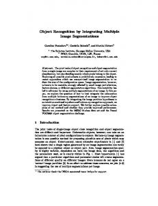
The goal of the object recognition system is to match assemblies of recovered volumes to models in the object database. Given a database of object models representing the domain of a recognition task, we seek a set of threedimensional volumetric modeling primitives that, when assembled together, can be used to construct the object models. To demonstrate our approach to object recognition, we have selected an object representation similar to that used by Biederman �Bie85], in which the Cartesian product of contrastive shape properties gives rise to a set of volumetric primitives called geons. For our investigation, we have chosen three properties including cross-section shape, axis shape, and cross-section size variation (Dickinson et al. �DPR90]). The values of these properties give rise to a set of ten volumes (a subset of Biederman's geons), modeled using Pentland's SuperSketch 3-D modeling tool �Pen86], and illustrated in Figure 1(a). To construct objects, the volumes are attached to one another with the restriction that any junction of two volumes involves exactly one distinct surface from each volume. To recover the volumetric primitives from an image, we need some way of modeling their appearance in the image. Traditional aspect graph representations of 3-D objects model an entire object with a set of aspects, each de ning a topologically distinct view of an object in terms of its visible surfaces �KvD79]. Our approach di ers in that we use aspects to represent a (typically small) set of volumetric primitives from which each object in our database is constructed, rather than representing an entire object directly. Consequently, our goal is to use aspects to recover the 3-D volumes that make up the object in order to carry out a recognition-by-parts procedure, rather than attempting to use aspects to recognize entire objects. The advantage of this approach is that since the number of qualitatively di erent volumes is generally small, the number of possible aspects is limited and, more important,
Primitives Links indicate possible parent primitives of aspects
Aspects Links indicate possible parent aspects of faces
Aspect Hierarchy
Faces Links indicate possible parent faces of boundary groups
Boundary Groups
(a)
(b)
Figure 1: (a) The Ten Volumetric Modeling Primitives, (b) The Aspect Hierarchy independent of the number of objects in the database. The disadvantage is that if a volume is occluded from a given
3-D viewpoint, its projected aspect in the image will also be occluded. Thus we must accommodate the matching of occluded aspects, which we accomplish by use of a hierarchical representation we call the aspect hierarchy. The aspect hierarchy consists of three levels, consisting of the set of aspects that model the chosen volumes, the set of component faces of the aspects, and the set of boundary groups representing all subsets of contours bounding the faces. Figure 1(b) illustrates a portion of the aspect hierarchy. The ambiguous mappings between the levels of the aspect hierarchy are captured in a set of conditional probabilities (Dickinson �Dic91]), mapping boundary groups to faces, faces to aspects, and aspects to volumes. These conditional probabilities result from a statistical analysis of a set of images approximating the set of all views of all the volumes. 2.2
Qualitative Shape Recovery
Qualitative shape recovery is a process that takes as input a single image and generates a viewer-centered representation of the image called the image model. The image model is a repository or database that maps pixels in the image to recovered qualitative volumes. In addition, the image model maps volume classes to recovered volume instances in the image. The image model thus supports queries of the form: \What recovered volumes occupy the pixel (x,y) in the image?" And: \Get me all volumes in the image of type ." The qualitative shape recovery pipeline is depicted in Figure 2 each of the left and right channels from the stereo head has its own dedicated pipeline, resulting in the maintenance of a left and a right image model. The process has two major components. First, the image is preprocessed to extract a face topology graph, in which nodes represent segmented image regions and arcs specify region adjacency. Each node (region) contains a list of face hypotheses or shape interpretations of the region in terms of the faces in the aspect hierarchy. Details of the region segmentation and face labeling processes can be found in �DPR92b]. Given a face topology graph representation of the input region, the next step in the qualitative shape recovery process is the grouping of faces into part-based aspects. Shape recovery may proceed in a bottom-up or top-down manner. In a bottom-up shape recovery mode, the system has no prior expectation of image content. Faces enter the bottom of the aspect hierarchy and, through an inference process that exploits the conditional probabilities linking together the levels of the aspect hierarchy, qualitative volumes come out the top. In a top-down shape recovery mode, the system is searching for a particular object or component volume. Target volumes enter the top of the aspect hierarchy and, through an attention process that also exploits the conditional probabilities, a constrained
left face topology graph left image
preprocess image
recover qualitative shape
left qualitative volumes
left image model
acquire images
right image preprocess image
right face topology graph
recover qualitative shape
right qualitative volumes
right image model
Figure 2: Qualitative Shape Recovery left image model
left volume
recover quantitative shape
right image model
fitted volume
world model
right volume
Figure 3: Quantitative Shape Recovery volume recovery process is focused at key points in the image. Details of the qualitative shape recovery process can be found in Dickinson et al. �DPR92b, DPR92a, DP92]. 2.3
Quantitative Shape Representation
The left and right image models represent a coarse or qualitative interpretation of the left and right images, respectively, in terms of a set of qualitatively-de ned volumetric parts. As mentioned earlier, the image models support image-based queries such as \what object am I pointing to?" or \show me the blocks in the image." Although this representation may be su�cient for labeling the image in terms of 3-D qualitative volumes, actual manipulation of the objects (if necessary) requires a more explicit representation capturing quantitative shape as well as pose (position and orientation). The nal stage of the recognition pipeline, as shown in Figure 3, uses corresponding qualitative volumes from the left and right image models to constrain the tting of a deformable model to the image data. The resulting quantitative model captures the ne shape and pose of the object supporting manipulation. Based on the vocabulary of shapes we want to recover, we quantitatively model our volumetric parts using
superquadric ellipsoids �Bar81], which are given by the following formula:
0aC C 1 e = a @ a2C S u u
1 1
a3Su 1
v
v
2 2
1 A�
(1)
where ;�=2 � u � �=2 and ;� � v < �, and where Sw = sgn(sin w)j sin wj , and Cw = sgn(cos w)j cos wj . Here, a � 0 is a scale parameter, 0 � a1� a2� a3 � 1 are aspect ratio parameters, and �1� �2 � 0 are \squareness" parameters. We then combine linear tapering along principal axes 1 and 2, and bending along principal axis 3 of the superquadric e1 into a single parameterized deformation T, and express the reference shape as:
0( s = T(e� t1� t2� b1� b2� b3) = @ (
t1 e3 aa3 w t2 e3 aa3 w
+ 1) e1 + b1 cos( eaa3 +3bw2 �b3 ) + 1) e2
1 A�
(2) e3 where ;1 � t1 � t2 � 1 are the tapering parameters in principal axes 1 and 2, respectively b1 de nes the magnitude of the bending and can be positive or negative ;1 � b2 � 1 de nes the location on axis 3 where bending is applied and 0 < b3 � 1 de nes the region of in�uence of bending. Our method for incorporating global deformations is not restricted to only tapering and bending deformations. Any other deformation that can be expressed as a continuous parameterized function can be incorporated as our global deformation in a similar way. We collect the parameters in s into the parameter vector:
qs = (a� a1 � a2� a3� �1� �2� t1� t2 � b1� b2� b3)> :
(3)
The above global deformation parameters are adequate for quantitatively describing the ten volumetric modeling primitives shown in Figure 1(a). 2.4
Quantitative Shape Recovery
In this section, we brie�y review the quantitative shape recovery process further details can be found in �DM92, MD93]. The rst step in recovering the quantitative shape corresponding to a qualitative volume is to identify corresponding volumes in the left and right image models. A pair of volumes represents a correspondence if: (i) the volumes have the same label, (ii) their aspects have the same label, and (iii) the ratio of the vertical intersection of the bounding rectangles of the two volumes to the vertical size of each bounding rectangle exceeds some threshold (epipolar constraint). Intuitively, volumes from the left and right image are said to correspond if they are of the same type, they are viewed in roughly the same orientation, and their vertical disparity is small. Given a pair of corresponding volumes, a superquadric ellipsoid is independently tted to the contours of each volume. When tting the model to visual data, our goal is to recover q, the vector of degrees of freedom of the model. The components qc (position of model center) and q� (orientation of model) are the global rigid motion coordinates, and qs are the global deformation coordinates. Our approach carries out the coordinate tting procedure in a physically-based way. We make our model dynamic in q by introducing mass, damping, and a deformation strain energy. This allows us, through the apparatus of Lagrangian dynamics, to arrive at a set of equations of motion governing the behavior of our model under the action of externally applied forces. The Lagrange equations of motion take the form �TM91]: Mq� + Dq_ + Kq = fq � (4) where M, D, and K are the mass, damping, and sti ness matrices, respectively, and where fq (u� t) are the generalized external forces associated with the degrees of freedom of the model. In the dynamic model tting process, the contour data belonging to a recovered qualitative volume are transformed into an externally applied force distribution f (u� t). We convert the external forces to generalized forces fq which act on the generalized coordinates of the model �TM91]. We apply forces to the model based on di erences between the model's projection in the image and the image data. Each of these forces corresponds to the appropriate generalized coordinate that has to be adapted so that the model ts the data. Given that our vocabulary of volumetric primitives 1
These coincide with the model frame axes
x y
and respectively z
is limited, we devise a systematic way of computing the generalized forces for each volume. The computation depends on the in�uence of particular parts of the projected image on the model degrees of freedom. Such parts correspond to the image faces (grouped to form an aspect) provided by the qualitative shape extraction. In the case of occluded volumes, resulting in both occluded aspects and occluded faces, only those portions (boundary groups) of the faces that were used to de ne the faces exert external forces on the models. When tting models independently to the left and right qualitative volumes, the depth of the model must be chosen arbitrarily. The nal step solves speci cally for the depth and scale of the model and allows both qualitative volumes to simultaneously a ect the shape of a single quantitative model. Speci cally, given two quantitative model instances, mL and mR , one per image, and having the same scale, choose one of the images, say R, and project the locations of the left and right model centers, mLc and mRc , into R. Let the locations of these projected model centers be cL and cR respectively. We then map the di erence in the x coordinates2 of cL and cR into a force that modi es mL and mR in the direction of mL and mR , respectively, according to the following formula: k m_ k = sjcLx ; cRx j km mk
(5)
k
where k = L or k = R, s = 1 if cLx < cRx , and s = ;1 otherwise. Once cL = cR , we rst sum the forces that the left and right image data exert on the model. From their sum, we then compute the generalized force fqa that corresponds to the scaling parameter a in equation (1), and using equation (4), we modify a. 2.5
Recognition Control
Each component of the recognition pipeline is implemented as an independent process that reacts to outputs at its previous stage. There are identical processes for the left and right channels of the initial sections of the pipeline the nal quantitative tting stage is a single process that reacts to the nal outputs from both the left and right channels. Images are acquired at video rates from the camera and are fed directly to a Datacube MaxVideo 20 system where successive images are compared at video rates. Image content may change due to motion in the image or due to egomotion of the head. If image content changes signi cantly between successive frames, then the preprocessing stage of the recognition pipeline reacts automatically by computing a new face topology graph based on the current image. The next stage in the pipeline, the qualitative volume extraction stage, senses the new face topology graph and responds by creating a new image model. Qualitative volumes are extracted from the new face topology graph and deposited into the new image model. Addition of a new qualitative volume in one (e.g., left) image model triggers the quantitative volume recovery stage to search for a corresponding volume in the other (in this case, right) image model. When it discovers a correspondence, it initiates the tting procedure to recover the quantitative shape of the pair of volumes. Each qualitative volume is assigned the same 3-D parameters following the tting step. The tted 3-D volume is then deposited into the world model. Note that objects put in the world model are persistent, while image model objects are lost when new images are required. The behavior of each stage in the recognition pipeline is controlled by a set of state variables. For example, in the qualitative volume extraction stage, state variables control whether the system is recovering volumes in a bottom-up or a top-down fashion, and whether the search spans the entire image or is focused at a particular location. In this way, we can support the four recognition behaviors outlined earlier. In addition, there are state variables that control the quality of the recovered volumes. For example, the system can be constrained to recover only high probability aspects in order to provide su�cient tting constraints on quantitative shape recovery. Alternatively, if no such aspects are found, the constraints can be weakened so that less likely aspects can be found these can then be used to drive an active scheme which will move the head to nd better aspects (Dickinson, Olofsson, and Christensen �DOC93]). In the same manner, there are state variables that control the behavior of the preprocessing stage (to a ect segmentation performance) and the quantitative shape recovery stage (to a ect tting performance). It is important to once again note that the pipeline is completely autonomous, i.e., it reacts to changes in its eld of view by attempting to recognize objects in the image according to one of the four behaviors it has been instructed to exhibit. At any time, the behavior may be externally changed, a ecting the objects that come out the end of the pipeline. In addition, the pipeline has no idea why an image may be changing and hence triggering the pipeline to recognize objects. It may be due to motion in the image or it may be due to some higher-level process moving the head around. 2
Since the two cameras are parallel, the projections of the two model frame centers di�er only in the direction. x
3 The Planner
The planner is another process whose main function, as shown in Figure 4, is to map high level recognition goals into pipeline control strategies that will successfully meet these goals. The planner can be autonomous or, in the case of PLAYBOT, can take high-level goals from the user. Even in the PLAYBOT system, the recognition behavior responsible for identifying and localizing all the objects in the world is a completely autonomous process which is pre-empted only by requests by the child. It is important to note that the planner does not have knowledge of the recognition pipeline internals nor is it responsible for executing its stages. Rather, it knows only how a particular set of state variables can be tuned to increase the probability of recognizing a given set of objects. To the planner, the recognition pipeline is a black box with images coming in one end, objects coming out the other, and a few switches on the side which govern what comes out. The planner controls the behavior of the recognition pipeline, a ecting the images that enter the pipeline by having direct control over head movement, and controlling the objects that come out of the back end of the pipeline by setting the state variables that govern the recognition behaviors. For example, if the user wants an instance of a particular class of object and none have been deposited into the image (2-D) or world (3-D) models, then the planner can change the state of the recognition pipeline, e ectively \tuning" it to search for a particular class of object. Alternatively, if the system is already tuned to nd that object, it can relax some of the quality constraints (in the form of state variables) to nd weaker instances of the object from which it can direct the head to improve their interpretation. Finally, if the planner is convinced that the object is not in the eld of view, it can direct the head to some other location in the world, gating new images into the pipeline, and observing which objects come out the other end (world model).
4 Experiments We are in the process of building a prototype of the architecture to support the PLAYBOT application described earlier. The system runs on a SGI IRIS (4 processor) computer with a separate processor for each channel of the recognition pipeline, one for the quantitative shape recovery stage, and one for the planner and user interface. Each stage of the recognition pipeline, along with the planner and user interface are implemented as separate UNIX processes. At this time, only two of the four high-level recognition behaviors are supported, namely the unconstrained top-down and constrained bottom-up behaviors. Furthermore, the initial prototype does not not support feedback within the recognition pipeline. Finally, the planner has no control over the head at the present time, although it does control image acquisition. The user interface to the PLAYBOT system is shown in Figure 5. At the top, separate panes show the images from the left and right cameras (in this case, images of an example con guration of the PLAYBOT tabletop). At the bottom left is the rendered contents of the world model. The user can move through the world model under mouse control, allowing the user to view recovered objects from any viewing position. Next to the world model display are two panes of icons. The upper pane speci es all the objects the system is able to recover and recognize. In the prototype system, these objects correspond to the ten volumes shown in Figure 1(a). Below the object icons are the command icons specifying the various actions that can be requested by the user. This initial set of commands, which does not support any object manipulation, can be divided into two groups: the Find commands and the Identify commands. The Find commands take an object name or icon, and trigger a search for an object of that type in the world. If the object is found in the world model, it is highlighted in the world model display. If the object is found in the image model, i.e., it is visible in one of the image panes, it is highlighted in the image. In either case, if the highlighted object is not the object the user intended the system to nd, then the user can execute the \Redo Last Command" which will look for the next best instance of the object in the world (or image). In Figure 5, each of the left and right image panes have a highlighted block resulting from a sequence of two \Find block" commands. The rst block the system found was contained in the left image while the second instance was found in the right image. (Searching for an object will result in queries sent to both image models.) The world model display shows the results of the tting process applied to the two corresponding volumes. The Find commands represent the only way the user can reference an object that is not in the eld of view. However, if the object is in the eld of view (contained in one of the images), or if it has been previously recovered and appears in the world model, then the user interface supports a more direct interface. The Identify commands allow the user to point to either image pane or to the world model display pane and have the system identify the object at the mouse location and highlight it. As with a Find command, if the identi ed object is not the interpretation
USER INTERFACE
PLANNER
State Variables
preprocess image
left face topology graph
left image
left qualitative recover volumes qualitative shape
left image model
left volume fitted volume recover quantitative shape
acquire images right image preprocess image
right face topology graph
right qualitative recover volumes qualitative shape
right image model
right volume
RECOGNITION PIPELINE Figure 4: The Planner
world model
Figure 5: Finding an Object
the user is looking for, then \Redo Last Command" can be invoked to enumerate any other interpretations of a particular region in the image. In Figure 6, the mouse was clicked on the tall block in the right image. The block is highlighted and its type is indicated in a message to the user.
5 Conclusions For a mobile robot to move through its environment, recognizing and manipulating a variety of objects, it must be equipped with an object recognition system that supports a variety of object recognition behaviors. In this paper, we have proposed an architecture consisting of an autonomous recognition pipeline which can support four di erent behaviors. Choosing which behavior the pipeline should exhibit is the responsibility of the planner whose responsibility is to satisfy the high-level recognition goals. The recognition pipeline has no concept of a moving head or high-level recognition goals it simply tries to recognize objects in its eld of view. It is the responsibility of the planner to intelligently move the head around and dictate the recognition behavior exhibited by the pipeline. The two-layer architecture we propose extends Brooks' subsumption scheme, overcoming the scaling problem and addressing a much more complex recognition task.
References �Bar81] �Bie85] �Bro86] �Bro91a] �Bro91b] �Con89] �Dic91] �DM92] �DOC93] �DP92] �DPR90] �DPR92a] �DPR92b]
A. Barr. Superquadrics and angle-preserving transformations. IEEE Computer Graphics and Applications, 1:11{23, 1981. I. Biederman. Human image understanding: Recent research and a theory. Computer Vision, Graphics, and Image Processing, 32:29{73, 1985. R. Brooks. A layered intelligent control system for a mobile robot. IEEE Journal of Robotics and Automation, RA-2:14{23, April 1986. R. Brooks. Intelligence without reason. In Proceedings, IJCAI, pages 569{595, Sydney, August 1991. R. Brooks. Intelligence without representation. Arti�cial Intelligence, 47:139{159, 1991. J. Connell. A colony architecture for an arti cial creature. Technical Report AI-TR 1151, Arti cial Intelligence Laboratory, Massachusetts Institute of Technology, 1989. S. Dickinson. The recovery and recognition of three-dimensional objects using part-based aspect matching. Technical Report CAR-TR-572, Center for Automation Research, University of Maryland, 1991. S. Dickinson and D. Metaxas. Using qualitative shape to constrain deformable model tting. In Proceedings, Sensor Fusion V, SPIE OE/Technology '92, Boston, MA, November 1992. S. Dickinson, G. Olofsson, and H. Christensen. Qualitative prediction in active recognition. In Proceedings, 8th Scandinavian Conference on Image Analysis (SCIA), Troms!, Norway, May 1993. S. Dickinson and A. Pentland. A uni ed approach to the recognition of expected and unexpected geonbased objects. In Proceedings, SPIE Applications of AI X: Machine Vision and Robotics, special session on \Recognition by Components", Orlando, FL, April 1992. S. Dickinson, A. Pentland, and A. Rosenfeld. A representation for qualitative 3-D object recognition integrating object-centered and viewer-centered models. In K. Leibovic, editor, Vision: A Convergence of Disciplines. Springer Verlag, New York, 1990. S. Dickinson, A. Pentland, and A. Rosenfeld. From volumes to views: An approach to 3-D object recognition. CVGIP: Image Understanding, 55(2):130{154, 1992. S. Dickinson, A. Pentland, and A. Rosenfeld. 3-D shape recovery using distributed aspect matching. IEEE Transactions on Pattern Analysis and Machine Intelligence, 14(2):174{198, 1992.
Figure 6: Identifying an Object
�KvD79] J. Koenderink and A. van Doorn. The internal representation of solid shape with respect to vision. Biological Cybernetics, 32:211{216, 1979. �MD93] D. Metaxas and S. Dickinson. Integration of quantitative and qualitative techniques for deformable model tting from orthographic, perspective, and stereo projections. In Proceedings, Fourth International Conference on Computer Vision, Berlin, Germany, May 1993. �Pen86] A. Pentland. Perceptual organization and the representation of natural form. Arti�cial Intelligence, 28:293{331, 1986. �TM91] D. Terzopoulos and D. Metaxas. Dynamic 3D models with local and global deformations: Deformable superquadrics. IEEE Transactions on Pattern Analysis and Machine Intelligence, 13(7):703{714, 1991. �Tso89] J. Tsotsos. The complexity of perceptual search tasks. In Proceedings, IJCAI, pages 1571{1577, Detroit, 1989. �Tso90] J. Tsotsos. A complexity level analysis of vision. Behavioral and Barin Sciences, 13(3):423{455, 1990. �Tso92a] J. Tsotsos. On behaviorist intelligence and the scaling problem. Technical Report RBCV-TR-92-42, Department of Computer Science, University of Toronto, September 1992. �Tso92b] J. Tsotsos. On the relative complexity of active vs passive visual search. International Journal of Computer Vision, 7(2):127{141, 1992.