M.A.Sc., Computer Networks, Ryerson University, 2005. Although ...... To repair the route after receiving RERRs, the node performs a new route discovery.
INTEGRATING UMTS AND MOBILE AD HOC NETWORKS by Meng-chieh Wu B.Sc. in Computer Engineering and Information Science Tunghai University, Taiwan, 1999
A thesis presented to Ryerson University to the in partial fulfillment of the requirements for the degree of Master of Applied Science in the Program of Computer Networks
Toronto, Ontario, Canada, 2005 ©Meng-chieh Wu 2005
Author’s Declaration I hereby declare that I am the sole author of this thesis. I authorize Ryerson University to lend this thesis to other institutions or individuals for the purpose of scholarly research.
_________________________________
I further authorize Ryerson University to reproduce this thesis by photocopying or by other means, in total or in part, at the request of other institutions or individuals for the purpose of scholarly research.
_________________________________
ii
Abstract Meng-chieh Wu, Integrating UMTS and Mobile Ad hoc Networks. M.A.Sc., Computer Networks, Ryerson University, 2005. Although cellular networks such as GPRS (2.5G) or UMTS (3G) have achieved providing both circuit-switching and packet-switching services with wide area coverage, the mobile users are still expecting higher data rates and more mobility to satisfy their needs. Integrating current network architecture with other high-speed and low-cost wireless technologies is a key challenge for migrating to 4G. The IEEE 802.11 technology which has been well-developed and widely-used in local area networks seems to be a proper choice for fulfilling users’ expectations. Its ad hoc functionality further improves the mobility of the users. This research proposes an architecture to achieve the internetworking between 802.11 Mobile Ad Hoc Network (MANET) and UMTS.
The key approach being applied for
intersystem handovers is SGSN signaling and for ad hoc mobility management is the Mobile IP signaling. The main purpose of this research is to retrieve the best effects by integrating these two network technologies. The integration system results several important features: wide area coverage, mobility and quality of service management.
iii
Acknowledgements
I am grateful to my supervisor, Dr. Muhammad Jaseemuddin, for his guidance and assistance throughout this research. The suggestions and ideas Dr. Jaseemuddin raised during our meetings were highly beneficial and very much appreciated. Also I would like to thank Dr. Bobby Ma for his advice and support; fellow research students, Amir Esmailpour and Arun Nanthakumaran, for their time they gave to provide feedback and recommendations on this thesis. Finally, I want to give my gratitude to my family, who always support and encourage me.
iv
Contents Contents
v
Tables
vii
Figures
viii
Chapter 1 Introduction
1
Chapter 2 Literature Review
5
2.1
Universal Mobile Telecommunication System
5
2.1.1
Overview
5
2.1.2
Core Network Domain
6
2.1.3
UMTS Terrestrial Radio Access Network Domain
6
2.1.4
User Equipment Domain
7
2.1.5
UMTS Signal Flows
7
2.1.6
UMTS Quality of Services
9
2.1.7
Inter-SGSN Routing Area Update
10
2.2
Mobile IP
12
2.3
Mobile Ad Hoc Network
13
2.3.1
Network Discovery
13
2.3.2
Routing
17
2.4
Global Connectivity for Ad Hoc Networks
20
2.4.1
Globalv4
20
2.4.2
MIPMANET
20
2.4.3
Globalv6
21
Chapter 3 Design of Integrating UMTS and Ad Hoc
v
Networks
22
3.1
Design Overview
22
3.2
Design Issues and Proposed Solutions
24
3.2.1
Mobile Node
24
3.2.2
Signaling between UMTS and Ad Hoc Networks
25
3.2.3
Addressing
27
3.2.4
Ad Hoc Network Mobility Management
29
3.2.5
Inter-System Handovers
34
3.2.6
Multiple Gateways
38
Chapter 4 Simulation and Results
41
4.1
Overview
41
4.2
Simulation Design
41
4.2.1
Simulation Architecture
41
4.2.2
Simulation Components
42
4.2.3
Simulation Tests
51
Simulation Results
54
4.3
4.3.1
Handover Time
54
4.3.2
Throughput
56
4.3.3
Packet Loss
60
Chapter 5 Conclusion and Future Directions
63
Appendix A – Acronyms used in this thesis
65
Appendix B – OPNET Model List
67
Bibliography
68
vi
Tables Table 1 UMTS QoS classes ............................................................................................9 Table 2 Functionality List for Each Simulation Component .........................................42 Table 3 Simulation Properties......................................................................................51 Table 4 Application Profile ...........................................................................................53 Table 5 CBR Application..............................................................................................53 Table 6 File Transfer (Heavy) Application .....................................................................53 Table 7 Handover Time Measure Points .......................................................................54
vii
Figures Figure 1 Basic Concept .................................................................................................3 Figure 2 Features of UMTS Interface and 802.11 Ad Hoc Interface ................................3 Figure 3 UMTS Network Architecture ............................................................................6 Figure 4 UMTS Signal Flows..........................................................................................8 Figure 5 Inter-SGSN Routing Area Update...................................................................11 Figure 6 Mobile IP – Triangular Routing Scenario ........................................................12 Figure 7 ESS and BSS.................................................................................................14 Figure 8 IBSS ..............................................................................................................14 Figure 9 802.11 Beacon Frame Format .......................................................................16 Figure 10 802.11 Probe Request Frame Format...........................................................16 Figure 11 802.11 Probe Response Frame Format .......................................................16 Figure 12 AODV Routing .............................................................................................18 Figure 13 AODV – Link Break......................................................................................19 Figure 14 AODV – Local Repair ...................................................................................19 Figure 15 Network Structure .......................................................................................23 Figure 16 Mobile Node Structure .................................................................................25 Figure 17 Network Architecture – IP Signaling .............................................................26 Figure 18 Network Architecture – SGSN Signaling .......................................................27 Figure 19 Addressing and Tunneling ...........................................................................28 Figure 20 Packet Forwarding Flow within Ad Hoc Networks.........................................30 Figure 21 Example of the local route and the route through gateway...........................32 Figure 22 Scenario 1 – Internet to Ad Hoc ...................................................................33 Figure 23 Scenario 2 – Ad Hoc to Internet ...................................................................33 Figure 24 Scenario 3.1 – Ad Hoc to Ad Hoc when destination is known .......................33 Figure 25 Scenario 3.2 – Ad Hoc to Ad Hoc when destination is unknown ...................34 Figure 26 UMTS – MANET Handover ...........................................................................36 Figure 27 MANET – UMTS Handover ...........................................................................37
viii
Figure 28 Single or Multiple Gateways (Tunnel End Point: MN) ...................................39 Figure 29 Single or Multiple Gateways (Tunnel End Point: Gateway) ...........................40 Figure 30 Theoretical Simulation Architecture.............................................................41 Figure 31 Simulation Architecture in OPNET...............................................................42 Figure 32 OPNET Mobile Node Model ..........................................................................43 Figure 33 OPNET Mobile IP MN Process Model ............................................................44 Figure 34 OPNET GMM Process Model ........................................................................44 Figure 35 OPNET Gateway Node Model .......................................................................45 Figure 36 OPNET GTP Process Model ..........................................................................46 Figure 37 OPNET Mobile IP Agent Process Model.........................................................47 Figure 38 OPNET SGSN Process Model........................................................................48 Figure 39 OPNET UMTS—MANET Handover................................................................49 Figure 40 OPNET MANET—UMTS Handover................................................................50 Figure 41 Trajectory in OPNET ....................................................................................52 Figure 42 Table of Trajectory .......................................................................................52 Figure 43 Timeline vs. Trajectory.................................................................................52 Figure 44 UMTS—MANET Handover Time ...................................................................56 Figure 45 MANET—UMTS Handover Time ...................................................................56 Figure 46 Overlaid Statistics of UMTS and MANET Throughputs (File Size: 30,000bytes) ............................................................................................................................58 Figure 47 Overlaid Statistics of UMTS and MANET Throughputs (File Size: 85,000bytes) ............................................................................................................................58 Figure
48
Overlaid Statistics
of
UMTS
and
MANET
Throughputs
(File
Size:
200,000bytes) ......................................................................................................59 Figure 49 Overlaid Statistics of UMTS and MANET Throughputs (File Size: 85,000bytes) when 2 mobile nodes are moving in ad hoc network.............................................59 Figure 50 Overlaid Statistics of UMTS and MANET Throughputs (File Size: 85,000bytes) when 5 mobile nodes are moving in ad hoc network.............................................60 Figure 51 Packet Loss during UMTS—MANET Handover .............................................62 Figure 52 Packet Loss during MANET—UMTS Handover .............................................62
ix
Chapter 1 Introduction
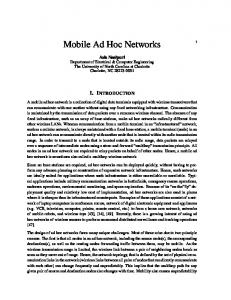
As the exponential growth of the Internet technologies, we can easily observe that wireless networking is the most attractive trend that has been discussed and developed for over decades. The significant change is mobility. Internet Users are no longer sitting in front of desktops; instead, carrying wireless mobile devices connecting to the Internet has become to a new phase of network communication. The desire behind this evolution is to build up an ultimate environment for Internet access and achieve the convenience and the flexibility for life. Two major wireless technologies nowadays are cellular networks and wireless local area networks (WLANs). In cellular network, wide area coverage is achieved by dividing the whole area into cells whose sizes are determined by the transmission ranges of radio base stations. With the introduction of GPRS into GSM network, cellular networks have been able to support both voice and data communications. The GSM evolved into 3G UMTS network standardized by 3GPP [1]. The data transmission rates in UMTS are able to go up to 2Mbps in the best case. Although it is substantial improvement from 2G system achieved through significant advancement of wireless technology, it still falls short of matching the speed of 100 Mbps Ethernet LAN. The emerging standard of wireless LAN, e.g. standard IEEE 802.11a with up to 54Mbps data rate, is widely considered as the technology that can bridge the gap between the wired and wireless technologies. Wireless LAN is suitable for short range coverage, which makes it ideal for hotspots and the areas of high activities. The combination of cellular and wireless LAN enables wireless communications to achieve high transmission rates in wide area coverage. Several architectures of integrating UMTS and 802.11 WLAN networks have been proposed [9], [13] and [15]. In [9], the integration is proposed to establish the connection between UMTS core network (CN) and 802.11 Access Points (APs) attached to a border router (BR) and to utilize both UMTS and WLAN connections when mobile
1
hosts are located in both UMTS macro cell and WLAN micro cell.
In hot spot scenario,
the 802.11 connection can be turned on to serve for the applications that require highspeed connectivity. Figure 1 depicts a scenario that illustrates the basic concepts of this architecture. First the mobile node is powered up in a UMTS cell and establishes connection with UMTS network. Then, it moves to an area where it can receive 802.11 beacons indicating that 802.11 service is available. Finally, the mobile node connects to 802.11 network and hands over some services to the 802.11 network to achieve higher data rate as required by some applications. In this scenario, mobile nodes are equipped with two interfaces – a UMTS interface and a WLAN interface. Figure 2 lists some features for each interface. The integration system is trying to establish both connections and achieve the best performance by utilizing the advantages of both methods and compensate the disadvantage of the individual method.
Internet
Internet
on ne ctio n
CN
UM T
SC
on ne ctio n
CN
UMTS BS
UM T
SC
802.11 AP
UMTS BS
802.11 AP
802 .11 Ad Hoc Beacon
ON UMTS Interface OFF 802.11 Interface
ON UMTS Interface !!!
802 .11 Interface
Internet
UM T
SC on ne ctio n
CN
UMTS BS
80 2.1 1
Co n
ne c ti on
802.11 AP
ON UMTS Interface ON 802 .11 Interface
2
Figure 1 Basic Concept
• • • • • • • •
Always on 32~384 kbit/s Cellular, wide coverage Circuit and packet switched Services High Mobility, global Telecommunication Licensed Expensive
• • • • • • • • •
UMTS interface
On if WLAN is detected Ad hoc mode or Dual mode Packet switched Services 32 k ~ 56M bits/s Non-cellular , local coverage Low mobility, local, hot spot Data communication No license Inexpensive
802.11 interface
Figure 2 Features of UMTS Interface and 802.11 Ad Hoc Interface
The IEEE 802.11 technology also provides ad hoc mode of operation in addition to the infrastructure mode. Mobile Ad Hoc Networks (MANETs) [14] are characterized by infrastructure-less configuration and on-demand routing. A mobile node in MANET acts both as a router to forward the packets and as a host to generate the packets. Multihop communication in MANET further enhances the networking environment where users can access to the Internet anywhere at anytime through their neighbors. In this thesis we proposed a design for integrating UMTS and MANET. Our design is based on the architecture proposed in [9]. We assumed that a mobile node is equipped with two interfaces – a UMTS interface and a MANET interface. We considered MANET is connected to UMTS CN and integrated at Gateway GPRS Support Node (GGSN). We developed vertical handover scheme for a mobile node to move from UMTS to MANET and vice versa. We addressed the issue of signaling and Quality of Service during the intersystem handover. We developed a simulation model of the integrated system in OPNET network simulator. We evaluated the performance of the integrated system under variety of scenarios. In our design, we introduced a gateway in MANET, which is connected with the UMTS CN. The gateway communicates with GGSN using the GTP protocol standardized by 3GPP [1]. We modeled the intersystem handover as inter-SGSN handover. Hence the
3
gateway performs identical to SGSN functionality and employs inter-SGSN signaling for the handover. We also presented a design to address multiple gateway situations. The whole purpose of this research relates to the idea of improving data transmission rates and mobility in existing wide area network (UMTS) for mobile hosts in an ad hoc network to enjoy the connectivity from both networks and be able to switch some types of services (i.e. packet data service). This thesis is organized as follows: Chapter 2 provides a literature review of ad hoc network, UMTS, Mobile IP and recent researches related to our design. Chapter 3 describes the design issues and proposed solutions, which focus on inter-system handover and mobility in ad hoc networks. In Chapter 4 , the simulation models and results are given. Finally the conclusions and future directions of this research are given in Chapter 5 .
4
Chapter 2 Literature Review 2.1
Universal Mobile Telecommunication System
2.1.1 Overview Universal Mobile Telecommunication System (UMTS) is one of IMT-2000 standards that are defined to provide true third generation (3G) service to wide range of global users in the near future. It represents an evolution in terms of data services and speeds of today’s
2.5G
technology, General
Packet Radio
Service
(GPRS). The
network
architecture consists of three domains: User Equipment (UE) domain, UMTS Terrestrial Radio Access Network (UTRAN) domain, and core network (CN) domain. UMTS network architecture is shown in Figure 3.
Packet-Switched
UE
External Packet Switched Network
Node B
RNC
SGSN
GGSN
Node B UE
HLR
External Circuit Switched Network
Node B
UE
RNC
MSC/VLR
Node B
User Equipment (UE) Domain
Uu
UMTS Terrestrial Radio Network (UTRAN) Domain
GMSC Circuit-Switched
Core Network (CN) Domain
Iu
5
Figure 3 UMTS Network Architecture
2.1.2 Core Network Domain UMTS network supports both circuit-switching and packet-switching with special nodes in the Core Network (CN). The CN consists of two separate networks for circuitswitching and packet-switching as shown in Figure 3. The circuit-switched (CS) network is based on the existing GSM networks. In this research, the discussion will be focused on packet-switched (PS) network shown in the top-right part of Figure 3 since we do not handle the handover of CS traffic. Three important core equipments and their functionalities are listed below: •
Home Location Register (HLR): When a node establishes a connection with UMTS network, the user data and associated information such as authorizations and keys are stored in a database, called Home Location Register (HLR). An incoming call or packet from extended networks can be forwarded according to the information in HLR indicating in which part of mobile radio network a user is currently operating.
•
Serving GPRS Support Node (SGSN): The Serving GPRS Support Node (SGSN) is a switching node that supports packet-switching connections. It is the GPRS interface with UTRAN (Radio Network) through RNC. It also maintains user mobility by storing the current position of the user. An incoming data packet from the Internet can be routed to the user from SGSN.
•
Gateway GPRS Support Node (GGSN): The gateway to other packet-switching networks such as the Internet is called Gateway GPRS Support Node (GGSN). The incoming packets from other networks are tunneled from GGSN using tunneling Protocol (GTP).
2.1.3 UMTS Terrestrial Radio Access Network Domain UMTS Terrestrial Radio Access Network (UTRAN) is responsible for the radio resource management. The following are the nodes in a UTRAN: •
Radio Network Controller (RNC): The Radio Network Controller (RNC) is the central node in a UTRAN. It handles the tasks related to data transmission over the radio interface such as resource assignments and intra RNC handovers.
6
•
Node B: The base transceiver stations in UMTS are denoted Node Bs. A Node B provides the radio connections for the mobile nodes within one or several cells with its antenna system.
2.1.4 User Equipment Domain User Equipment domain contains User Equipments (UEs). •
User Equipment (UE): A User Equipment (UE) is also referred to a user terminal. It participates in signaling for the connection setup and release. The example of an UE can be a mobile phone, a personal digital assistant (PDA) or a laptop. The terminal carries a UMTS Subscriber Identity Module (USIM) which contains all the necessary data for authentication and accessing the UMTS network in order to use services.
2.1.5 UMTS Signal Flows Figure 4 shows UMTS signal flows, including GPRS Attach, PDP Context Activation, and RAB Assignment procedures. The signal flows are illustrated in three different scenarios: 1) When the UE is powered up, it attaches to UMTS CN. After the Attach procedure is confirmed, the UE enters Connected state. 2) When a UE is ready to send an uplink packet data unit (PDU) for that the uplink connection is not yet established, it sends the Activate PDP Context Request to UMTS CN. The CN initiates the RAB setup procedure. After the RAB assignment is completed, the CN sends the Activate PDP Context Request Accepted back to the UE. At this point, the UE can start to forward uplink PDUs to the CN. 3) When a downlink PDU arrives the CN, the CN sends Request PDP Context Activation to pull the Activate PDP Context Request from the UE. The following processes are similar with the PDP activation and RAB setup in 2). Finally when PDP activation is completed, the CN start to forward downlink PDUs to the UE.
7
UE
RNC
CN
Power-up GPRS Attach GPRS Attach Accept Connected
GPRS Attach Complete
Uplink PDU Activate PDP Context Request RAB Assignment Request Admission Control Radio Bearer Setup Request Radio Bearer Setup Complete RAB Assignment Response Activate PDP Context Accept Uplink PDU
Downlink PDU Request PDP Context activation Activate PDP Context Request RAB Assignment Request
Radio Bearer Setup Radio Bearer Complete
RAB Assignment Response Activate PDP Context Accept Downlink PDU
Figure 4 UMTS Signal Flows
8
2.1.6 UMTS Quality of Services Third Generation Partnership Project, 3GPP, has defined a QoS framework [5] for UMTS network. The basic classes defined by UMTS/3GPP [1] are listed in Table 1. QoS Class
Type of Application
Example Applications
Characteristics
Conversationa
Real-time person-to-person
Audio voice
Low delay low jitter,
l
communication
Videophone
reasonable clarity and absence of echo
Streaming
Interactive
Real-time applications that
Video-on-demand
Low jitter and media
exchange information between
Live MPEG4 listening
synchronization.
viewer and listener without any
Web-radio,
Buffering can be applied so
human response
News streams
that delay is not a criterion
Multicasts.
anymore.
Humans or machines that
Online games
Tolerance to round-trip
interact with another device
Network management
delay and packet loss
(request-response pattern of
Systems polling
end-user)
Web-browsing Database retrieval
Background
All applications that receive
Emails
data passively or actively
Messaging
request it without any
File transfers
Data integrity
immediate need to handle this data
Table 1 UMTS QoS classes
In traditional IP network, packets carry Type of Service (ToS) values. When the packets are transmitted from the external IP network to the UMTS network, the selection of the class and appropriate traffic attribute values is made according to the mapping between IP based ToS and UMTS QoS. The ToS to QoS mapping can certainly be configured manually at the GGSN, which is the gateway to the packet network. The typical definitions of ToS to UMTS QoS mapping types are: Best Effort (ToS: 0) and Background traffic (ToS: 1) belong to Background class; Standard (ToS: 2) and Excellent Effort (ToS:
9
3) are categorized into Interactive class; Streaming Multimedia (ToS: 4) is mapped to Streaming class; at last, Interactive Multimedia (ToS: 5), Interactive Voice (ToS: 6) and Reserved (ToS: 7) are located in Conversational class.
2.1.7 Inter-SGSN Routing Area Update In UMTS, a routing area is defined as a collection of cells where a mobile node in STANDBY state does not inform SGSN the location changes when moving across the cells within a routing area. The routing area update takes place when a GPRS-attached MN detects that it has entered a new routing area. In Figure 5, the inter SGSN Routing Area Update [4] signaling is shown. The MN sends Routing Area Update Request to the new SGSN. Then the new SGSN sends SGSN Context Request to the old SGSN to get the PDP Context for this MN. The old SGSN responds with the PDP context information. The security function may be executed after this step. Then the new SGSN sends SGSN Context Acknowledge to the old SGSN, which indicates that the new SGSN is ready to receive data packets destined to the MN. The old SGSN starts forwarding packets to the new SGSN. Until this step, the packets from the Internet continue to traverse to the old SGSN. Hence, following this step, the GGSN is informed through Update PDP Context messages about the change of SGSN. Meanwhile, the HLR is also notified about this change. After completing location management procedure, the final step is to acknowledge and confirm the routing area update.
10
MN
BSS
New SGSN
Routing Area Update Request
Old SGSN
GGSN
SGSN Context Request SGSN Context Response
Security Fucntions SGSN Context Acknowledge Forward Pakcets Update PDP Context Request Update PDP Context Response Update Location Cancel Location Cancel Location Ack Insert Subscriber Data Update Location Ack Update Location Ack Routing Area Update Accept Routing Area Update Complete
Figure 5 Inter-SGSN Routing Area Update
11
HLR
2.2
Mobile IP
Mobile IP is the most useful protocol in the environments where mobility is desired and users can roam between different networks but still stay connected with the Internet. The ability of finding and changing the point of attachment to the Internet is the key technique in Mobile IP. When a correspondent node wants to communicate with a Mobile Node (MN) while it does not know the care-of address of the MN, it sends the packet to the MN’s Home Address. If the MN is located in the home network, it receives the packets through normal IP routing. However, if the MN is roaming outside of its home network, the Home Agent (HA) intercepts the packets, encapsulates them using the care-of address (CoA) information from its binding cache table and tunnels them to the visiting network where the MN is reached through the CoA. The MN either receives CoA through the Foreign Agent (FA) or gets its own CoA as a co-located CoA (CCoA). The MN decapsulates the packets it receives through the tunnel. On the return path, the MN sends packets directly to the Corresponding Node’s address.
This triangular routing
scenario is shown as Figure 6. The obvious drawback of triangular routing is that the shortest path routing is compromised. In order to deal with this issue, optimization is incorporated in Mobile IPv6 [10]. The MN can notify the correspondent node its care-of address therefore the correspondent node can forward the future packets directly to the care-of address. This removes the cost of triangular routing in terms of the waste of network bandwidth and the latency.
Foregin Network
Home Network
Foreign Agent
Internet
Mobile Node
Home Agent
Correspondent Node
Figure 6 Mobile IP – Triangular Routing Scenario
12
In Mobile IP networks, the mobility agents (HAs and FAs) periodically broadcast Router Advertisements (RAs). The MN detects its movement from one network to another through the network information contained in the RA. It can also configure a care-of address with the prefix for the network according to the RA it receives in the visiting network. Thus, the RAs assist in handover decisions when the MN moves from one network to another. For the HA to be able to forward the packets to a MN, the MN must periodically inform the HA its care-of address. These signaling messages containing CoA sent to the HA are called Binding Updates (BUs). The HA updates its binding cache as a result of processing the BUs. The MN keeps sending the BUs until it receives a Binding Acknowledgement (BA) from HA.
2.3
Mobile Ad Hoc Network
A Mobile Ad Hoc Network (MANET) is characterized by the lack of infrastructure for interconnecting the mobile nodes. The mobile node in MANET is capable of generating and receiving the packets as a host and also forwarding the packets as a router. Thus, the communication among the mobile nodes within MANET can be extended beyond their radio transmission ranges. In order to form the paths between any two nodes in the network, routing protocols designed for MANET are required to handle route discovery and maintenance. MANETs realize the idea of anytime and anywhere networks.
2.3.1 Network Discovery Two modes of operation are defined in IEEE 802.11 Wireless LAN (WLAN) standard – the infrastructure mode and the ad hoc mode. The 802.11 interface of a mobile node is configured to operate in one or the other mode. Some new interfaces provide automatic switching of mode after detecting the type of network. In 802.11 WLAN, beacons are used to allow mobile stations to find and identify a network and match parameters for joining the network. In IEEE 802.11 standard [8], a Basic Service Set (BSS) is a collection of Stations (STAs) that communicate with each other through an Access Point (AP) within an 802.11 WLAN. Each BSS has an AP, which defines its coverage area. A STA needs to associate with an AP for retrieving the network connectivity. An Extended Service Set (ESS)
13
consists of more than one BSS. The STAs can move from one BSS to another and reassociate with the new AP. In infrastructure mode (Figure 7), APs are periodically broadcasts beacons within a BSS. The beacon contains BSSID, which uniquely identifies a BSS. The BSSID field in the infrastructure mode is the MAC address of the AP, which forms the BSS. The STAs in the infrastructure mode only use the information in beacon frames if the BSSID is equal to the MAC address of the AP in the BSS.
Basic Service Set 1 (BSS1) Station D Station C Extended Service Set (ESS)
AP1 Distribution System
AP2
Station A Basic Service Set 2 (BSS2) Station B
Figure 7 ESS and BSS
Independent Basic Service Set (IBSS)
Station A
Station C
Station B
Figure 8 IBSS
14
A BSS can be formed without an AP, which is called an Independent Basic Service Set (IBSS), as illustrated in Figure 8. STAs within an IBSS should be able to communicate with each other without hidden node problem. The IBSS is the basic building block of an ad hoc network. In an IBSS, there is no access point. Thus, the beacon generation in an IBSS (ad hoc network) is distributed among the STAs. The first STA in an IBSS uses its own configured beacon interval to generate the beacon periodically, and also in the Probe Response frame. It announces the beacon interval in the beacon. Every STA that receives the beacon or probe response in the IBSS accepts the interval. Therefore every STA in the IBSS knows when the next beacon will be transmitted. At this time, each STA calculates a random “beacon backoff” interval and transmits its beacon if it has not received any other beacons before its beacon backoff interval expires [23]. During this beacon contention period, the data and other traffic related messages are halted. This mechanism ensures that there is always one beacon transmitted in the IBSS. The STA that has transmitted the last beacon responds the Probe Requests. Beacon, Probe Request and Probe Response are the 802.11 MAC frames [8]. The formats are shown in Figure 9, Figure 10, and Figure 11. The Probe Response frame is similar to the beacon frame, except that it does not carry Traffic Indication Map (TIM)1 and is sent in response to a Probe Request. A station may send a Probe Request to trigger a Probe Response when the station needs to obtain information from another station. The type and subtype fields in the Frame Control field together identify the function of the frame. Beacon, Probe Request and Probe Response all belong to type 00: Management frame. The subtypes are 1000 for beacon, 0100 for Probe Request, and 0101 for Probe Response. The Basic Service Set Identity (BSSID) field in the management frame and the Service Set Identity (SSID) field in the frame body indicate the identity of the ESS or IBSS. In the Management frames of subtype Probe Request, the BSSID is either a specific BSSID or the broadcast BSSID. Either an AP in a BSS or a STA in an IBSS send these three frames. The Capacity information field contains ESS and IBSS bits, which can be used to identify the network type (infrastructure network or ad hoc network). For an infrastructure network, the AP sends beacon or Probe Response with the ESS field 1 and the IBSS field 0. In an ad hoc network, the STAs send their beacon or Probe Response with the ESS field 0 and the IBSS field 1.
1
Traffic Indication Map (TIM). An access point periodically sends the TIM within a beacon to identify which
stations using power saving mode have data frames waiting for them in the access point's buffer. The TIM identifies a station by the association ID that the access point assigned during the association process.
15
Management Frame
MAC Header Frame Control
Protocol Type
Duration
Type
DA
SA
To DS
Subtype
From DS
Seq Control
BSSID
More Frag
Pwr Mgt
Retry
Frame Body
More Data
FCS
Order
Frame Control field
Time stamp
Beacon Interval
Capacity Information
Supported FH rates Para Set
SSID
DS Para Set
CF Para Set
IBSS Para Set
TIM
Beacon Frame Body field
ESS
CF Pollable
IBSS
CF Poll Request
Privacy
Reserved
Capacity Information field
Figure 9 802.11 Beacon Frame Format
Management Frame
MAC Header Frame Control
Protocol Type
Type
Duration
DA
To DS
Subtype
SA
From DS
Seq Control
BSSID
More Frag
Pwr Mgt
Retry
Frame Body
More Data
FCS
Order
Frame Control field SSID
Supported rates Probe Request Frame Body field
Figure 10 802.11 Probe Request Frame Format
Management Frame
MAC Header Frame Control
Protocol Type
Type
Duration
Subtype
DA
To DS
SA
From DS
Seq Control
BSSID
More Frag
Retry
Pwr Mgt
Frame Body
More Data
FCS
Order
Frame Control field
Time stamp
Beacon Interval
Capacity Information
SSID
Supported FH rates Para Set
DS Para Set
CF Para Set
IBSS Para Set
Probe Response Frame Body field
ESS
IBSS
CF Pollable
CF Poll Request
Privacy
Reserved
Capacity Information field
Figure 11 802.11 Probe Response Frame Format
16
2.3.2 Routing Route discovery and maintenance in ad hoc networks are more challenging than traditional fixed wired network or regular wireless local area networks due to the lack of fixed topology and the node mobility. The most significant difficulties that need to be overcome are: •
Periodical broadcast of route requests is required, but may result in the wastage of bandwidth.
•
Topologies may change frequently because the nodes can move and join or leave the networks. This makes it extremely hard to maintain the stable routes in the routing tables.
•
Power supply of each mobile node could affect the performance of its routing.
Many routing protocols have been proposed for ad hoc networks. They are classified into three categories: Proactive, Reactive, and Hybrid routing protocols. Proactive routing protocols are also known as table driven protocols. The routes are routinely discovered and maintained in case any packets need to be forwarded. Destinationsequenced Distance Vector (DSDR), Wireless Routing Protocol (WRP) and Fisheye State Routing (FSR) are examples of proactive routing protocols. Although this type of routing is most efficient in terms of delivering packets, the drawbacks are bandwidth consumed by the periodical flooding of route discovery messages and the wastage of memory space to store the complete routing table at every node in the network. In contrast, the reactive routing protocols invoked route discovery only when a route is needed. Route discovery can be completed by sending route requests and receiving replies before determining how to forward the data packets to the specified destinations. The routes can be cached to reuse for subsequent packets delivery. The routes are rediscovered if they are required after the expiry of the cached entries.
As compared to proactive
protocols, reactive protocols create much less overhead traffic; but the packet transmission delay may increase due to prior route setup. Route caching can be used to mitigate the delay. The popular reactive protocols are Ad hoc On-demand Distance Vector (AODV) [19] and Dynamic Source Routing (DSR) [11]. Hybrid routing protocols, such as Zone Routing Protocol (ZRP) [6], are designed to take advantage of both reactive and proactive routing. They divide the network into some sort of routing zones, and apply proactive routing among nodes within the zone, and perform reactive routing for inter-zonal traffic.
17
2.3.2.1
Ad Hoc On-demand Distance Vector (AODV)
AODV is a reactive protocol that only requires the route setup when it is needed. We discuss this in detail in this section because we will use AODV for our simulation in Chapter 4 . In AODV, the nodes periodically exchange Hello messages to maintain the connectivity with the neighbors in their transmission range. Figure 12 illustrates the route request procedure of AODV. To find a route, the originator broadcasts a route request (RREQ) to its neighbors. Intermediate nodes that have no information about this destination rebroadcast the request. Only the destination node or the intermediate nodes that have a fresh enough2 routing table entry for the destination reply the request by sending a route reply (RREP) along the reverse route.
Q 1. RRE
1. RRE Q
Intermediate node EP 2. RR
originator
2. RRE P
Intermediate node (knowing destination ) or destination itself
Figure 12 AODV Routing
In case of link break or destination unreachable, route errors (RERR) are sent to the neighbors to clean up invalid entries. Figure 13 illustrate the scenario when Node 2 detect the link with Node 4 has broken, it sends RERRs to inform its neighbours that Node 4 is currently unreachable. The neighbour nodes that receive the RERRs clean up the entries related to this unreachable destination in their routing tables.
2
Fresh enough route: The sequence number for this destination in routing table is greater than the sequence
number in the RREQ.
18
RR RE 2.
Node 3
1. Link breaks.
Node 1
2. R E
RR
Node 4 Node 2
Figure 13 AODV – Link Break
To repair the route after receiving RERRs, the node performs a new route discovery procedure which includes sending and receiving RREQs and RREPs. However, when the unreachable destination is no farther than MAX_REPAIR_TTL hops away, the nodes may choose to repair locally. Local repair (see Figure 14) is another important feature of AODV, which helps to save convergence time. In local repair, when a node lacks the valid route to the destination, it temporarily buffers the packets and looks for other possible routes to the destination. Although the upstream nodes receive the RERRs message indicating the destination node may be unreachable, they do not delete the route to the destination during the repair period. Local repair can be completed when the node receives a RREP from other nodes which can reach the destination.
6.
ta Da
EP RR 4.
Intermediate node
R ’N’ 3. RER
Intermediate node 2. Local Repair Buffer data packts 5. Update new route
originator
1. Link breaks.
3. Do not delete route Retransmitting data packets
destination
Figure 14 AODV – Local Repair
19
2.4
Global Connectivity for Ad Hoc Networks
In this section, we discuss the issue of connectivity of ad hoc network to the Internet because it is the main feature of the integration of UMTS and Ad Hoc networks proposed in this thesis. The following issues need to be addressed in designing global connectivity for the ad hoc networks. •
How to deal with the connectivity of wired and wireless network architectures? In other words, how to integrate an infrastructureless network with an infrastructure network?
•
How to handle gateway discovery and inter-gateway handover (which may include quality of service consideration)?
•
How to route the packets to appropriate locations in the ad hoc networks?
•
How to solve the problem of route between the flat addressing space used in the ad hoc networks and the hierarchical addressing used in the Internet?
2.4.1 Globalv4 One of the major proposals of providing global connectivity for ad hoc networks is Globalv4 [22]. Globalv4 provided a solution by integrating Mobile IP version 4 (MIPv4) into an on-demand routing protocol such as Ad hoc On-demand Distance Vector (AODV). Internet gateways are assumed to be FAs; therefore, the signaling functions of MIP can be used for gateway discovery. A new format of control message, FA-reply, is introduced into the routing protocol so that the destination can be determined whether it is in the Internet or within the ad hoc network. This solves the problem of route discovery. The care-of address assignment can be used to resolve the addressing issue.
2.4.2 MIPMANET MIPMANET [12] is another proposal for integrating Mobile IP and ad hoc networks. Like Globalv4, for ad hoc nodes which need to access the Internet in MIPMANET, they need to register with the FA which essentially acts as a gateway to the Internet. In MIPMANET, the packets destined to the Internet are tunneled to FA. Then the FA subsequently forwards them to the Internet. When a packet destined to an ad hoc node
20
from the Internet hosts arrive in a FA, the FA delivers the packet to the node through ad hoc routing protocol. The main features of MIPMANET are: first, the layer-3 addresses are used as the identifiers rather than link-layer addresses due to the multihop feature in ad hoc networks. Second, the FA periodically broadcasts advertisements to mobile nodes every 5 seconds, which help to not only reduce the flooding of control packets but also maintain the movement detection. The MIPMANET Cell Switching (MMCS) algorithm uses the hop count for deciding whether or not handover to the new FA should be performed. For example, a registered visiting node should register with another foreign agent if it is at least two hops closer to this foreign agent than the foreign agent that it is currently registered though, for two consecutive agent advertisements.
2.4.3 Globalv6 Globalv6 [26] proposes two methods to provide the global connectivity. One is to extend route discovery messaging of an on-demand routing protocol. The other is to extend router solicitation and advertisement of the Neighbor Discovery Protocol (NDP) [16]. The main objective is to retrieve global prefix information of the network and the IP version 6 (IPv6) address of the Internet gateway. In order to do this, a MN sends out a route request to an Internet node or multicast address of INTERNET_GATEWAYS, or a Route Solicitation (RS) to or multicast address of INTERNET_GATEWAYS. When a gateway receives the request, it responds with a Global Address Resolution Reply, which can be a route reply or a Router Advertisement (RA). The reply information includes the global prefix information and the IPv6 address of the gateway itself. The MN can generate an IPv6 address according the prefix information and Duplicate Address Detection (DAD) [25] function. In the MN’s routing table, the default route points to the gateway and the route to the gateway must exist. Therefore, the packets to the Internet can be delivered to the gateway.
21
Chapter 3 Design of Integrating UMTS and Ad Hoc Networks 3.1
Design Overview
The aim of this project is to integrate mobile ad hoc networks into UMTS network. We assume UMTS network is used for the wide area coverage. In our design, we consider ad hoc network to be limited to the space within a UTRAN cell, which is illustrated in Figure 15. Ad hoc networks are attached to the UMTS CN through border routers, which are also referred as gateways. Thus, the mobile nodes within ad hoc networks are able to obtain Internet connectivity via gateways. We recommend that every mobile node is powered up in UMTS, performs GPRS attach procedure and receive UMTS services initially. Whether powered up in or moved to the ad hoc network, a mobile node discovers the ad hoc network through 802.11 beacons. After the network discovery it performs handover as discussed later in this chapter. Before discussing the integration details, let us review the interconnection of different networks and their probable ownership that constitutes the integrated network. There are three distinct networks: UMTS networks, ad hoc networks, and the Internet. We assume that the whole ad hoc network lies within the coverage area of a single UMTS cell. In other words, the total radio coverage of the whole ad hoc network can be viewed as a micro cell overlaid by the UMTS macro cell. The Internet is the mesh of autonomous domains. A global IP address is needed for packet routing within the Internet. The UMTS network is owned and managed by a single wireless operator. Private IP address can be used for packet routing within the UMTS CN. The UMTS and ad hoc networks can be managed by the same wireless operator. If their operators are different, they have seamless roaming arrangements for their clients. An ad hoc gateway acts as a bridge between the UMTS CN and the ad hoc
22
network. In general UMTS CN is a wired network whereas the ad hoc network is a multi-hop wireless network. The gateway has two interfaces – a wired interface in the UMTS CN and a wireless interface in the ad hoc network. Since the routing in ad hoc network usually keeps the host-specific routes, both flat and hierarchical addressing can be used within the ad hoc network. Hence, global or private IP address can be used for packet routing within the ad hoc network. For a packet originated in the Internet destined to a MN, it traverses through three distinct routing and addressing domains: Internet, UMTS CN and the ad hoc network. In the integrated architecture, two gateways provide critical interfacing between different domains – GGSN between the Internet and the UMTS CN, and ad hoc gateway between the UMTS CN and the ad hoc network.
` Internet
UMTS Core Network
UTRAN
Ad hoc
Figure 15 Network Structure
23
3.2
Design Issues and Proposed Solutions
We must address the following issues, which are crucial in defining the integration of the UMTS and the ad hoc network. •
How does UMTS communicate with the ad hoc networks?
•
What is the mechanism for global connectivity in the ad hoc networks?
•
How can the inter-system handovers be handled?
•
What is the design of the MN implemented with two interfaces?
•
What is the addressing scheme in the integrated system?
•
How does the system work with multiple gateways?
3.2.1 Mobile Node In our architecture, the mobile nodes have two interfaces: UMTS interface and 802.11 interface. The 802.11 interface should be configured with ad hoc mode, or autodetecting mode which can automatically switch to ad hoc mode by interpreting received beacons. In the normal case, both interfaces are enabled in order to switch services when a new network is detected. For the small mobile devices that are not necessarily connected with the 802.11 ad hoc network, they can only have their UMTS interfaces on. Figure 16 shows the stack architecture of the mobile node that supports multiple interfaces. The 802.11 interface contains IEEE 802.11 PHY, 802.11 MAC and 802.11 LLC functions. The UMTS interface implements L1 PHY, L2 MAC, L2 RLC, PDCP, RRC, and GMM. The GMM is particularly important since it handles the mobility management and takes part in the handover process. The first issue that needs to be considered after power-up is which network the node is in. If it receives the beacons from a UMTS base station, the node performs UMTS powerup procedure to join the network. Meanwhile, the node may receive the beacons from a neighboring ad hoc station; this means it is also located in the ad hoc network. In this situation, the node temporarily ignores 802.11 beacons and proceeds with the UMTS power-up procedure. Then it accepts the 802.11 beacons and performs UMTS-MANET handover if it decides to use the connectivity provided by the ad hoc network. For example, if may decide to handover file transfer, email download and other the data service to high transmission rate 802.11 connection.
24
Application Layer MIP IP GMM/SM PDCP
802.11 LLC
RRC
L2 RLC
802.11 MAC
L2 MAC
802.11 PHY
L1 PHY
Figure 16 Mobile Node Structure
3.2.2 Signaling between UMTS and Ad Hoc Networks Selecting a proper protocol for the communication between GGSN and ad hoc gateways are essential in the integration architecture. Integration also requires determining a CN node that is connected with the ad hoc gateways to establish connectivity between the UMTS CN and the ad hoc network. Studies [9] [15] show the merits and demerits of different integration points in UMTS CN. There are two approaches we proposed in this thesis for the signaling protocol between GGSN and the gateway. We will also state the integration point in the following discussion for each approach. IP Signaling between GGSN and the gateway In this approach the gateway is not required to implement UMTS protocol. The signaling and data path between the gateway and GGSN is based on IP protocol. We can use Mobile IP protocol for signaling between GGSN and the gateway. This approach is feasible because the transport network in CN is IP based. Since GGSN accounts for assigning global addresses to mobile nodes, it can act as the home agent (HA) for the MNs. The ad hoc gateway can be enabled with FA functionality; hence MIP tunneling can be formed between GGSN and the gateway for packet delivery. In this case, Mobile IP registration messages are used for handover signaling as shown in Figure 17. If the Mobile IP based registration is also used within the ad hoc network once a MN moves from the UMTS to the ad hoc network, then this integration approach works very well for inter-system handover.
25
UMTS Core Network
Internet SGSN
GGSN/HA
MIP Signaling
RNC Node B
Gateway/FA
Ad hoc network UTRAN
Figure 17 Network Architecture – IP Signaling
The major drawback of this scheme is that there is currently no official document that describes Mobile IP implementation in the UMTS CN, in particular the mobility agent functionality at GGSN. The UMTS CN equipments are usually expensive and they are maintained in the ISP side; therefore, modifying CN components is immensely difficult and highly risky.
UMTS Signaling between GGSN and the gateway In this approach, UMTS signaling is used between GGSN and the gateway to establish connectivity. Also, we can use the GTP tunnel for the data path between them as shown in Figure 18. Most of the modifications are made on the gateway, which need to implement both IP and UMTS protocol suites, with no or minor modifications at GGSN. Hence, we can use a standard GGSN in the core network. We can model the intersystem handover between UMTS and the ad hoc network as inter-SGSN handover between the SGSN in the UMTS CN and the gateway in the ad hoc network. In this case, the gateway needs to implement the SGSN interface with the CN and mimics SGSN to UMTS CN. This approach is more cost effective as any modifications in the UMTS CN nodes (e.g. GGSN in the first approach) are more expensive and difficult to achieve than implementing the UMTS protocol suite at the ad hoc gateway, which is expected to be less expensive. Hence we prefer and propose this approach.
26
UMTS Core Network
Internet SGSN
GGSN
SGSN Signaling
RNC Node B
Gateway/SGSN
Ad hoc network UTRAN
Figure 18 Network Architecture – SGSN Signaling
Inter-SGSN handover is based on the signaling between the new-SGSN, old-SGSN and GGSN. GGSN accounts for handling the negotiation between new and old SGSNs and also the switches of the GTP tunnel end points. Thus, under this design, the integration point in UMTS CN should be strictly placed on GGSN. From the whole integrated system’s point of view, the ad hoc gateway is the integration point since we implement both UMTS and ad hoc network functionalities on it.
3.2.3 Addressing The addressing in the integration of UMTS and ad hoc network is complex due to involvement of different networks and their different ownership. We are not concerned with the addressing outside the UMTS network since it is assigned by the Internet Service Provider (ISP) with globally routable addresses. In this section we will focus on addressing within the core network and the ad hoc networks. Every MN connected to UMTS is configured with at least one globally routable address, which is usually assigned by GGSN that is in charge of the address assignment in UMTS network. Every MN after power-up in the UMTS network receives a home address from GGSN. For a visiting MN that visits this UMTS network from other ISP network, GGSN assigns it a care-of address for this network. The visiting MN uses this care-of
27
address while roaming in this UMTS network. In our design, the globally routable address assigned in the UMTS network can also be used for routing in the ad hoc network. Figure 19 shows three distinct networks. The same globally routable address is used both in the Internet and inside the ad hoc network for routing packets to the MN. The ownership of the transport network of UMTS CN may belong to the UMTS operator or another service provider. In any case, the addressing inside the CN may be different, for example, private IP addresses may be used there. In our design, a GTP tunnel is set up between the GGSN and the ad hoc gateway, whose two tunnel end points could use IP address on a subnet different from the MN’s IP address subnet. The gateway after receiving the packets from the GTP tunnel, forwards them to the MN’s destination address through the ad hoc routing. The uplink packets are similarly forwarded through the default route to the gateway, which can send them in the GTP tunnel to the GGSN for a destination in the Internet or in the UMTS network. For the destination in ad hoc network, it sends ICMP redirect to the MN, as discussed in Section 3.2.4.2.
Packet Switched Network (Internet)
Addresses for Links to Internet : Assigned by ISP (public addresses )
GTP
li ng
UMTS Core Network
GTP Tunneling
SGSN
Gateway
RNC
Addresses for MNs in UTRAN: Home addresses MN assigned by GGSN
GGSN
GTP Tunneling
Addresses in Core Network : Assigned by ISP (private or public addresses )
ne Tun
UTRAN
Ad hoc
MN Addresses for MNs in Adhoc: The addresses used in this UMTS network
Visiting MN Addresses for visiting MNs from other ISP: Home addresses in its home network + Care-of addresses in this UMTS network assigned by GGSN
Figure 19 Addressing and Tunneling
28
3.2.4 Ad Hoc Network Mobility Management
3.2.4.1
Gateway Discovery
Gateway discovery has to be performed when an ad hoc mobile node needs to connect to the wired network, which in other cases is the Internet, but in our case refers to UMTS core network. The method could be either proactive, reactive, or both. Gateways broadcast Router Advertisements (RAs) periodically to inform the mobile nodes their presence. Due to multi-hop characteristic, ad hoc nodes must re-advertise these messages to neighbors in order to flood the network. Thus, RA messages can cause the flooding problem in the ad hoc network. In MIPMANET [12], it is suggested to slightly increase the interval between each advertisement to reduce the frequency of flooding. The drawback of this method could be low efficiency due to delay in the movement detection when mobile nodes move in or out of ad hoc network. Consequently, there may be a significant packet delay or loss during handover. In our design, the gateway is enabled with Mobility Agent (MA) functionality, similar to Mobile IP FA [20]. The mobile nodes in the ad hoc network register with MA during inter-system handover. Hence the gateway (MA) keeps the route and location of all the MNs connected through the ad hoc networks. Whenever a new node comes to join the network, the neighbors should be able to provide the information of the gateways. The new joining node can send out a gateway query to a specified neighbor. The neighbor responds if it knows the gateway. We use a Mobile IP signaling with some modifications for MN’s registration within the ad hoc network. For example, the Registration Response messages carry registration information with the MA, unlike Mobile IP where they carry information for registration with both FA and HA.
3.2.4.2
Route Discovery
Routing between MNs and the correspondent node is an important issue in the proposed integration architecture. The major challenge is to determine exactly in which network the destination of a packet is located prior to packet forwarding. Routing packets when the MN is connected to UMTS is well known; we will only focus on the
29
situation when the MN is located in ad hoc network. Figure 20 shows the packet forwarding flow when an ad hoc node wishes to send out a packet. Packet Ready to send. Determine Destination Add.
Same Network ID?
No
Yes
Routing Table Lookup.
Forward Packet via default route
Find Host Route?
No
Yes Perform Route Discovery in Ad hoc Network
Forward Packet via Next Hop
Figure 20 Packet Forwarding Flow within Ad Hoc Networks
We assume that every MN in the ad hoc network comes from UMTS, that is they have already performed GPRS attach procedure, established PDP context, mobility context etc. in the UMTS CN, acquired the global IP address from UMTS and established Internet connectivity through GGSN. Hence, the global IP addresses of all the MN have common Network Id. We further propose to use the MN’s global IP address (acquired from UMTS) in ad hoc network for routing. If a packet’s destination address has different network ID from the MN’s IP address, the packet is assumed to be destined to the Internet. Therefore, the packet can be forwarded to the gateway and from there to the GGSN and eventually to the Internet. If the network id is the same, we can assume this destination is within either ad hoc network or UTRAN. The sending node looks at its routing table to observe if there is a host route for this destination. If there is a host route to the destination, the node forwards the packet according to the host route. If there is no host route for this destination in the node's routing table, the searching procedure within ad hoc network has to be performed. Nevertheless, similar with the
30
case we discuss in section 3.2.4.1, route requests may also cause flooding issue in ad hoc network. Globalv6 [26] suggests a solution to prevent this problem. If the destination is not found in the sending node's routing table, this packet will be forwarded to the gateway through tunneling. In the previous section, our assumption mentioned that every node must register with FA whether or not it needs Internet connection; consequently the gateway has the knowledge of all the nodes in ad hoc network. After receiving the packet, the gateway checks its registration table. If the destination is not in the table, the gateway tunnels the packet directly to GGSN in order to deliver the packet to UTRAN. If the gateway finds the destination is a registered node in the ad hoc network, it sends back to the source an error message that indicates the route should be repaired (Globalv6 [26]). In our design, the gateway sends an ICMP Redirect Message [21] to the source, which carries the destination address in the Gateway Internet Address field. It also forwards the packet to the destination. The notification (ICMP Redirect Message or route error message) from the gateway informs the source to perform a route search in the ad hoc network. For example, if AODV is deployed in the ad hoc network, the node sends out RREQ and waits for RREP to bring the route. It then installs a host route for the destination, and uses that to send subsequent packets. This arrangement may cause packet re-ordering in the network. For example, in Figure 21, the destination is only two hops away from the source through the local route, but eight hops away through the gateway. Hence, the source may establish a better route to the destination, which would start receiving the packets from the source directly before receiving the first packet through the gateway. This situation puts the sequence numbers of arriving packets out of order. Since ad hoc network routing in general does not guarantee inorder delivery of the packets, probable out of order delivery of the packets through the gateway would be acceptable.
31
7 hops Gateway
Sender Destination
2 hops
Figure 21 Example of the local route and the route through gateway
3.2.4.3
Packet Forwarding Scenarios
The forwarding of packets among the Internet, UMTS networks, and ad hoc networks is presented here to show how the proposed system works when the MN connects to both UMTS and the ad hoc network. In Figure 22 to Figure 25, sequence diagrams illustrating the events for the packet forwarding related to different activities in the proposed design are given. Figure 22 shows the sequence of events for processing a packet from the Internet to ad hoc network and Figure 23 show the opposite direction. The Mobile IP blocks in the node models are hidden since Mobile IP signaling has been performed during the handover process. Thus, the process of forwarding packets will be handled by the routing in the ad hoc network. In Figure 24 and Figure 25, two different scenarios for the packet forwarding within ad hoc network are illustrated: one for the destination which is known and the other is for the one which is unknown. SGSN-Gateway with MIP functionality will provide the MIPFA registration table look-up service for the unknown node in order to determine if this node exists in ad hoc network or outside the network. If the node is located within the ad hoc network and attached on the SGSN-Gateway, it must have registered with this MIP agent.
32
Intenet
GGSN IP
SGSN-Gateway GTP
IP
MN
MNx
IP
GTP
Packet for a node in ad hoc network Destination belongs to a UE. Tunnel packet
Forward packet to tunnel end point SGSN Detunnel packet Forward packet to MN via ad hoc routing
Figure 22 Scenario 1 – Internet to Ad Hoc
Intenet
GGSN IP
SGSN-Gateway GTP
IP
MNx
MN IP
GTP
A packet for a node on the Internet No host route for this destination, forward it to gateway Destination does not belong to any UE in UMTS Tunnel packet to tunnel end point GGSN Detunnel packet Forward packet to Internet
Figure 23 Scenario 2 – Ad Hoc to Internet
SGSN-Gateway IP
Destination MN GTP
MNx
Sender MN IP
IP Sender has a host route to the destination, forward the packet via ad hoc routing
Figure 24 Scenario 3.1 – Ad Hoc to Ad Hoc when destination is known
33
SGSN-Gateway IP
Destination MN
MNx
Sender MN IP
IP
GTP
Packet for an unknown destination is forwarded directly to the gateway Perform MIP registration table lookup, destination has registered, drop this packet. Send a ICMP err or RERR to the sender, inform this destination is in the ad hoc network RREQ RREP Install the host route Forward the packet to the node
Figure 25 Scenario 3.2 – Ad Hoc to Ad Hoc when destination is unknown
3.2.5 Inter-System Handovers Inter-system handover procedure is required to realize mobility of users between the two networks. In this section we will present both UMTS-MANET and MANET-UMTS handover procedures that we developed for proposed integrated network.
3.2.5.1
UMTS-MANET Handover
In contrast to infrastructure networks, MNs send out beacons to neighbors periodically in ad hoc networks. A MN is able to discover the network by receiving these beacons with IBSS value 1 when joining an ad hoc network. However, unlike the layer-3 beacons from APs in WLAN, these beacons in ad hoc network are layer-2. As shown in Figure 26 – (a), after receiving layer-2 beacons, the mobile node uses Reverse Address Resolution Protocol (RARP) Request to ask for the sender's layer-3 address. When the neighbor's layer-3 address is known, the MN now performs a gateway discovery process by unicasting the sender a routing request (such as a RREQ in AODV) for a multicast address, "all the mobility agents". Routing requests are usually broadcasted; however, in our system it is safe to assume that all of the nodes in the ad hoc network have the knowledge of the gateway. Thus, using unicast first for the neighbor who has sent the beacon is the way to reduce the flooding problem in ad hoc networks. In our design, all the ad hoc nodes register with the gateway, which is the Mobility Agent. If the node that
34
receives the gateway query has any valid entries in its MA list, it unicasts back the information about the MA in a routing reply. If the node has no information about any MAs it forwards the routing request to its neighbors. Then the node that knows about the gateway or the gateway itself replies the request. After knowing the IP address of the gateway, the MN sends Router Solicitation (RS) to the gateway. The gateway responds with a Router Advertisement (RA), which carries the registration information. However, if the mobile node is close to the gateway, it could receive the RA before all other messages (see Figure 26 – (b)). In that case, it can directly proceed with the registration process without going through the gateway discovery and router solicitation steps. The registration message in the ad hoc network is also the indicator of UTMS-MANET handover. The registration request at the gateway triggers the inter-system handover process with SGSN and GGSN. We model the UMTS-MANET handover as inter-SGSN handover in UMTS. Hence, the ad hoc gateway is viewed as the new SGSN, which sends SGSN Context Request to the old SGSN. When the old SGSN receives the request, it sends RAB release message to the RNC to tear down the radio access bearers used by the UMTS packet data service. The RNC releases the radio resources and sends back the RAB Release Complete message. The old SGSN sends SGSN Context Response with the context information to the gateway. The gateway sends an acknowledgment message, which triggers packet redirection from the SGSN to the ad hoc gateway. During SGSN Context Request and Acknowledgment the SGSN buffers all the packets destined to the MN. After the old SGSN receives the SGSN Context Acknowledgement, it starts forwarding the buffered packets to the gateway. The gateway buffers these packets. Meanwhile, the ad hoc gateway (new SGSN) sends Update PDP Context Request to GGSN for those services that need to be switched to the new SGSN (the ad hoc gateway). The Update PDP Context Request carries the information of the new SGSN address, Tunnel Endpoint Identifier (TEID) and QoS. Therefore, the ad hoc gateway can negotiate with GGSN to switch the PDP contexts for some specified QoS classes. After the PDP context update is completed, the gateway informs the MN about the completion of UMTS-MANET handover by sending a Registration Reply. The MN thereafter uses the ad hoc connection for some applications.
35
MNx
MN
Gateway
Ad hoc Beacon
SGSN
GGSN
RNC
Gateway Discovery
RARP RARP Reply with IP@ of MNx
Gateway Query (unicast RREQ to MNx asking for mutlicast address "All Mobility Agents") Inter-SGSN Handover
Gateway Reply (unicast RREP with Gateway info back to MN) Router Solicitation Router Advertisement MIP Signaling
Registration Request SGSN Context Request Buffer
RAB Release Reuqest RAB Release Complete SGSN Context Response SGSN Context Ack Buffer
Forward Packets Update PDP Context Request Update PDP Context Response
Registration Reply
(a) UMTS-MANET Handover triggered by ad hoc beacon MN
Gateway
SGSN
GGSN
RNC
Router Advertisment
Registration Request Inter-SGSN Handover
SGSN Context Request Buffer
RAB Release Reuqest RAB Release Complete SGSN Context Response SGSN Context Ack Buffer
Forward Packets Update PDP Context Request
MIP Signaling
Update PDP Context Response Registration Reply
(b) UMTS-MANET Handover triggered by router advertisement Figure 26 UMTS – MANET Handover
36
3.2.5.2
MANET-UMTS Handover
Figure 27 shows the MANET-UMTS handover procedure. Missing ad hoc beacons after the retry period indicates that the MN moves out of the ad hoc network and the MANETUMTS handover needs to be triggered. An ad hoc beacon may be lost due to fading and other wireless channel condition, which may cause false trigger. There are two ways to prevent false trigger from causing the handover. First, more that one missing beacons should be taken as a signal to trigger the handover. Second, after missing beacons, the MN should send out Probe Request to the ad hoc network. If it does not receive Probe Response from other nodes, it initiates the handover process. The MIP registration expiration usually takes a few seconds. This period may cause significant packet delay and loss. Hence, in our design, we use early expiration to reduce the risk of losing packets. The deletion of the registration entry then triggers inter-system handover. Inter-SGSN handover is also invoked in this case with the following differences: 1) the ad hoc gateway becomes old SGSN and the SGSN becomes new SGSN, 2) the new SGSN performs RAB assignment, 3) The Routing Area Update messages are used for the communications between the MN and the SGSN.
MNx
MN
Gateway
SGSN
GGSN
RNC
No Ad hoc Beacon Probe Request No Probe Response Registration Entry Early Expiration
Routing Area Update Request SGSN Context Request RAB Assignment Reuqest Inter-SGSN Handover
RAB Assignment Complete SGSN Context Response Buffer
Forward Packets Buffer
SGSN Context Ack Update PDP Context Request Update PDP Context Response Routing Area Update Accept Routing Area Update Complete
Figure 27 MANET – UMTS Handover
37
3.2.6 Multiple Gateways We have focused our attentions on the network structure where the ad hoc network and the UMTS CN have a single point of attachment. However, this single border router, which we call ad hoc gateway in this research, will account for all the outside access connections of the MNs within the ad hoc network. When the number of MNs increases the single gateway can become the performance bottleneck and raise serious scalability issue. In general, the ad hoc network in hot spots connect up to few hundreds of nodes, hence the gateway scalability may not be a major concern. However, having single gateway in the ad hoc network may cause traffic convergence over few paths within the ad hoc network. This situation can be ameliorated by: 1) more traffic savvy routing, or 2) introducing multiple gateways at reasonable distance to each other so that traffic concentration can be diffused. The whole gamut of this issue is outside the scope of this thesis, however we discuss below some common cases that can be handled by our design. If the address of a MN is routable in the UMTS core network, the GTP tunnel end point can be placed on the MN itself. Multiple gateway issue in this case will be easily solved since the path selection is made by routing protocols running in the network. Multiple paths between the UMTS CN and the ad hoc network through multiple gateways are also possible if the routing protocols are capable of handling load balancing. In Figure 28, we can see the tunnel is built between GGSN and MN. The main difficulty in the implementation of this approach is that the global IP address of the MN is used for routing in the ad hoc network cannot be used within the UMTS CN if the CN uses private IP address. Injecting global IP address and pointing them to the ad hoc network is impossible to the core network. Hence the only plausible remedy is that the ad hoc network is assigned its own subnet in the private IP address space of the core network and the MN is assigned an address on the subnet.
38
Internet
GGSN
Gateway
Gateway
MN
Figure 28 Single or Multiple Gateways (Tunnel End Point: MN)
Furthermore, in 3.2.2, we have decided using SGSN-signaling to be the communication between GGSN and gateways. Therefore, if the GTP tunnels end at MNs, a large amount of tunneling control messages will be created in the core network as more and more MNs join the ad hoc network. It further complicates the whole process since all the MNs require handling SGSN signaling, which they will generate in the ad hoc network. Hence the ad hoc network will also experience a surge of control messages. Due to this complexity we do not further explore this approach. Instead, we consider the scenario in which tunnel end points are located at the gateways. In case of multiple-gateway scenario, there needs to be mechanism in the ad hoc network to distribute the MNs among the gateways. The mechanism can be as simple as each gateway takes even number of MNs. In this way, we easily achieved load balancing in terms of the traffic load of GTP tunnels and also the number of binding in a single ad hoc gateway. Nevertheless, under this circumstance, reliability is a potential problem. For instance, if 100 MNs are in the ad hoc network with two gateways, 50 of them can register with one gateway, and the other 50 with the other gateway. When one gateway is down, half of the MNs will lose their connections. With this approach we can achieve (1 – 1/n) % reliability, where n is the number of gateways. In the above example, the reliability is 50%. Even though the total reliability cannot be achieved, we still significantly reduce the risk of disconnecting all the MNs in the ad hoc network. Figure 29 shows the scenarios of single and multiple gateways that we have discussed above.
39
Internet
Internet
GGSN
GGSN
GW1
GW
GW2
MN1b
MN
MN2b
MN1a MN2a
Figure 29 Single or Multiple Gateways (Tunnel End Point: Gateway)
By introducing context sharing among the gateways we can eliminate the disconnection of mobile nodes at the failure of a single gateway. With this additional complexity we can improve the reliability. However, in this thesis, we will not discuss on this solution further as it is outside the scope of this thesis.
40
Chapter 4 Simulation and Results 4.1
Overview
We developed a simulation OPNET Modeler® Version 10.5 PL 3 to simulate the proposed handover scheme. We also evaluated the performance of the proposed handover scheme through the simulation. We used throughput and packet loss as the performance measure. In this chapter, we fist the simulation setup and then the results.
4.2
Simulation Design
4.2.1 Simulation Architecture As illustrated in Figure 30, the network we simulated consists of the Internet, the UMTS CN, the UTRAN and the ad hoc network. The OPNET diagram of the network is shown in Figure 31. Note that the Internet consists of three components: Router, hub and server.
Node B RNC
SGSN UMTS CN
UTRAN
Internet GGSN
Gateway Ad hoc network
Figure 30 Theoretical Simulation Architecture
41
Figure 31 Simulation Architecture in OPNET
4.2.2 Simulation Components An overview of the functionalities on each simulation component is presented in Table 2. Since we do not propose any new protocol for UMTS, the UMTS CN equipments remain with their original functionalities. Since the ad hoc gateway is the communication point for UMTS CN and the ad hoc network, it is enabled with the communication protocols of both networks. In our design the inter-system handover is modeled as inter-SGSN handover, the gateway acts as a SGSN and use GTP to perform inter-SGSN handover and GTP tunneling. From the perspective of being an ad-hoc network node performing handover of MNs into the ad hoc network, the gateway implements Mobile Agent function and AODV function. The MNs are equipped with two interfaces to connect both UMTS network and the ad hoc network. Hence, they implement GRRS Mobility Management (GMM) for UMTS network, and Mobile Host function and AODV function for the ad hoc network.
Functionality SGSN
GTP
GGSN SGSN Node Model
Mobile IP
AODV
√ (Mobile Agent)
√
√ (Mobile Host)
√
√ √
√
RNC Ad Hoc Gateway
GMM
√ √
√
MN
√
Table 2 Functionality List for Each Simulation Component
42
4.2.2.1
Mobile Node Model
The MN model is developed by modifying the standard OPNET router model with two wireless interfaces. One of the interfaces is replaced by a GPRS interface set. Mobile IP functionality is set to be Mobile IP Mobile Node in the IP module.
WLAN Interface GRPS Interface
Figure 32 OPNET Mobile Node Model
In our simulation, the MNs perform only FA registration with the gateway during handover after gateway discovery. Hence, Mobile IP MN process model contains no home registration and its related states, as shown in Figure 33. The beacons from the IEEE 802.11 interface trigger the registration process. The arrival of router advertisement from FA forces the MN to exit Lost state and enter Pending registration state. Registration is handled in Handle registration state while receiving a remote interrupt from Mobile IP Registration Manager process. After registering with FA, the MN enters Away state and sends a remote interrupt to inform GMM process that it has connected to the ad hoc network. If the registration entry expires, the process moves back to Lost
43
state. Meanwhile, a remote interrupt indicating WLAN has been disconnected is sent to GMM.
Figure 33 OPNET Mobile IP MN Process Model A new state called HO_WLAN has been added in GMM process model. After power-up, the MN always performs GPRS attach process and enters CONNECTED state.
After
receiving a UMTS-MANET handover interrupt, it enters HO_WLAN state. In this state, the MN temporarily suspends GRPS connection but does not detach from UMTS network. Although all the traffic is handled by the ad hoc interface, the MN still registers as a UE in UMTS network. The only difference is that the MN now associates with a new SGSN. If receiving a MANET-UMTS handover interrupt, the GMM process moves back to Connected state and starts to use GRPS connection again.
Figure 34 OPNET GMM Process Model
44
4.2.2.2
Ad Hoc Gateway Model
An ad hoc gateway has the functionalities for the UMTS CN and the ad hoc networks. It incorporates the GTP and SGSN process models to interact with the UMTS core network. For the ad hoc network, Mobile IP Agent model is added and AODV is enabled. The ad hoc gateway model is developed by modifying a Mobile IP agent which has three pointto-point interfaces, an Ethernet interface, and a 802.11 WLAN interface. The wireless interface is used to connect to ad hoc network. Any of the others can be used to connect to GGSN.
Figure 35 OPNET Gateway Node Model
The GTP Process Model (Figure 36) is used to establish SGSN-GGSN and SGSN-RNC GTP tunnels, which carry packets between SGSN-GGSN and SGSN-RNC. GTP-C is used to establish the GTP tunnel between the two tunnel end points, while GTP-U carries the packets between the end points. In this simulation, a new flag “IS GATEWAY FLAG” is introduced to distinguish the gateway from being SGSN to the ad hoc gateway. In idle state, when receiving a packet from uplink UDP, SGSN-Gateway should be able to move directly to decap status and forward the packet to IP module. By determining IS GATEWAY FLAG, GTP process can decide to execute either the normal SGSN forwarding packet function or the SGSN-Gateway decapsulating packet function. The state to ip is
45
usually used only on GGSN when the data packets leaves UMTS network. However, in our design, to ip state is also used when a data packet destined to a node in the ad hoc network arrives on the gateway.
Figure 36 OPNET GTP Process Model
Mobile IP Agent process accounts for handling Mobile IP registration. Router advertisements are sent when the process is triggered by a self-interrupt scheduled with router advertisement interval. This act is performed in Timer state. When receiving a registration message, the process moves to FA Service. If the message is a registration request, the process sends a remote interrupt to the SGSN process in the same node. The interrupt indicates that UMTS-MANET handover procedure needs to be started. When the handover procedure finishes, Mobile IP Agent process receives a remote interrupt from SGSN process. The interrupt triggers FA_Service to send out a registration reply to the MN. The reply indicates whether or not the handover is successful.
46
Figure 37 OPNET Mobile IP Agent Process Model
4.2.2.3
UMTS Core Network
UMTS CN includes GGSN, SGSN, RNC, and node B node models. Original OPNET design does not include inter-SGSN handover function, which we have discussed in section 2.1.7. In SGSN process, a new state InterSGSN HO has been added. When receiving a UMTS-MANET handover interrupt from MIP process, the process moves to InterSGSN HO state and performs InterSGSN handover. Inter-SGSN handover is completed in two processes: SGSN and GTP. First, the new SGSN derives the old SGSN’s address from HLR table and sends a SGSN Context Request to the old SGSN via GTP tunnel. If receiving any SGSN message, the process moves to InterSGSN HO state again in order to interpret the message and perform the proper act such as sending SGSN Context Reply. Secondly, after receiving SGSN Context Acknowledgement, the update with GGSN needs to be performed.
Hence, SGSN sends an Update PDP Context
Request through GTP tunnel to GGSN. The GTP process on GGSN performs PDP context modification and sends back an Update PDP Context Response. The inter-SGSN is complete at this point. Therefore, finally SGSN process sends a remote interrupt to GMM model. GMM performs either UMTS-MANET handover or MANET-UMTS handover by determining the interrupt code. (UMTS-MANET handover interrupt and MANETUMTS handover interrupt carry different interrupt codes.)
47
Figure 38 OPNET SGSN Process Model
48
4.2.2.4
Handovers
Figure 39 and Figure 40 illustrate how inter-system handovers actually work in the OPNET simulation models. The square blocks inside the nodes represent process models. Each process enters its states either by default or due to the interrupts. The arrows between different nodes are packet streams. The arrows between process models in the same node are interrupts.
IP
MN GMM
MIP
IP
MIP
GW-SGSN SGSN
GTP
SGSN
SGSN
GTP
GGSN GTP
idle
Lost
Router Adv.
Pendin Registration Req Reg.
Timter
Idle
Reg PK FA Servc
Remote Intrpt
Wait Inter SGSN Context Req SGSN Wait HO SGSN Context Rep Inter SGSN HO Strm Inter Intrpt SGSN Idle HO Wait
Tunne l Mgr
Idle
Pendin Registration Rep Reg.
FA Servc
Remote Intrpt
Update PDP Context Request
Update PDP Context Reply
Tunne l Mgr
Conne intr Away cted
WLAN HO
Figure 39 OPNET UMTS—MANET Handover
49
Idle
Tunne l Mgr
IP
MN GMM
MIP
IP
MIP
GW-SGSN SGSN
GTP
SGSN
SGSN
GTP
GGSN GTP
Away
Check FA WLAN inp Lost HO WLAN HO
Routing Area Update Request
Wait
Wait SGSN Context Req Inter SGSN HO
Inter SGSN Context Rep Wait SGSN HO Strm Inter Intrpt SGSN HO
Wait
WLAN HO
Conne cted
Figure 40 OPNET MANET—UMTS Handover
50
Update PDP Context Tunne Request Update l Mgr PDP Context Reply Idle
Remote Intrpt Tunne l Mgr
Inter SGSN HO
Routing Area Update Reply
Idle
Idle
Tunne l Mgr
4.2.3 Simulation Tests Table 3 shows the values of different parameters used in this network. Property
Values
Simulation Area
3 kilometers × 3 kilometers
Simulation Duration
3,600 seconds (1 hour)
UMTS Cell Diameter
0.8 kilometers
Ad hoc Node Transmission range
200 meters
Number of MNs in ad hoc network
0, 2, 4, 6, 8, 10
Max Hop Count in ad hoc network
5
Table 3 Simulation Properties
4.2.3.1
Simulation Limitations
The following are some of the limitations in the simulation: •
We did not simulate multiple gateway scenarios due to its additional complexity.
•
Handover procedure currently switches all the PDP Contexts from old SGSN to new SGSN (e.g. from SGSN to the ad hoc gateway). When a mobile host performs a handoff into another network, the PDP contexts for the same destination are switched to new SGSN.
4.2.3.2
Trajectory
The trajectory of the MN is used to observe the changes when the MN moves in and out of the ad hoc network. In our simulation, we designed three trajectory points. Point A is located in a UTRAN. When the MN powered up in Point A, it attaches to UMTS network. Point B is placed within the transmission range of one of the ad hoc nodes. Thus, if MN moves to Point B, it receives the ad hoc beacons from ad hoc neighbours. The receipt of ad hoc beacons triggers UMTS-MANET handover. Finally Point C is away from the ad hoc network. No ad hoc beacon is received at this point. Missing beacons triggers the MN to perform MANET-UMTS handover. The details of the trajectory are listed and illustrated in Figure 41, Figure 42 and Figure 43.
51
Figure 41 Trajectory in OPNET
No (i)
Trajectory
Traverse Time
Wait Time
Accumulated
(Tvi)
(Twi)
Time
0h10m0s
0h10m0s
1
A
2
AÆB
0h1m0s
0h30m0s
0h41m0s
3
BÆC
0h1m0s
0h18m0s
1h0m0s
Total
1h0m0s
Figure 42 Table of Trajectory
0m
A
10m 11m
41m
42m
60m
TstayA=Tw1 =10m TtravelAtoB=Tv2 =1m
B
TstayB=Tw2 =30m TtravelBtoC=Tv3 =1m TstayC=Tw3 =18m
C Tsimulation =Ttotal =60m
Figure 43 Timeline vs. Trajectory
52
4.2.3.3
Traffic
The traffic for simulation tests is designed to mimic a Constant Bit Rate (CBR) service. We choose Background Traffic Flow and File Transfer services with 0 start time offset to realize the idea. The configuration attributes are listed in Table 4, Table 5 and Table 6. Note that ToS Effort (0) is mapped to UMTS QoS Background class. Name CBR
Application Name
Background
Start Time
Duration
Constant(100)
End of Simulation
Traffic Flow
FTP
Once
at
the
Start Time
Start Time Offset
Constant (0)
Duration
End of Profile
Repeatability
Unlimited
Name
File Transfer (Heavy )
Start Time Offset
Constant (0)
Duration
End of Profile
Repeatability
Unlimited
Constant(100)
End of Simulation
Once
at
Start Time
Table 4 Application Profile
Attribute
Value
Packet Size (bytes)
128
Packet Arrival Rate (packets/ second)
200 400 600 800 1000
Type of Service
Best Effort (0)
Table 5 CBR Application
Attribute
Value
Command Mix(Get/Total)
100%
Inter-Request Time (seconds)
constant (30)
File Size (bytes)
Low: constant (30,000) Medium: constant (8,5000) – Default High: constant (1,500,000)
Type of Service
Repeatability
Best Effort (0)
Table 6 File Transfer (Heavy) Application 53
the
4.3
Simulation Results
We analyzed the results to understand the three performance metrics: handover delay, throughput and packet loss. First, handover time was measured in order to evaluate the precise time gaps during handovers. Secondly, the throughput was plotted in order to understand the impact of inter-system handover on throughput. Finally, an analysis of packet loss was performed.
4.3.1 Handover Time To analyze the handover time, the logs of signaling of the handover procedures were used to determine the exact time points. In OPNET, we can simply print out system logs in the simulation results (by op_sim_messgage () and op_sim_time () function) and manually collect the data. For UMTS-MANET handover, the start point is flagged at the time when Registration Request is sent; and the end point is placed when Registration Reply is received and GMM process enters to HO_WLAN state. Similarly, to measure MANET-UMTS handover time, the handover begins when Routing Area Update Request is sent and ends at the point when Routing Area Update Accept is received (Table 7). Scenario
Start Point
End Point
UMTS-MANET
Registration Request Sent
Registration Reply Received (GMM enters HO_WLAN state)
MANET-UMST
Routing Area Update Request Sent
Routing Area Update Accept Received (GMM exits HO_WLAN state)
Table 7 Handover Time Measure Points
Figure 44 and Figure 45 show UMTS-MANET and MANET-UMTS handovers respectively under varying MANET size. We make following observations about the results. First, the average UMTS-MANET handover time is around 110 msecs. The average of MANETUMTS handover time is 80 msecs, which is slightly lower than UMTS-MANET handover. Recalling the handover procedures in Figure 26 and Figure 27 and retrieving them according to our measure points, we notice that the difference in UMTS-MANET handover is due to MIP registration process, which may need to be accomplished with multiple hops in MANET in the cases of the number of MANET nodes > 0. Additionally, when the MN is directly connected with the gateway (the number of MANET nodes = 0), the UMTS-MANET handover time is approximately close to the average value of MANET-
54
UMTS handover time. We can define this period as inter-SGSN handover time. The handover signaling messages travel in UMTS core network through GTP tunneling. Thus, the inter-SGSN handover time should include traverse time, encapsulation/ decapsulation delay and other minor factors. Secondly, Figure 44 shows for UMTS-MANET handover scenario, the handover time increases as the number of MANET nodes in the ad hoc network grows. The increase of the handover time can be 15% when there are 2 MANET nodes and 56% when there are 10 MANET nodes, compared to the case that the MN connects to the gateway directly. The time difference is caused by registration process. The registration packets are forwarded through multiple hops in the ad hoc network during the handover; hence as the number of mobile nodes increases, the forwarding delays increases. The 15%~ 56% time shows significant delay with a potential to cause huge impact on the system performance. Finally, MANET-UMTS handover time does not change significantly with increasing number of MANET nodes. Note that we measure the handover after registration entry expires so that it is not affected by the topological change in the ad hoc network. Hence, we can observe the straight line in Figure 45.
GGSN
Gateway
120 100 80 60 40 20 0
d1
MN
7 Reqistration Reply
1 Registration Request
d2
Handover Time (msecs)
4 SGSN Context Ack
140
d3
SGSN
3 SGSN Context Response
5 Update PDP Context Response
6 Update PDP Context Request
2 SGSN Context Requet
UMTS-MANET Handover Time
0
2
4
6
8
No. of MANET nodes
MN
(a) Handover Procedure
(b)Graph of Handover Time
handover _ time = 2d1 + 3d 2 + 2d 3 where d 1 ∝ No_of_intermedia_nodes 55
10
12
Figure 44 UMTS—MANET Handover Time
GGSN
90 2 SGSN Context Requet 3 SGSN Context Response
SGSN
4 SGSN Context Ack 7 Routing Area Update Accepted
d1
1 Routing Area Update Request
Handover Time (msecs)
5 Update PDP Context Response
d3
6 Update PDP Context Request
MANET-UMTS Handover Time
Gateway
d2
80 70 60 50 40 30 20 10 0 0
2
4
6
8
10
No. of MANET Nodes
MN
(a) Handover Procedure
(b)Graph of Handover Time
handover _ time = 2d1 + 3d 2 + 2d 3 where d1 is the transmission delay between SGSN and MN Figure 45 MANET—UMTS Handover Time
4.3.2 Throughput The second analysis involves investigating the throughputs on both interfaces. In this analysis, only the ideal scenario that the mobile host directly connects to the gateway is considered. Figure 46 through Figure 48 illustrate the throughput for various file sizes of FTP service. The file sizes are 30,000 bytes, 85,000 bytes and 200,000 bytes. The inter-request time is fixed at 30 seconds for all three tests. Average bit rate for each FTP service can be calculated by the equation:
average_date_rate( bits sec ) =
56
file_size(bytes) × 8( bits byte ) inter_request_time(secs)
12
Therefore, average data rate is 8 kbps when the file size is 30,000 bytes, 22.6 kbps when the file size is 85,000 bytes, and 53.3 kbps when the file size is 200,000 bytes. Note that these numbers are approximate. By observing all three throughput graphs, the fact that the data rate on UMTS links is limited to 48 kbps can be concluded. The maximum bit rate uplink for UMTS QoS background class is configured as 64 kbps. Therefore, the UMTS total received throughput should not exceed the maximum value. Figure 46 shows when FTP traffic is low, the throughput of two interfaces can both achieve 48 kbps. In this case, the benefit of using WLAN connection is not clear since UMTS connection is able to handle this light traffic. As shown in Figure 47, the increase of file size leads to a higher data rate. Despite the limited bit rate, the UMTS connection processes each packet in 14 secs (85000 × 8 ⁄ 48000). Compared to the inter-request time 30 secs, it seems that UMTS connection is still able to handle the traffic. However, while switching to WLAN connection, MN can raise its throughput up to 2.54 times of UMTS throughput. This proves our architecture indeed improves the throughput when the MN moves to the ad hoc network. The improvement becomes more pronounced when the volume of data transfer increases. In Figure 48, the average data rate is higher than the maximum bit rate on UMTS interface. Thus, right after switching to the ad hoc network, the throughput dramatically soars high due to the retransmission from the previous unsuccessful transmissions and the buffer during the handover. Figure 49 and Figure 50 are the throughput observations when the ad hoc nodes are moving. In these two scenarios, we manually assigned the trajectories on the nodes in the ad hoc network in order to simulate the ad hoc mobility. The gaps observed within WLAN throughput indicate the delays that may occur when the intermediate nodes move away from the path. The MN may take a few seconds to repair the route to the gateway. At this point, the ad hoc interface on the gateway buffers the packets. In our design the buffer is set to infinity; thus the buffer can be released after the route to the gateway is repair. The peaks in Figure 50 represent the release of the buffer.
57
UMTS throughput
MANET throughput
MANET throughput
Figure 46 Overlaid Statistics of UMTS and MANET Throughputs (File Size: 30,000bytes) UMTS throughput
MANET throughput
MANET throughput
Figure 47 Overlaid Statistics of UMTS and MANET Throughputs (File Size: 85,000bytes)
58
UMTS throughput
MANET throughput
MANET throughput
Figure 48 Overlaid Statistics of UMTS and MANET Throughputs (File Size: 200,000bytes) UMTS throughput
MANET throughput
MANET throughput
Figure 49 Overlaid Statistics of UMTS and MANET Throughputs (File Size: 85,000bytes) when 2 mobile nodes are moving in ad hoc network
59
UMTS throughput
MANET throughput
MANET throughput
Figure 50 Overlaid Statistics of UMTS and MANET Throughputs (File Size: 85,000bytes) when 5 mobile nodes are moving in ad hoc network
4.3.3 Packet Loss The significant delay during inter-system handover is expected to cause a certain level of packet loss. To analyze the packet loss level, the statistics of mobile nodes and the server were used to determine the total number of packet sent, received and dropped. We conduct ed this using the results obtained for CBR traffic. By increasing the packet arrival rate (packets/sec) and the number of MNs in MANET, we observed the increase of packet loss. Interestingly, the packet loss rate is low in the integrated system. This particular result could actually be predicted in 3.2.2 when the buffer was introduced in inter-SGSN handover. The design of the buffer dramatically diminishes the packet loss rate during handover time. However, data rate is still a factor when the buffer is fully loaded during handover. The overflow bytes can be calculated by the following equation:
overflow _ byte _ during _ handover (bytes) = handovertime(sec) × packet _ arrival _ rate( packets sec) × packet _ size(bytes packet )
60
For example, while the number of MNs in MANET is 0 and packet arrival rate is 200 packets/sec, the overflow_byte_during_handover for UMTS-MANET handover is 0.085 × 200 × 128 = 2176. Note that the value of handover time is according to the data we collected in section 4.3.1. In this case, since our inter-SGSN buffer size is 8172 bytes, the buffer successfully prevented the packet loss. If the packet arrival rate increases to 800 packets/sec, the overflow_byte_during_handover for UMTS-MANET handover is 0.085 × 800 × 128 = 8704. We can predict that during the handover period, there are 8704 • 8172 = 532 bytes overflow. Therefore, this overflow may cause 4-5 packets loss (532 ⁄ 128=4.15). Figure 51 illustrate the packet loss during UMTS-MANET handover and Figure 52 displays the packet loss during MANET-UMTS handover. We conducted the simulation with various packet arrival rates and different numbers of MNs in MANET. The first observation is that while the packet arrival rate is lower than 600 packets/sec, the packet loss can be reduced to 0. The difference between Figure 51 and Figure 52 is that the number of MANET nodes affect on the packet loss during UMTS-MANET handover but not on MANET-UMTS handover. The reason is when the MN joins the ad hoc network, the registration traverses multiple hops in the ad hoc network. Hence, the more intermediate nodes exist in the path, the longer would be the processing delay for registration process. In contrast, when the MN leaves the ad hoc network, the handover procedure includes no signaling inside the ad hoc network. The only factor is losing beacons. By default, missing 3 beacons indicates the MN has left the ad hoc network. Beacon interval is 0.02 secs. Section 4.3.1. states that the MANET-UMTS handover time is measured only between Routing Area Update Request and Routing Area Update Reply. Thus, the missing beacon period needs to be considered as another important factor when we observe the packet loss during MANET-UMTS. Nevertheless, for each scenario with different number of MANET nodes, the missing beacon period is fixed; thus we can observe in Figure 52, the packet loss values do not grow with the increase of the number of MANET nodes.
61
Packet Loss During UMTS-MANET Handover
70 60
40
No. of MANET nodes
30
10 mobile nodes 8 mobile nodes
20
6 mobile nodes
No. of Packet Dropped
50
10
4 mobile nodes
0
2 mobile nodes 0 mobile nodes 400
200
600
800
1000
Packet Arrival Rate(packets/sec)
Figure 51 Packet Loss during UMTS—MANET Handover Total Packet Dropped During MANET-UMTS Handover
80 70
50
No. of MANET nodes
40 10 mobile nodes
30
8 mobile nodes
20
6 mobile nodes
No. of Packet Dropped
60
10
4 mobile node
0
2 mobile nodes 0 mobile nodes 200
400
600
800
1000
Packet Arrival Rate (packets/sec)
Figure 52 Packet Loss during MANET—UMTS Handover
62
Chapter 5 Conclusion and Future Directions
This research has proposed in a new architecture for integrating UMTS and ad hoc networks. The basis of this design established from the use of inter-SGSN handover and also the implementation of MIP signaling for ad hoc global connectivity. The purpose of the design is to require an additional high speed connection by making the minimum changes in current UMTS standards. The mobile nodes are able to obtain UMTS connections after power-up. When entering an ad hoc network, the mobile nodes obtain the 802.11 connection from the neighbours; meanwhile, they maintain the original UMTS connection for backup purposes or other low-requirement services. When the mobile nodes move out of the ad hoc network, they regain the UMTS connection and resume the communication sessions. In this thesis, we focused on the communication between UMTS CN and the ad hoc network and the global connectivity in the ad hoc network. We integrated UMTS CN and the ad hoc network at GGSN. We designed a gateway with SGSN functionality in order to achieve the design of implementing inter-SGSN routing update for inter-system handover. We introduced Mobile IP signaling to establish the global connectivity for the mobile nodes in MANET. We conducted several simulation tests to evaluate the integrated system. We also summarized our results that prove the workability and efficiency. The simulation first shows that the proposed mechanism is workable. The handover time is managed in 80-120 ms. The idea resulted in the significant improvement of total throughput when the MNs are carrying heavy traffic load and moving from UMTS to the ad hoc network. With the ability of switching to ad hoc connection, the MNs are capable of handling the services which require high speed such as file transfer. Due to the design of buffering and forwarding in inter-system handovers, packet loss rate can be
63
diminished to 0 when the buffer is able to handle the overflow packets. Low packet rate shows our handover procedures reduce the risk of losing packets during handover time. To extend and improve on this design, there are number of directions. Firstly, there is a need to design multiple gateway scenarios. Due to limited capacity of the gateway routers, single gateway seems to cause delay or system crash if the ad hoc network contains a large number of mobile nodes. A complete communication protocol among the gateways should be designed and applied. Moreover, to serve different requests for quality of services through different connections, primary PDP Context plus secondary PDP context structure is another future direction of this research. The complexity of this proposal will be placed on modifying the whole UMTS signaling process including PDP Context management and GTP tunnel management. Finally, since MIPv6 is already a mature standard, the addressing of the network can be enhanced to IPv6 in order to fulfill future network architecture.
64
Appendix A – Acronyms used in this thesis 3GPP
Third Generation Partnership Project
AODV
Ad Hoc On-demand Distance Vector
AP
Access Point
BSS
Basic Service Set
BU
Binding Update (WLAN)
CN
Core Network (UMTS)
CoA
Care-of Address
CS
Circuit Switching
DAD
Duplicate Address Detection
DSR
Dynamic Source Routing
ESS
Extended Service Set
FA
Foreign Agent (Mobile IP)
FSR
Fisheye State Routing
GGSN
Gateway GPRS Support Node (UMTS)
Globalv4
Global Connectivity for IPv4 Mobile Ad Hoc Networks
Globalv6
Global Connectivity for IPv6 Mobile Ad Hoc Networks
GMM
GPRS Mobility Management
GPRS
General Packet Radio Service
GSM
Global System for Mobile Communications
GTP
GPRS Tunneling Protocol
HA
Home Agent (Mobile IP)
HLR
Home Location Register (UMTS)
IBSS
Independent Basic Service Set
IMEI
International Mobile Station Equipment Identity (UMTS)
IMSI
International Mobile Subscriber Identity (UMTS)
ICI
Interface Control Information (OPNET)
ICMP
Internet Control Message Protocol
IRDP
ICMP Router Discovery Protocol
LLC
Logical Link Control
LMM
Local Mobility Management
65
MA
Mobility Agent
MANET
Mobile Ad-hoc Network
MAP
Mobility Anchor Point
MIP
Mobile Internet Protocol
MN
Mobile Node
MR
Mobile Router
ND
Neighbor Discovery
NDP
Neighbor Discovery Protocol
P-TMSI
Packet Temporary Mobile Subscriber Identity (UMTS)
PS
Packet Switching
PDA
Personal Digital Assistant
PDU
Protocol Data Unit
QoS
Quality of Service
RA
Router Advertisement
RAB
Radio Access Bearer
RERR
Route Error (AODV)
RLC
Radio Link Control (UMTS)
RNC
Radio Network Controller (UMTS)
RRC
Radio Resource Control (UMTS)
RREP
Route Reply (AODV)
RREQ
Route Request (AODV)
RS
Router Solicitation
SGSN
Serving GPRS Support Node (UMTS)
SSID
Service Set Identity
STA
Station
TMSI
Temporary Mobile Subscriber Identity (UMTS)
ToS
Type of Service (IP Network)
UE
User Equipment (UMTS)
UMTS
Universal Mobile Telecommunication System
USIM
UMTS Subscriber Identity Module (UMTS)
UTRAN
UMTS Terrestrial Radio Access Network (UMTS)
WLAN
Wireless Local Area Network
WRP
Wireless Routing Protocol
ZRP
Zone Routing Protocol
66
Appendix B – OPNET Model List Project Models
jw_project
Node Models
jw_ethernet4_slip8_gtwy_adv jw_ethernet_server_adv jw_gateway_mip_agent jw_gateway_mip_agent_sgsn jw_ip8_cloud_adv jw_node_mip_mn jw_node_mip_umts_mn jw_ppp_server_adv jw_umts_ggsn_slip8_adv jw_umts_rnc_ethernet_atm_slip_adv jw_umts_sgsn_ethernet_atm9_slip_adv jw_umts_wkstn_adv
Process Models
jw_ip_dispatch jw_mobile_ip_agent jw_mobile_ip_mgr jw_mobile_ip_mn jw_mobile_ip_reg_mgr jw_umts_gmm jw_umts_gtp jw_umts_sgsn
ICI Models
jw_intrpt_sgsn_to_gtp jw_sgsn_request jw_sgsn_reply
Trajectory
jw_mn_move
Models
jw_mn_move_mn1 jw_mn_move_mn2 jw_mn_move_mn3 jw_mn_move_mn4 jw_mn_move_mn5
67
Bibliography [1] 3GPP. http://www.3gpp.org/ [2] C. Ahlund and A. Zaslavsky. Integration of Ad hoc Network and IP Network Capabilities for Mobile Hosts. International Conference on Telecommunications, ICT'03, Tahiti, Feb, 2003 [3] N. Baghaei and R. Hunt. Review of quality of service performance in wireless LANs and 3G multimedia application services. Computer Communications. July 2004. [4] ETSI 3rd Generation Partnership Project (3GPP).Digital cellular telecommunications system (Phase 2+);Universal Mobile Telecommunications System (UMTS); General Packet Radio Service (GPRS); Service description; Stage 2. 3GPP TS 23.060 version 5.10.0 Release 5. P60-62. www.3gpp.org. March 2005. [5] ETSI
3rd
Generation
Partnership
Project
(3GPP).
Universal
Mobile
Telecommunications System (UMTS); Quality of Service (QoS) concept and architecture. 3GPP TS 23.107 version 6.2.0 Release 6. P 15-17. www.3gpp.org. December 2004. [6] Z. Haas, M. Pearlman and P. Samar. The Zone Routing Protocol (ZRP) for Ad Hoc Networks. Internet draft. IETF. draft-ietf-manet-zone-zrp-04.txt. January 2003. [7] R. Hinden and S. Deering. IP Version 6 Addressing Architecture. RFC 2372. IETF. July 1998. [8] IEEE. Part 11: Wireless LAN Medium Access Control (MAC) and Physical Layer (PHY) Specifications. ANSI/IEEE Std. 802.11, 1999 Edition. June 2003. [9] M. Jaseemuddin. An architecture for integrating UMTS and 802.11 WLAN networks. ISCC 2003, pp. 716-723.
68
[10]
D. Johnson, C. Perkins and J. Arkko. Mobility Support in IPv6. RFC 3775.
June 2004. [11]
D. Johnson, D. Maltz and Y.-C. Hu. The Dynamic Source Routing Protocol
for Mobile Ad Hoc Networks (DSR). Internet draft. IETF, draft-ietf-manet-dsr10.txt. [12]
July
2004.
U. Jonsson, F. Alriksson, T. Larsson, P. Johansson and G.M. Jr. Maquire.
MIPMANET – Mobile IP for Mobile Ad Hoc Networks. MOBIHOC 2002. p75-85. [13]
H. Luo, R. Ramjee, P. Sinha, L. Li and S. Lu. UCAN: A Unified Cellular
and Ad-hoc Network Architecture. MOBICOM. p353-367. September 2003. [14]
Mobile
Ad
Hoc
Network
(MANET)
Charter.
http://www.ietf.org/html.charters/manet-charter.html [15]
R. Morrissey, J. Leonard and N. O’Driscoll. UMTS (3G)/WLAN Integration.
Dep. Of Electrical and Computer Engineering. University of Limerich, Ireland. [16]
T. Narten, E. Nordmark and W. Simpson. Neighbor Discovery for IP
Version 6 (IPv6). RFC 2461. December 1998. [17]
A. Nilsson, J.J. Garcia-Luna-Aceves and M. Spohn. Routing in Hybrid Ad
hoc Networks using Service Points. Proc. IEEE VTC Fall 2003. Orlando, Florida, October 6-9, 2003. [18]
E. Nordström, P. Gunningberg and C. Tschudin. Comparison of
Forwarding Strategies in Internet Connected MANETs. MC2R 2004 vol 1 num 2. P72-76. [19]
C. Perkins and E. Royer. Ad hoc On-Demand Distance Vector Routing.
RFC 3561. July 2003. [20]
C. Perkins. IP Mobility Support. RFC 3344. August 2002.
[21]
J. Postel. Internet Control Message Protocol. RFC 792. September 1981.
[22]
E. Royer, Y. Sun and C. Perkins. Global Connectivity for IPv4 Mobile Ad
hoc Networks. Internet draft. IETF. draft-royer-manet-globalv4-00.txt. November 2001.
69
[23]
Jochen Schiller. Mobile Communications. Addison Wesley.2003.p183-184.
[24]
The Internet Engineering Task Force (IETF).http://www.ietf.org.
[25]
S. Thomson and T. Narten. IPv6 Stateless Address Autoconfiguration.
RFC 1971. August 1996. [26]
R. Wakikawa, J. T. Malinen, C. Perkins, A. Nilsson and A. J. Tuominen.
Global Connectivity for IPv6 mobile ad hoc networks. Internet draft. IETF. draftwakikawa-manet-globalv6-00.txt. July 2002.
70