Integration of a Heterogeneous Low Level Control in a Multi-Agent System for the Manufacturing Domain Wilfried Lepuschitz*, Mathieu Vallée**, Munir Merdan*, Pavel Vrba‡ and Jürgen Resch‡‡ *
Automation and Control Institute Vienna University of Technology Gusshausstrasse 27-29, 1040 Vienna, Austria {lepuschitz, merdan}@acin.tuwien.ac.at ‡
Rockwell Automation Research Center Pekařská 695/10a, 15500 Prague 5, Czech Republic
[email protected] Abstract
Currently employed manufacturing systems are very often historically grown systems that can comprise several different technologies of control software. Linking these diverse control subsystems in the manufacturing domain is therefore of vital importance to ensure the system’s functionality. In this paper we introduce an agent-based approach with agents that integrate a High Level Control layer and a Low Level Control layer using a generic interface. Three use-cases are presented that illustrate the application of existing Low Level Control solutions. The shown communication concept offers a feasible way for integrating these different types of Low Level Control in a multi-agent system for the manufacturing domain. This allows to reduce the domain’s complexity and to handle its heterogeneous nature.
1. Introduction A manufacturing system consists of interrelated subsystems (people, equipment, etc.) and is influenced by extremely turbulent surroundings and a high number of system states. As such, it is a typical example of a complex environment. Offering modularity and making the control of the system decentralized, the multi-agent approach is recognized as a promising way to reduce complexity and increase flexibility of the system [1, 2]. A multi agent system (MAS) is seen as a set of related entities (agents) integrated in a complex society, where each agent governs particular system functionalities following its own goals and solving related problems in cooperation with other agents. Nevertheless, the MAS acceptance in industrial practice is still very limited. Besides the missing trust in the agent technology, the
978-1-4244-2728-4/09/$25.00 ©2009 IEEE
**
Institute of Computer Technology Vienna University of Technology Gusshausstrasse 27-29, 1040 Vienna, Austria
[email protected] ‡‡
COPA-DATA GmbH Karolingerstrasse 7b, 5020 Salzburg, Austria
[email protected]
lack of tools, techniques and methodologies that can ensure easier and more abstract ways of agent system development, modification and management are identified as major weaknesses, which, once resolved, can lead to a higher rate of acceptance as well as “understanding” of the concept [3, 4]. Furthermore, a strict custom and case-developed orientation of current applications limits a wide usage of presented solutions in other domains, which means that costs can be spread neither over multiple customers nor over time [5]. For instance, on the one side certain applications are concerned with simulation [6, 7] while on the other side several implementations handle strictly real life systems [8, 9]. The main weakness of these applications is that they do not support principles such as generality, reusability and long-term usage which are seen as important future challenges for software specifications [5]. Moreover, multi agent systems are required to support also different controller technologies (such as IEC 61131 and IEC 61499) due to the heterogeneous nature of the manufacturing control environment. Our approach presents an agent architecture that enables the application of agent based technologies with different automation control paradigms within one concept. It is based on the typical agent architecture for manufacturing agents consisting of the HLC (High Level Control) and the LLC (Low Level Control) [3]. As mentioned before, manufacturing systems can comprise different controller technologies with control paradigms such as the standards IEC 61131 [10] or IEC 61499 [11]. While IEC 61131, specifying languages for Programmable Logical Controllers (PLCs), is today’s state of the art technology in most manufacturing environments, the latter mentioned standard, IEC 61499, is deemed as a possible successor due to undoubted advantages concerning distributed automation [12]. Due
to the diversity of control applications, which is a result of the various ways how these paradigms can be applied for creating the control software, we present an approach that enables their symbiosis within the frame of agent technology. The paper is structured as follows. The second section describes the architecture of an agent controlling a physical component. Sections three, four and five are concerned with concrete control software environments. The sixth section describes the integration of these control software environments. Finally, section seven gives the conclusion and outlines future work.
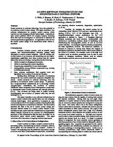
2. Automation Agents for Manufacturing Control Extending the concept of the automation component, defined by Sünder et al. [13], we define the concept of an automation agent as a basic element of a distributed intelligent control system. Such a system is controlled in a decentralized manner with multiple automation agents cooperating to accomplish complex tasks. Additionally, a certain reconfiguration and fault-tolerance capability shall be provided by each automation agent at its own level. 2.1. Architecture of an Automation Agent In the manufacturing domain, a component incorporating hardware (sensors and actuators) as well as control software is typically referred to as a mechatronic component. The application of agent technology to such a component and the separation of the control software into a HLC and a LLC, delivers the structure of an automation agent (see Figure 1). This separation into two layers is appropriate due to the different requirements that need to be taken into account. While the physical component represents the embodiment of the automation agent, the software parts serve as its “artificial” intelligence controlling the physical component to achieve the automation agent’s goals. The upper HLC layer has responsibilities that encompass organizational and supervisory functions. It plans and schedules the automation agent’s activities, coordinates its actions with other subsystems/agents in the environment and sets related requirements to the subjacent LLC layer with the aim to achieve its own and the system’s goals [14]. The HLC is not required to perform real-time tasks as computation times and interactions with other agents or human operators might take a longer time. The LLC, which is built on top of the physical component, is responsible for managing the underlined physical system, whose reaction time requires real-time response. It comprises a limited set of reactive behaviors to directly control the physical component, collects and processes the information from sensors and based on the
Figure 1. Structure of an automation agent. result performs particular actions or informs the HLC about significant events. The LLC informs the HLC about the accomplishment of delegated tasks, but can also diagnose certain types of failures (e.g. a conveyor stock) and informs the upper layer about it. Communication between the two layers is performed by using a defined interface, as for instance shown in [15, 21]. 2.2. Integration of the Automation Agent As mentioned before, the heterogeneous nature of the manufacturing domain needs to be taken into account in order to meet the requirement of reusability of agent technology. Therefore our approach comprises a HLC that is applicable for different types of LLC. Figure 2 shows the concept of automation agents with different types of LLCs connectable to their HLC. Therefore we require an interface that supports the communication between the HLC and different LLCs. We define the notion of a generic interface because vital parts of this interface shall follow the principle of generality in order to easily extend the range of supported LLCs. Obviously the lower level elements of the interface that are in direct contact with the LLC need to be customized corresponding to the supported LLC likewise to a software driver. Our approach shall not only be applicable for real systems but also for simulation, as this is an effective
Figure 2. Concept for integrating automation agents with different LLC types.
way for testing scenarios and improving the quality of the solutions. Furthermore the number of implemented multi-agent control systems is yet small and therefore simulation is a cheap method to demonstrate their potential [15, 16]. In order to present the functionality of our approach we present three use-cases of control software environments that base on diverse control paradigms. One of these control software environments, which is described in the following section, is based on the standard IEC 61499 which is focused on in academic research but not yet widely applied in the industry. The other two are based on the industrially accepted standard IEC 61131. It is of vital importance for agent technologies to be usable in conjunction with industrially applied technologies to prove their feasibility and show their benefits within the manufacturing domain.
3. Use-case of a Distributed Automation Environment based on IEC 61499 The standard IEC 61499 is a relatively new standard that defines a generic architecture and guidelines for applying function blocks in distributed Industrial Process Measurement and Control Systems (IPMCSs). Thereby it extends the models and programming languages of the standard IEC 61131 towards distribution. Related to the work presented in this paper, especially Part 1 is of relevance as it describes the general architecture and models of IEC 61499. This standard offers some advantages for its application as basic control software for lower level industrial control. Firstly, it is based on the industrially widely employed standard IEC 61131 which supports an easier adoption of this technology. Secondly, it offers features such as modularity as well as support for distribution by incorporating an event-triggered execution model. As a multi-agent system can employ numerous agents for controlling the system’s physical components, the support for distribution makes IEC 61499 a suitable technology for creating the LLC of such a system. Moreover the event-triggered execution model allows immediate reactions in the case of a detected failure. Figure 3 shows the system architecture with an LLC based on IEC 61499. The HLC performs the reasoning tasks while the LLC is responsible for the reactive behavior of each component as well as the actual control of its physical parts such as sensors and actuators. The LLC layer contains a network of IEC 61499 function blocks representing the application and requires an IEC 61499 runtime environment to run it on the Controller. Communication channels are used for encapsulating the transmission paths between HLC and LLC. These can be either upstream, downstream or bidirectional, depending on the required communication direction.
Figure 3. System architecture with an LLC based on IEC 61499. Several implementation variants are possible such as the use of shared memory [17], if HLC and LLC reside on the same controller, or a network-based solution [15, 18], which offers more flexibility concerning the actual execution location of each layer. The interface between HLC and LLC is designed according to a “separation of concerns” as follows: Channel: The used channel needs to be known by the involved participants as both partners must use the same means for communication. Message: Communication is realized in an asynchronous message-based manner, which is supported by the event-triggered execution model of IEC 61499. Message Content: Transmitted data needs to be understandable for all communication partners and interpreted in the same way. The implementation of this interface is realized on the LLC side with IEC 61499 service interface function blocks (SIFBs) that cover all aspects of the communication. These different aspects are provided as particular entities within an ontology on the HLC side to allow reasoning on the received data. In order to test the behavior of the multi-agent system, a simulation of the target system is used that integrates the physical characteristics of all components. Each component is represented by a function block which emulates the component’s behavior and offers an interface providing virtual inputs and outputs, which would be the controller’s physical I/Os in the case of the real system, to be accessed by the LLC. For example, a simulated diverter offers three sensor values that indicate the location of pallets as virtual inputs and one blocker and the actual switch as virtual outputs to the LLC. Also certain parameters are specified for each component instance, such as the length of a specific conveyor. The applied visualization system is based on IEC 61499 function blocks as well. Holobloc’s FBDK [19], which was used for the development of the IEC 61499 LLC, provides function blocks for the design of a
graphical user interface (GUI). However, in order to realize a detailed graphical representation of the system, which additionally can be displayed on a remote device, function blocks were developed that make use of Java Swing and the Abstract Window Toolkit (AWT). Thereby a first library with certain reusable HMI modules for components such as conveyor and diverter was created. The presented approach is implemented in [3] as a part of the Knowledge-based Multi-Agent System Architecture (KASA). It enables ontology-based communication and cooperation among a set of autonomous and heterogeneous units/agents, and has been applied in the assembly domain. The “Testbed for Distributed Holonic Control” at the Institute for Automation and Control, Vienna University of Technology, has been used as a basis for the simulation of the developed architecture [20].
4. Use-case of a Manufacturing Agent Simulation Tool based IEC 61131: MAST The Manufacturing Agent Simulation Tool (MAST) is a typical example of the multi-agent manufacturing control system that features both high-level control (HLC) and low-level control (LLC) functionality. The HLC is provided by Java agents representing various material handling components like a conveyor belt, diverter, workcell, sensor, etc. The LLC is based on the IEC 61131 standard of languages for programmable logic controllers (PLC), particularly ladder logic and structured text. The reason for integrating the agents with classical scan-based, real-time control executed on PLC is to simplify the proliferation of this new multiagent technology into the industrial automation domain, where PLCs, operator panels and SCADA systems are still predominantly used. The overall architecture of MAST system is depicted in Figure 4. The system applies a Tag-based interface as a communication channel between HLC, LLC and the simulation subsystem. This interface is designed in consistency with a way how current PLC programs and visualization tools interact with the controlled manufacturing environment. Basically, sensors and actuators placed in the physical environment are interconnected by an industrial network (like DeviceNet) to the I/O cards plugged into the PLC. The respective I/O values are transferred to the PLC memory, where they are stored in variables called tags. The low-level IEC 61131 control programs process these tags in a scan-based manner, i.e., periodically read the input values, perform the computational logic (using also tags to store the temporary values) and set the output values, which are then transferred via industrial network back to the actuators. So, reading and writing of the tags is the basic functionality of the LLC. It is also the case of
Figure 4. MAST system architecture from the HLC communication point of view. SCADA and HMI tools that use the actual tag values for visualization and basic user interaction with the controlled process. The Tag-based interface applied in the MAST system architecture is used to transfer the tag values between the PLC memory and the HLC. It is also used by the simulation engine that emulates the function and behavior of the physical system. In this case, the PLC is fed by emulated I/Os instead of being connected to the real physical process [21]. The visualization subsystem of MAST, which is in fact merged with the simulation subsystem, also uses the Tag-based interface to display the status of the controlled process in a GUI. Technically, the Tag-based interface is implemented as a Java/C++ API that allows Java or C++ programs running on a remote PC to read and write the tag values from the LogixTM controllers. It also supports a subscribe-notify mechanism for automatic notification of the tag value change. The primary focus area of the MAST system are the material handling tasks, i.e., the transportation of products and materials among machines via a redundant network of conveyors. The library of agent classes includes basic types of components like conveyor belt, diverter, docking station, etc. The essential characteristic is the cooperation of agents on various tasks, mainly routing of products through the conveyor network and dynamic reconfiguration of routing paths in case of machine break downs or modifications to the physical layout of the factory. A pilot real deployment of MAST has been carried out in the Odo Struger Laboratory at the TU Vienna’s ACIN institute [21]. Firstly, the simulation of the lab’s transportation system was built and functionality of the agents verified. Secondly, the tagbased interface was configured to access the real I/O values held in the ControlLogix controller. Thus, the agent control system has been used without any change to control the real-world manufacturing set-up.
5. Use-case of Commercially Available Software based on IEC 61131: zenon & straton zenon is a software package for industrial automation by the HMI/SCADA developer COPA-DATA [22]. It is used by many companies for process visualization, machine operation (HMI) and as a control system (SCADA). zenon offers simple object-oriented engineering, full compatibility from the terminal to the control room and a high level of security. zenon can be applied on industrial PCs as well as on any other hardware running WindowsTM CE. Companies in many different industries, such as machinery construction, automotive, pharmaceutical, food and beverage, chemical engineering or energy supply, employ zenon. zenon provides several hundred communication protocols in order to communicate with other parts of the automation environment. This could be PLCs or other control systems (e.g. ERP programs). As Hard-PLC/Soft-PLC/bus terminal controller, straton allows for the quick and secure engineering of industrial systems. It is based completely on IEC 611313 and works with all current WindowsTM operating systems. The programming interface supports all five languages defined in IEC 61131 as well as all current field bus systems. Because of the full integration of its development environment in the SCADA system zenon, the users can profit from simple variable handling, consistent support of complex data types and objectoriented engineering. straton as a pure IEC 61131 programming system and portable runtime can only act as a LLC in the work described in this paper. It therefore requires an interface to the HLC (see Figure 5). Simulation can be realized on straton as well and the communication established tag based via an own proprietary protocol likewise to the communication used by MAST (see Section 4). straton is basically designed to read inputs and calculate the outputs cyclically. The input values are gathered from sensors. The output values are used to control actuators. The cyclic calculation of the outputs referring to the inputs can be done up to 10000 times a second. straton reads and writes the I/O data basically through field bus systems (e.g. Profibus, Modbus). The standard runtime system is designed for Windows based platforms. However straton can be ported to other operating systems like VxWorks, Linux, DOS, etc. The communication to the HMI/SCADA system zenon is done via a fast TCP/IP based protocol. zenon can either show the value of the tags representing the I/Os or show the values of calculated tags. Furthermore zenon as a SCADA system has several possibilities to archive and trend the values of the tags. straton was yet never utilized in conjunction with agent technology but is proven in several real life
Figure 5. COPA-DATA system architecture with required HLC and HLC-LLC interface. applications. Therefore its employment as a LLC can show the feasibility of agent based systems in an industrial domain. Furthermore, with zenon also the visualization of the system can be realized by employing a commercial tool.
6. The Generic HLC-LLC Interface As shown in Figure 6, our approach shall provide the possibility to integrate at first three different types of LLC. However, it also shall allow an easy extension for other LLC types as well. An interface is therefore required that connects the two layers HLC and LLC taking into account the different software paradigms that are actually applied on these layers. Commands and requests need to be sent from the HLC to the LLC and reports and failure notifications from the LLC to the HLC. Hence, the purpose of the generic HLC-LLC interface is to make the functionalities from the LLC accessible to the HLC in a uniform way. This raises several challenges: Communication protocols are heterogeneous. The different types of LLC use different communication protocols (e.g., data table tags, channels) which have different properties
Figure 6. Concept for the integration of the different LLC types.
(synchronous vs. asynchronous interaction, messages vs. tags, event-driven vs. cycle-based, etc.). Definitions of commands are heterogeneous. Even when controlling the same kind of physical component, there are differences in the way a command is defined. To address these challenges we propose a generic interface consisting of: A high-level language for expressing semantic descriptions of commands to the LLC. This language enables the HLC to express commands using the essential concepts of the domain, without having to know precisely how the invocation of the LLC is performed. An architecture for (i) interpreting commands expressed using the high-level language and translating it into low-level commands, specific to each LLC flavor, (ii) interacting with various kinds of LLC in an asynchronous, event-driven way. Figure 7 illustrates the principles of the generic interface. We use the example of a stopper, which can block workpieces on a conveyor-based transportation system. In the following, we consider a stopper named stopper_01 operating at the place P1, which uses an IEC 61131 LLC, and a stopper named stopper_02 operating at place P2, which uses an IEC 61499 LLC. The upper part of Figure 7 illustrates a command sent by the HLC to the LLC, which is expressed using the high-level description language. The lower part illustrates how the command is finally transmitted to the LLC, i.e. by writing a tag named “st_01” with a value “1” in case of an IEC 61131 LLC or sending a message with content “01” to the channel “239.191.0.14:61100” in case of an IEC 61499 LLC. The center of the picture illustrates the generic interface. It is composed of two parts: a generic interpreter and a set of specific adapters. The generic interpreter receives the command from the HLC and is capable of analyzing it and transferring it to a relevant adapter. Each adapter can interpret the command in order to translate it into a direct command to the LLC. Both elements rely on a semantic description of the LLC functionality, which describes the relation between the high-level concepts used in the command from the HLC and the LLC invocation. Figure 7 represents a specific adapter for IEC 61131 (tag-based) and a specific adapter for IEC 61499 (channel-based). The semantic description of the LLC functionality plays an essential role in the generic interface. It gives the necessary information for translating the high-level command into a low-level command. Figure 8 illustrates a description of the functionality of stopper_01, based on IEC 61131. Figure 9 gives a similar illustration for the functionality of stopper_02 based on IEC 61499. In this description, the functionality provided by a stopper is composed of two services. The first one, named
Automation Agent Stopper_01 HLC
Automation Agent Stopper_02 HLC
Send command "REQUEST Action :type #BlockWorkpieceAtP1" Generic Interface
Generic Interpreter uses
IEC 61131 Adapter
Semantic Description of LLC functionality
Write tag "stopper_01" with value "1"
Send command "REQUEST Action :type #BlockWorkpieceAtP2" Generic Interface
Generic Interpreter uses
IEC 61499 Adapter
Semantic Description of LLC functionality
Send message "01" on channel 239.191.0.14:61100
LLC (IEC 61131)
LLC (IEC 61499)
Physical Stopper 01
Physical Stopper 02
Figure 7. Principles of the generic HLCLLC interface. Service id = activate type = #BlockWorkpieceAtP1 grounding = LogixTagGrounding(write, st_01,1) Service id = deactivate type = #ReleaseWorkpieceAtP1 grounding = LogixTagGrounding(write, st_01,0)
Figure 8. Description of stopper_01 functionality based on IEC 61131.
Figure 9. Description of stopper_02 functionality based on IEC 61499. “activate” enables the HLC to activate the stopper, thus blocking all incoming pallets. The second one, named “deactivate” enables the HLC to deactivate the stopper, thus releasing all incoming pallets. Each service is described using three elements: id gives an identifier for the service, type defines the type of service and grounding defines how to invoke the LLC for providing the service. We can note that the description of each service merges the high-level description (expressed by the type of the service) and the low-level description (expressed by the grounding of the service). The type is defined using the Web Ontology Language (OWL [23]). Using OWL, it is possible to express ontologies based on description logics, with a formal specification of concepts and automatic classification. Figure 10 illustrates a part of the classification of service types for our example. This classification is organized in several levels:
The top level is about generic concepts, which are common to all kind of automation agents (e.g., Event, Action). The second level is about concepts specific to a type of physical component. For the stopper example, we define that blocking a workpiece and releasing a workpiece are a kind of actions (that a stopper can do). The third level is about concepts specific to a given physical component. For the stopper example, we define a concept #BlockWorkpieceAtP1, indicating that blocking a workpiece at a place P1 (where the stopper operates) is a specific action (that only stopper_01 can do). This concept is defined by restricting the concepts of blocking a workpiece only to a specific place, P1. Similarly, we define a concept #BlockWorkpieceAtP2, for stopper_02. Using the type description, the generic interpreter matches the command requested by the HLC with the actual services provided by the LLC functionality. From the description, it can then decide which adapter to use for actually sending the command to the LLC. In our example, in case of a request to activate the stopper_01, it should use the “activate” service with a LogixTagGrounding, so the IEC 61131 adapter should be used. In case of stopper_02, the IEC 61499 adapter with ChannelGrounding would be used. When an adapter receives the command expressed in the high-level language, it performs two steps: The adapter translates the command into a direct LLC command. To do so, it uses the information contained in the description of the functionality. In our example, the translation is direct, as the command for activating the stopper does not require any parameter. In more complex cases, the adapter would have to interpret more precisely the type of the functionality to define parameters for the command. The adapter sends the command to the LLC, using the relevant communication protocol. In the example of stopper_01, it means that the adapter writes the tag named “st_01” with the value “1”.
Figure 10. Partial classification of service types.
In case of stopper_02, the IEC 61499 adapter is used to send a message with content “01” to the channel “239.191.0.14:61100”. In addition to the simple case of commanding an action illustrated by our example, the generic HLC-LLC interface also allows the HLC to subscribe and be notified of changes at the LLC level. In that case, the HLC sends a subscription command, which is translated by a relevant adapter in a similar manner. Then, whenever a relevant change happens at the LLC level, the adapter informs the HLC by sending a message expressed using the high-level language. Integrating a given type of LLC with the generic HLC-LLC interface is done in two steps: (i) definition of the grounding language for the considered LLC and (ii) implementation of the adapter to the LLC. As described above, we have mainly been considering adapters for two types of LLC. For a LLC based on IEC 61131 (e.g., as used in the MAST and COPA-DATA solutions), the grounding language enables the description of read and write operations of a particular tag value. The language thus contains formulas of the type: LogixTagGrounding(, , ) Additionally, the notification of changes requires the adapter to monitor changes of tag values. This is provided by the existing subscribe-notify mechanism provided by the Tag-based interface used in MAST (see section 4), which serves as a bridge between the adapter and a LLC based on IEC 61131. For a LLC based on IEC 61499, the grounding language enables the expression of operations for sending and receiving messages with a given content on a given channel. The language thus contains formulas of the type: ChannelGrounding(, , ) For notification of changes, the adapter only needs to listen for messages on the relevant channel, since IEC 61499 provides the appropriate notification mechanisms.
7. Conclusion and Outlook The complexity of the manufacturing environment is especially reflected through the heterogeneous nature of applied control systems. The multi-agent paradigm is seen as a promising way to improve the effectiveness and efficiency of manufacturing systems. In this paper we presented an agent-based approach that enables the integration of diverse control software with and within such an environment. With three use cases in mind, we show the ability of our concept to support the principles of generality and reusability as well as the ability to be extended and backed up with related simulation. Our generic HLC-LLC interface is a vital part for the integration of different LLC types within one multiagent system. The presented approach and first
implementation examples are promising for solving this communication challenge. However, also communication means are required that enable the direct exchange of data between different types of LLC of two or more automation agents. Object Linking and Embedding (OLE) for Process Control – OPC – defines the communication between control devices from different vendors. Its application may therefore represent a possible solution for realizing data exchanges between the different types of LLC. But also other solutions, for instance with a local preprocessing of data for translation, may support the communication between LLC devices that employ different paradigms of control software.
[10]
[11]
[12]
[13]
Acknoledgement [14]
The authors acknowledge the financial support from the FIT-IT: Semantic Systems program, an initiative of the Austrian federal ministry of transport, innovation and technology (bm:vit) under contract FFG 815132.
[15]
References [1]
[2] [3]
[4]
[5]
[6]
[7]
[8]
[9]
N. Jennings and S. Bussmann, “Agent-based control systems: Why are they suited to engineering complex systems?” IEEE Control Systems Magazine, Vol. 23, pp. 61-73, 2003. K. P. Sycara, “Multiagent systems,” AI MAGAZINE, Vol. 19, pp. 79-92, 1998. M. Merdan, Knowledge-based Multi-Agent Architecture Applied in the Assembly Domain, PhD Thesis, Vienna University of Technology, 2009. M. Pěchouček, and V. Mařík, “Industrial deployment of multi-agent technologies: review and selected case studies,” Autonomous Agents and Multi-Agent Systems, Vol. 17, pp. 397-431, 2008. P. Valckenaers, “Challenges of Next Generation Manufacturing Systems,” Integration of Software Specification Techniques for Applications in Engineering, pp. 23-28, 2004. R. Brennan, and W. O, “A simulation test-bed to evaluate multi-agent control of manufacturing systems,” Proceedings of the 32nd conference on Winter Simulation, Vol. 2, pp. 1747-1756, 2000. J. L. M. Lastra, E. L. Torres, and A. W. Colombo, “A 3D Visualization and Simulation Framework for Intelligent Physical Agents,” Holonic and Multi-Agent Systems for Manufacturing, pp. 23-38, 2005. S. Bussmann, and K. Schild, “An agent-based approach to the control of flexible production systems,” Proceedings of the 8th IEEE International Conference on Emergent Technologies and Factory Automation (ETFA’01), pp. 481-488, 2001. F. P. Maturana, P. Tichý, P. Šlechta, F. Discenzo, R. J. Staron, and K. Hall, “Distributed multi-agent
[16]
[17]
[18]
[19] [20]
[21]
[22] [23]
architecture for automation systems,” Expert Systems with Applications, Vol. 26, pp. 49-56, 2004. IEC TC65, IEC 61131: Programmable Controllers – Part 3: Programming languages, International Electrotechnical Commission (IEC), 1993. IEC TC65, IEC 61499: Function blocks for industrialprocess measurement and control systems – Parts 1 to 4, International Electrotechnical Commission (IEC), 20042005. V. Vyatkin, Z. Salcic, P. Roop, and J. Fitzgerald, “Now That’s Smart!” IEEE Industrial Electronics Magazine, Vol. 1, Iss. 4, pp. 17-29, 2007. C. Sünder, A. Zoitl, and C. Dutzler, “Functional structure-based modelling of automation systems,” International Journal of Manufacturing Research, Vol. 1, Iss. 4, pp. 405-420, 2006. J. H. Christensen, “HMS/FB architecture and its implementation,” Agent-Based Manufacturing: Advances in the Holonic Approach, pp. 53-87, Springer Verlag, Berlin/Heidelberg, Germany, 2003. M. Merdan, W. Lepuschitz, I. Hegny, and G. Koppensteiner, “Application of a Communication Interface between Agents and the Low Level Control,” Proceedings of the 4th International Conference on Autonomous Robots and Agents (ICARA’09), pp. 628633, 2009. P. Vrba, and V. Mařik, “Simulation in Agent-based Manufacturing Control Systems,” Proceedings of the IEEE International Conference on Systems, Men and Cybernetics, pp. 1718-1723, 2005. O. J. Lopez, and J. M. Lastra, “A Real-Time Interface for Agent-Based Control,” IEEE 2nd International Symposium on Industrial Embedded Systems (SIES’07), pp. 49-54, 2007. I. Hegny, O. Hummer-Koppendorfer, A. Zoitl, G. Koppensteiner, and M. Merdan, “Integrating Software Agents and IEC 61499 Realtime Control for Reconfigurable Distributed Manufacturing Systems,” IEEE 3rd International Symposium on Industrial Embedded Systems (SIES’08), pp. 249-252, 2008. Holobloc, FBDK – Function Block Development Kit. http://www.holobloc.com, last visited April 2009. M. Merdan, G. Koppensteiner, I. Hegny, and B. FavreBulle, “Application of an ontology in a transport domain,” IEEE International Conference on Industrial Technology (ICIT’08), pp. 1-6, 2008. P. Vrba, V. Mařík, and M. Merdan, “Physical Deployment of Agent-based Industrial Control Solutions: MAST Story,” Proceedings of IEEE International Conference on Distributed HumanMachine Systems, pp. 133-139, 2008. COPA-DATA Website: http://www.copadata.at, last visited April 2009. M. Dean, and G. Schreiber, OWL Web Ontology Language reference, 2004. Available at: http://www.w3.org/TR/owl-ref/, last visited April 2009.