Integration of Design Tools and Semantic Interoperability Gabor Karsai Jeff Gray Institute for Software-Integrated Systems Vanderbilt University PO Box 1829 Station B Nashville, TN 37235,USA {gabor,jgray}@vuse.vanderbilt.edu George Bloor Phantom Works The Boeing Company
[email protected]
Abstract The integration of software tools used in an engineering process is a problem that arises frequently in large-scale projects. Simple solutions for integration are insufficient in the case of complex engineering tools and processes. The integration solution must also account for the evolution of the system, as tools and processes change over time. This paper shows a new approach to the problem, describes the supporting infrastructure, and discusses the background model-integrated generation technology.
Introduction Every large-scale project on computer-based systems that uses software-based engineering tools has to face the problem of their integration. Each of these tools is usually a highly specialized package that contributes to a crucial step in the engineering process. While tool vendors may offer tool suites, the tools used in practice are very rarely integrated across the engineering process. In many cases, the tools were simply not designed with easy integration in mind. Current systems engineering tools tend to be built as isolated “stovepipe” solutions. They must inter-operate, but often the integration happens by chance, in a very human labor-intensive way, leaving users frustrated. The traditional solution of proposing the “next -generation systems engineering tool” that does everything that current individual tools do, and will be “on-line in a year from now,” does not help in alleviating the problems. Instead, we need to look for an integration of these tools —as they are— into a coherent framework, which ensures semantic interoperability among the component systems along with a strategy and toolset that supports this process.
Solving the integration problem is not easy. The diversity of tools, the variations in their method of user interactions, and differences in file formats make the task formidable. However, the potential benefits are also great: using information captured in one tool in the context of another tool saves valuable, but often uninteresting, effort. In this paper a solution is shown which approaches the integration issue from a model-based viewpoint. Modelintegrated computing [7] relies on the interpretation and use of domain-specific models in run-time environments. The domain models capture the relevant entities and their relationships in a specific domain, and are used in a generation process to create executable systems. One, often used example of MIC is that of the signal processing domain: models capture signal processing architectures in the form of signal flow diagrams, which are then compiled into an executable system that implements the specification. MIC has been successfully applied in the development of various computer-based systems, including aerospace, manufacturing industry, and testing applications. This paper shows how the MIC technology can be applied in the integration problem discussed above. The trick is to represent (i.e., ‘model’) the semantics and the behavior of the individual tools and the transformations among them, and then generate software components that solve the integration problem. The approach has been used to solve the integration of a number of tools. Experience indicates that the techniques are feasible for large-scale integration as well.
141
Background The development of computer-based systems typically involves a large number of engineering tools addressing a wide range of domains. One should recognize that Computer Based Systems are not simply software systems, but rather computing systems (software and hardware) that are tightly coupled to their respective environments. This necessitates the use of various engineering tools that model and analyze all aspects of the system, including the computing system and the physical environment. The trouble is, the tools are specialized for particular domains and tasks in those domains, and they very rarely communicate with each other (unless they form a toolsuite, typically implemented by a single vendor). Whenever the tool integration issue comes up, organizations tend to generate quick solutions that eventually turn out to be insufficient. Some of these nonsolutions are reviewed below.
File Translators The first “solution” that comes to mind is to argue for using “file translators” that translate between the file formats of the different tools. File translators are specialized programs which do nothing more than read data generated by one tool (typically the physical data file) and convert its contents into another data file suitable for consumption by another tool. Unfortunately, this approach has very some serious drawbacks. The translator writer has to be extremely proficient both in the file formats of the individual tools, and in the semantics of those tools, to be able to write the translator. The translator writing is a very time-consuming process: it requires special skills and intricate knowledge of the tools to be successful. Arguably the biggest shortcoming of the approach is its inherent problem with scalability. It is trivial to show that the number of translators required to integrate n tools is proportional to the square of the number of tools. To put it in another form: whenever a new tool is added to the suite, the same number of translators has to be prepared as the number of tools already in the package. This argument assumes the need for full tool interoperability, of course.
Middleware: CORBA, COM One can consider the tools to be integrated as software components. There are well-established standards and tools for software component integration: CORBA[2] and COM[1] being the two major examples. It seems obvious that a middleware package can be used to solve the integration problem easily. Unfortunately, this solution als o has its problems. Object-oriented middleware systems rely on the “remote object method invocation” approach. That is, they provide support for making method invocations on objects hosted on various nodes of a network. The theory is that one can
create a “wrapper” object around tools, and in some way these tools will communicate with each other through remote method calls. Now to design and implement the communication between two tools can be very complicated, and it can quickly become a nightmare for a large number of tools. The point is that the middleware provides relatively low-level facilities for tool interactions, and all higher-level functions should be built from scratch. Some sort of translation needs to be done as well that requires deep understanding of tool behavior and data structures. Furthermore, if the tool cannot simply be “wrapped” as an object, one has to revert to the file manipulation techniques mentioned above, with all its shortcomings.
Universal language This solution uses a radically different strategy from the above, although it requires the support of at least one of the above techniques. One can think about the tool integration problem in the context of the particular engineering process where it is needed. Processes (and organizations) tend to have their own vocabulary and idioms. So the idea comes: why not design a universal “language” (a database schema, in practice) that will be used by all the tools, across the process. Once a language is defined, we just have to write translators for each tool, or setup the middleware communications to use this shared language. This is a more efficient solution because the number of translators increases linearly by the number of tools. Unfortunately, where the approach breaks down is in the practical difficulty of coming up with this universal language. Projects tools are often selected using a opportunistic approach, and it is very difficult to make changes to the “universal” language during the lifetime of the project. It seems that the “universal” language is not very “universal” at all because it can’t be used on another project.
Lessons Learned Integration of systems (into a system of systems) is traditionally one of the most expensive and difficult tasks in the engineering of software systems. The situation is only made worse by the lack of systematic approaches. While component integration technologies, like CORBA, DCOM, etc., solve part of the problem, they do not give much help in integrating two sophisticated applications (i.e. systems), let alone a large number of them. Higherlevel, semantically aware software tools are needed that help in building integration solutions, with minimum impact on existing systems, capitalizing on existing investment. Specifically, there are a couple of important points one learns from the above discussion.
•
142
Attention should be paid to the effort required to integrate a new tool. An integration solution does not
• •
work if the integration costs more than having people manually translate the data. Scalability is an issue. If adding a single new tool requires the writing of a number of new software packages, then the approach is clearly a failure.
the union nor the intersection of the data models of the individual tools, because tool data models will overlap (although not completely). The integrated data model (IDM) is the vehicle that implements the shared semantics across the t ools.
One needs a very deep understanding of the tool semantics before attempting any kind of integration. How fast this understanding can be turned into an integration solution will determine the success of any kind integration paradigm. Next an approach is described the addresses these issues and offers a solution to the problem.
LRU MM
LRU
VAR
FR FDE
MSG
The approach
UNIT OBS
The techniques described above clearly indicate that a tool integration solution should address the issue of semantic interoperability. We want our tools to work together towards a goal, and in order to do that, some mutual understanding or, shared semantics is needed. The tool integration solution should be the implementation vehicle for this shared semantics.
LRU MM FR
LRU
VAR
FDE
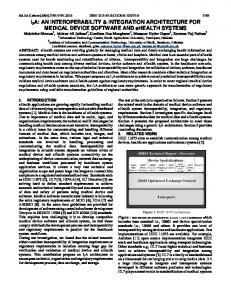
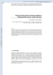
Figure 1: Tool integration If one associates semantics with static semantics (in the UML-sense [3]), the tool integration problem can be visualized as shown on Figure 1. Static semantics can be described as the integration of a data model that captures the allowed entities and relationships in the tool’s data with further logical constraints (Boolean invariants that must be true on the data). If we have a tool X with a data model, we want to take this data and map it into the data model of another tool Y. If we restrict the data model used to the “entity-relationship-attribute” variety [3], tool integration means the solving the mapping problem between two database schemas. Unfortunately, if we have more than two tools, the mapping problem becomes complicated, and we get to the same scaling problem as that we have seen with the file translators. It is more feasible to establish an integrated data model first, and then map the data model of each tool into that as shown on Figure 2. The integrated data model can be defined as a data model that is rich enough to contain data from any of the tools. Note that this integrated data model is neither
ALR
Figure 2: Tool Integration with Integrated Data Model The Architecture The approach presented here is architecture-based, shown on Figure 3. The architecture contains two kinds of major components: the Integrated Model Server (IMS), and the Tool Adaptors (TA). The communication mechanism between the major components is implemented in CORBA (although any middleware package is suitable here). The functions of the components are as follows. The IMS is responsible for providing semantic translation services for the constituent tools. By semantic translation we mean a transformation of data from one data model into another one while preserving the semantics of the input data model and enforcing the semantics of the output data model. Again, semantics is understood here as static semantics, expressed in the form of constraints on the data. The IMS also provides a short-term repository for storing the result of the translation. The schema used in the repository is that of the Integrated Data Model.
SEMANTIC Mapping
Semantic Translator for Tool-X
INTEGRATED MODEL DATABASE
Integrated Model Server CMI Protocol (CORBA/COM) Tool Adaptor for Tool--X Tool
SYNTACTIC Mapping
Figure 3: Tool Integration Architecture
143
The TA-s are responsible for interfacing with the tool directly. Their goal is to read and write tool data, directly in the form the tool generates and expects it. The adaptors ship the data read to the IMS and receive data from IMS that they send to the tool. The TA accesses the tool’s data in whatever way it is possible and suitable: through a data file, a COM interface, or something else. Note that the TA performs a syntactic translation on the data from the native data format of the tool to that of the middleware datastructures. In a general sense the architecture operates as follows. When a tool wants to make its data available for other tools, its TA is started. The TA fetches the data from the tool and converts it into the “network” format and ships it to the IMS. The IMS receives it, performs a semantic translation on it, and places the result into its repository. At this point the data is transformed into an IDM-compliant form. When another tool wants use the data just translated, it accesses the IMS. The IMS performs a semantic translation on the data from the IDM-compliant data model into the tool-specific data model, and ships the result to the tool’s TA. The TA will take the data in network form and convert it into the physical data format of the tool. Note that the architecture separates the concerns of syntax and semantics, and assigns them to two different components: the IMS and the TA-s. This distinction makes the development of the integration solution easier. The binding between the major components is the middleware, specifically a protocol for data interchange.
The Common Model Interface Protocol The Common Model Interface (CMI) protocol defines the rules of communication and the form of the data-structures used in the interactions between the IMS and the TA-s. The CMI is the same across all the tools: this is the common, canonical “form” into which all tool adaptors translate their data. The protocol has many components related to data transfer and interaction with the IMS, but only the most significant aspects will discussed here. Note that the protocol is defined in the form of a CORBA IDL specification, and as such it relies on the remote method invocation capabilities provided by CORBA. In the architecture, the objects on which the methods are executed always reside in the IMS. The primary purpose of the protocol is to facilitate data transfer between the TA-s and the IMS. The core data model used in CMI is a variant of the traditional entityrelationship-attribute data model. Data consists of attributed objects, which can be models, entities, and relations. An attribute is simply a key-value pair (the data type of values must be from a small, but powerful set of primitive data types, and arrays of primitive values are allowed). An entity is a simple attributed object, without any further structure. A relationship is an attributed object that has two collections of objects, called roles, associated
with it: these collections contain entities or models that play those roles in the relation. A model is an attributed object that contains entities, relations, and other models. This simple data model is sufficient to express data coming from any tool, but because of the differences among the tools it is not sufficient for precise differentiation among the tools. Therefore, each data object is tagged with a type tag that indicates the meaning of the object. The CMI makes this distinction between the data and its type apparent by dealing with the data on two-levels. Meta-data describes the data model of a particular tool. Physically, meta-data contains models, entities, and relations, but these are meta-models, meta-entities and meta-relations that describe the tool’s data model. The IMS exposes the meta-data of each of the tools as CORBA objects. Thus, each tool – or a generic browser – can access the meta-data for each of the tools. The instancedata is data to be transferred. The instance-data contains models, entities and relations, where each data object is tagged with the corresponding meta-data object’s id (technically an object reference). This tagging makes it possible for the IMS to figure out what the “real” type of a data object is. Also, this makes it possible for a TA to get the same information. Thus, the TA should access the data model of its tool available as meta-data objects in the IMS. Whenever data is shipped to the IMS, the (instance) data objects should be tagged with the meta-data references. Whenever instance data is received, it will be tagged with the same meta-data references, and the TA can parse and process the packet accordingly. The remaining parts of the CMI deal with the specific interactions with the IMS. These interactions are expressed in the form of object interfaces. Some of the capabilities are listed below: • Directory services. These interfaces define access to the contents of the IMS repository, which is organized like a directory hierarchy. • Session management. This interface implements the operations for fetching and storing data, removing objects, etc. • IMS access. This interface implements the login/logout capabilities, and some other global operations (e.g. retrieval of IMS clock data).
The Evolution of the System The architecture discussed above only gives the framework for implementing an integration solution: it does not speak about how the system evolves. When implementing an integration solution one has to recognize that the solution will never stay constant: new tools will be added, tool data models will introduced, and, perhaps tools will be removed. This continuous change necessitates the designer to place emphasis on how the system will evolve over time.
144
During the evolution of the system, the most frequent problem is the addition of new tools. This means, a new tool adaptor has to be developed, and the IMS should be upgraded to “understand” the new tool. The upgrade means changes in the IDM (for the integrated model database), and the development of a new semantic translator that can manage the data of the new tool. Both of these are non-trivial steps, especially considering that we can already have a number of tools integrated in the system. The solution chosen here is closely related to the previous work on Model-Integrated Computing (MIC). In MIC, domain models are used to generate components that implement a system. In the integration framework, there are two kinds of models: 1. data models of the tools and that of the integrated data, and 2. translation (or mapping) models that capture how to transform data in one semantics into another semantics. If we somehow can capture and utilize these models in constructing an integration solution, then we can improve the evolutionary capabilities of the architecture. In the actual implementation the following has been done. IMS was developed not as a stand-alone, monolithic solution but rather as a “framework” that contains reusable components. Figure 4 shows the internals of a semantic translator in the IMS architecture. The reusable components contain the generic interfaces to the network side and to the repository side (accessible through the very same interface – just different implementations), the implementation of CMI services (directory, session and IMS access), and other housekeeping functions. To instantiate the IMS framework for a particular tool integration solution one has to build the semantic translators.
The semantic translators are not built by hand, rather, they are generated from models. Figure 5 shows how the semantic translators are structured and how they are generated. Each semantic translator has a set of static objects that represent the meta-data of the corresponding tool. The code for these objects is automatically generated from the data model of the tool. When the actual generation of the translator happens, the user must provide three models to the generator: the data model for the input, the data model for the output, and the translation model. (That is, each tool has two translators: one for translating into the IDM, and another one for translating from IDM.) The generator creates C++ code from the mapping specification which is then linked with the other generated code and the framework library elements to build up the IMS. Naturally the specification of the translation and mapping is key to the whole solution. One might think that the mapping is easy to formalize in the form of mapping rules of the form: map: (M,E,R,A) -> (M’,E’,R’,A’) where M,E,R, and A stand for models, entities, relations, and attributes, respectively. It is very easy to invent a simple mapping language that captures this, and it is simple to use and simple to generate code from it.
Tool Meta Model
CMI Impl
Model Model Instance Data
Tool Meta Data
INTEGRATED MODEL DATABASE
Constraint Enforcer
Figure 4: The Architecture of a Semantic Translator
Model Instance Data Data
UP Translator DOWN Translator Database
Interface
INTEGRATED MODEL DATABASE
Constraint Enforcer
Figure 5: Generation of a Semantic Translator
UP Translator Database DOWN Translator Database Interface
Meta Model of Integrated Models
Generator Generator
CMI Impl
Tool Meta Data
Mapping Model
However, after looking at the first domain data model of an actual application the mapping language idea was quickly abandoned. One problem with the data model was as follows. In one of the tools the surface data model was a simple object model, with a single level of containment. That is, models of type M contained entities of type E. In another tool the data model was hierarchical: models of type M’ contained entities of type E’ and models of type M’. At closer inspection, it turned out that the first tool’s data was really hierarchical: each entity contained an attribute (a string), whose value indicated the position of the entity in a hierarchy. That is, the attribute value was
145
used to encode a hierarchical relationship. This lead to the conclusion that the translation model needs the full power of a programming language in practical situations, and, while the mapping language is appealing, it is not sufficient. However, to write a translator without any help, from scratch can still be a daunting task. A practical engineering solution was chosen to help in this situation. Based on previous work on the specification of model interpreters [5], a language has been defined and the corresponding generator tool developed which supports the rapid construction of the translators. The approach is based on a variant of the Traversal/Visitor pattern [4][6]. The semantic translator traverses the input data structure, starting from a root point (which is always a model). As it performs the traversal (possibly in multiple passes), it executes “actions”. Actions can generate an output object, change an output object, etc. During the traversal process one can also pass along shared data structures, a kind of context, which is used to store state information with the traversal. The actual form of the specification contains two parts: the traversal specification and visitor specification. Traversal specifications give the answer to following question: “if we are at node of type X, where do we go next?” The “next” should be an object that is reachable from objects of type X. Visitor specifications capture what should be done when visiting a particular kind of object. There are two options: either take a “user action” (i.e. execute a piece of user-supplied code), or it can proceed with the traversal (i.e. call the traverser with the object being visited). These can be intermixed and/or omitted completely. Note that the specification has an outer, high-level language for describing the structure, while the inner parts are written in a procedural language, C++ in our case. The generator translates the above, mixed form specification into straight C++, building the code sequences for the traversal and iterative parts during the process. The resulting translator code then is linked with the rest of the IMS framework. We have found that writing translators using the traversal/visitor approach is very convenient, because the uninteresting parts (pointer tracking, iteration, selection next steps), are automatically taken care of by the generator. Another capability of the semantic translators is the handling of constraints. One can include Boolean expressions into the input of the generator that capture the static semantics of the data. From these expressions the generator creates C++ procedures that “evaluate” the expression in the context of the result of the translation (which is a data structure). This evaluation is a kind of post-processing, which verifies that the data is compliant with the constraints of the data model. In case of failure, an error is raised, and the translation cancelled. The objective of this constraint checking is to ensure that whatever data the tool receives from IMS is compliant with the semantic
rules implicitly enforced by the tool. On Figure 4, the box labeled “Constraint enforcer” represents this function. To summarize, the system evolution in the IMS is supported by the use of models (both data models and translation models) and the use of generators. Of course, when a new tool is added the integrated data model may have to be revised. Because the data model is also captured in the form of an explicit model, this usually does not cause problems. Experience shows that adding new things to the data model is trivial because the already existing translators do not have to be modified (assuming suitable defaults are used for the newly defined attributes). The evolution of the system with respect to the tool adaptors is also supported by a model-integrated approach. A tool adaptor framework has been defined that contains reusable components for building tool adaptors. The framework mostly deals with the CMI issues, because tool specific data formats are quite different and it is hard to come up with a generic solution. The tool data model is used to generate “glue-code” that lets the tool adaptor writer access CMI data structures using notions of the tool’s domain. That is, instead of referring to Models, one can refer to XYZModels, where XYZModel is a tool specific class. Thus, the process of upgrading an integration solution is as follows. 1. The data model of the tool to be integrated has to be determined. This data model should be expressed in the form suitable for processing by the generators. 2. The integrated data model needs to be updated (if at all) to be able to capture data from and for the new tool. 3. The tool adaptor has to be developed which reads and writes physical tool data. This requires the understanding the physical data layout, but does not require any semantic processing. 4. The semantic translator has to be modeled and generated. The modeling involves the description of the translation process in terms of traversal/visitor specifications. The above process was found quite manageable in practical situations. Note that the process does not deal with migrating the tool data. The assumption is that the tools “own” the data. The IMS contains only a short-term repository, whose contents can be discarded when a new upgrade is necessary. Because IMS merely provides translation and publication services, it was not designed as a process-database solution.
Experience, Conclusions and Future Work The approach described above has been used to develop integration solutions for various engineering tools. In one case, three tools have been integrated, in another case another four tools. For the latter case, the sizes of the
146
individual schemas and that of the integrated schema are shown in the table below.
Tool-1 Tool-2 Tool-3 Tool-4 Integrated
Model types [Attributes] 1[1] 1[1] 2[1,5] 2[1,3] 2[1,8]
Entity types [Attributes] 4[2,3,6,1] 2[7,19] 4[4,3,6,5] 2[4,2] 5[1,2,19,6,2]
Relation types 3 1 2 1 4
The main effort went into discovering the semantics of the tools, and formalizing their data model. Once these were available, the rest of the work was fairly mechanical. If the semantic translators are correct, the system integration task for the IMS is quite trivial. The typical size of the translators in the above examples was about 2-3 pages of traversal/visitor specifications and C++ code. Experience has shown that a data model can be developed in one man week, the corresponding semantic translator(s) written in about 2 man weeks. The development of the tool adaptors depends on the experience of the programmer and the difficulty in accessing the tool’s data. In the projects mentioned above, it required 1-4 man weeks. In this project there have been several lessons learned, among them: • Tool integration involves both semantic and syntactic transformations. It is conceptually cleaner to keep these issues separate than solving everything in one step. • Complexities in the data may necessitate the use of the full power of a programming language when translating the data. • Using a framework as infrastructure and generating components from models can enhance the evolvability of the system. Strictly speaking, the solution described addresses the data integration problem. In some cases, especially when tools are used in an engineering process, another forms of integration might be necessary. For example, event-based integration is necessary to ensure the proper sequencing on the usage of the tools. One might think about a “workflow” engine, which sequences the operations in a process. It might be possible for the IMS to enforce these sequencing rules, but this requires extensions to the CMI. Another opportunity for improvements is the integration of web and other technologies. As an initial experiment, a generic tool has been implemented that lets the end-user browse the contents of the IMS. The tool uses the CMI to communicate with the server, and can retrieve and visualize both meta-data and instance-data. After a metadata model is selected, the instance data is shown in a form that is compliant with the meta-data specifications (i.e. the browser “acts” as if it were a specific tool). The browser is written entirely in Java and runs as an applet in web
browser. The obvious grow path for the approach is to make IMS data available in XML form. In this paper, we have shown a new approach to the integration of engineering tools. The approach is based on an architecture, and uses high-level models and generation to build integration solutions. Experience has shown the feasibility of the approach, and also indicates the directions for further improvements.
Acknowledgement The DARPA/ITO EDCS program (F30602-96-2-0227), and the Boeing Company have supported the activities described in this paper.
References [1] Box, Don: Essential COM, Addison-Wesley, 1998. [2] Common Object Request Broker Architecture, http://www.omg.org. [3] Fowler,M: UML Distilled, Addison-Wesley, 1997. [4] Gamma,E., Helm,R.,Johnson,R.,Vlissides,J.: Design Patterns: Elements of Reusable Object-Oriented Software, Addison-Wesley, 1995. [5] Karsai, G.: Structured Specification of Model Interpreters, in Proc. of International Conference on Engineering of Computer-Based Systems, 1999., Nashville, TN. [6] Lieberherr, K.: Adaptive Object-Oriented Software, International Thomson Publishing, 1996. [7] Sztipanovits, J., Karsai, G.: “Model-Integrated Computing”, IEEE Computer, pp. 110-112, April, 1997. Gabor Karsai is Associate Professor of Electrical and Computer Engineering at Vanderbilt University and codirector of the Institute for Integrated Information Systems. He has over twelve years of experience in software engineering. He conducts research in the design and implementation of advanced software systems for realtime, intelligent control systems, and in programming tools for building visual programming environments, and in the theory and practice of model-integrated computing. He received his BSc and MSc from the Technical University of Budapest, in 1982 and 1984, respectively, and his PhD from Vanderbilt University in 1988, all in electrical and computer engineering. He has published over 60 papers, and he is the co-author of four patents. Jeff Gray received the BSc degree in computer science from West Virginia University in 1991 and the MSc degree in computer science from WVU in 1993. As a research assistant at ISIS, he is pursuing the PhD degree in computer science at Vanderbilt University. His interests are formal specification languages and aspect oriented programming. His current diversion is the creation of an extensive list of ambiguous/inconsistent statements (www.vuse.vanderbilt.edu/~jgray/ambig.html).
147
George Bloor is a Senior Principal Engineer working for the Boeing Joint Strike Fighter Program and is currently serving as the lead engineer for the Joint Strike Fighter's Prognostic and Health Management Test Bench. He joined Boeing's Advanced Research Group, then known as the High Technology Center, in 1987. While at Boeing, he has worked in the disciplines of telecommunications, flight controls and avionics. Prior to joining Boeing, George held positions at Hewlett-Packard and a t AT&T Bell Labs. He has earned a Masters Degree in Electrical Engineering from the University of Washington and a Masters Degree in Mathematical Statistic from Iowa State University. George has published materials in the IEEE, SMC, and for several other professional societies.
148