generators. For an application area, as can be found in the automotive industry for example, it ... Keywords: code generation, certification, testing, graph transformation. 1. ..... Conference on Automated Software Engineering (ASE 2003), pp.
Journal of Integrated Design and Process Science, Vol. 8 (2), pp.1-11, 2004
INTEGRATION OF THE CODE GENERATION APPROACH IN THE MODEL-BASED DEVELOPMENT PROCESS BY MEANS OF TOOL CERTIFICATION Ingo Stürmer Department of Research and Technology, DaimlerChrysler AG, Berlin, Germany
The software and hardware quality of safety-critical embedded systems in avionics and the automotive sector is currently ensured by means of extensive assurance procedures (e.g. certification). The way embedded software is developed has changed, such that executable models are used from the early development stages up to implementation in order to design and verify the software behaviour desired (model-based development). New approaches allow the automatic generation of compact controller code directly from the software model via so-called code generators. For an application area, as can be found in the automotive industry for example, it would be desirable to integrate code generators into the model-based development process seamlessly. However, most code generators are not yet certified and therefore the code generated cannot provide the level of confidence needed for safety-related software. This paper proposes a testing approach for code generation tools and contributes to answering the question of how tools such as code generators can be integrated into the model-based development process by means of tool certification. Keywords: code generation, certification, testing, graph transformation.
1. Introduction Embedded systems are now present in almost all technical systems, be it in cars, aircraft or small electronic devices such as mobile phones. The term embedded systems refers to hardware and software units, which, linked via sensors, actuators and user interfaces, monitor and control physical procedures. They are characteristically integrated (embedded) into a technical system. In the field of motor-vehicle engineering, embedded systems are termed electronic control units (ECU). The amount and thus the importance of software in ECUs has steadily grown. Up to 80% of all control functions are now realised by embedded software. The development process for embedded software is complicated by the fact that new and ever more complex functions have to be realised within shorter development periods without neglecting the high quality requirements for the safety-relevant software components. In the automotive industry, model-based development has become the most important approach for developing embedded software. The reader may find Broekman and Notenboom (Broekman and Notenboom, 2003) useful for a description of a “real-world” model-based development process (Multiple V-model), containing many parts on testing embedded software. The model-based development of ECU software uses models (executable specifications) at all stages of development, from the first design up to implementation. These models are designed with popular modelling languages such as Simulink or Stateflow from The MathWorks (MathWorks, 2002). The models (also called physical models) are used for continuous specification, design and validation as a basis for the Transactions of the SDPS
Vol.8, No. 2, pp. 1-11
implementation of the system behaviour desired. Model-based development makes it possible to improve software quality by using a consistent language for software specification and implementation, carrying out analytical quality measures at an early stage and increasing the efficiency of the development process with a (for the most part) seamless tool chain. The consistency of the tool chain has, until now, been interrupted by the programmer during the manual software implementation phase. New approaches allow the automatic generation of the controller code directly from the software model via so-called code generators (also autocode tools), such as the Real-TimeWorkshop by The MathWorks (MathWorks, 2002) or TargetLink by dSPACE (dSPACE, 2002), which make it possible to shorten development times significantly. At present, code generators are not as mature as other tried and tested translation tools such as a C or ADA compiler. Therefore, their output must be checked with the same test effort as for manually written code. Code generator testing is mainly inadequate due to the methodical inability to describe the mode of operation and interaction between complex transformations and optimisation rules clearly and thus make it possible to test them effectively. Therefore, an essential prerequisite for testing a code generator effectively is the choice of a formal specification language which describes the function of a code generator in a clear and simple way and leads to better software quality in general (Boujarwah and Saleh, 1995). Hence, this paper proposes an approach for testing specific transformations within a code generator thoroughly. In essence, the test case derivation is based on the graphical description of translation steps with graph-rewriting rules. This formal and abstract method is used to specify transformations (e.g. optimisations) with the following objectives: • Specification of the mode of action • Description of the possible input space (of a transformation rule) • Test case determination The interaction of the test cases derived (models) within a proposed test suite is suitable for verifying the code generator’s correct functioning. Finally, the successful run-through of the test suite could provide the same level of acceptance as the certification of a C or ADA compiler. It is therefore suitable as a central contribution to certifying a code generator. 2. Automatic Code Generation The concept of generating embedded software code directly from a software component model is attractive. Many companies develop models for the purpose of automatic code generation, as this can save time and produce consistent code (see also Ranville, 2002). There are many benefits which an autocode tool could bring into the development process. Some of these benefits are: • Consistency between the specification (model) and the software (implementation) • Consistent quality of the generated code • A more efficient implementation phase in the model-based development process. • Constant reproducibility of the implementation from the design model Beside all these benefits, it is, within the context of embedded systems, important to generate efficient code with respect to the capacity of the resources available (e.g. memory size) and the software’s execution or reaction time. These limitations are often encountered when using code optimisation techniques. However, it is exactly the use of these optimisation techniques which produces the greatest number of errors, which can be incorporated into the target code (this is generally also the case for compilers). Therefore, it cannot actually be guaranteed that requirements for safetyrelated systems are fulfilled for this new kind of technology. Also, quality criteria such as proven in use are not applicable, since code generators underlie short evolution cycles and are restricted to a small group of users. Journal of Integrated Design and Process Science
Vol.8, No. 2, pp. 2
To recap, there are several reasons to distrust automatically generated code: (1) An explicit formal semantics of the source language is lacking or unpublished. (2) The translation process and code optimisations, as well as their interactions, may not be formally defined. (3) The code generation tool may contain implementation bugs. (4) Code generator requirements are missing or incomplete. As a consequence, the full benefits of code generators have not yet been realised for safety-critical systems and tool output must be subjected to the same expensive validation and verification activities as for hand-written code. Several methods have been applied to increase confidence in code generation tools. Analytical quality assurance could be separated into formal proof (e.g. Glesner, et al., 2002, Necula, 2000 and Hornof and Jim, 1999) and dynamic testing techniques (e.g. Ranville, 2002, Rau, 2000 and Toeppe, et al., 1999). Formal proofs are used to show the (mathematical) correctness of the code generator itself or its correct functioning during runtime (e.g. Pnueli, et al., 1998). Testing (i.e. showing the absence of errors) is focused on the observation of specific software models executed with selected test data. Since formal proof is an expensive method and is hardly adaptable to short tool evolution cycles, the search for effective testing methods is of growing importance. However, the testing of specific models prohibits general deductions regarding an error-free implementation of the translation process. Here, the question arises as to how the deployment of a code generator in the model-based development tool chain can be safeguarded to such an extent that errors incorporated by the code generator are intercepted as fully as possible or can be avoided from the start without considerably reducing the efficiency of the development process. One possibility is to test the code generated with the same effort as used for software which has been created manually. However, this would not tap the full potential of (error free) automatic code generation and leads to a loss of efficiency. It would be more advantageous to use a certified code generator, whose correct functioning has been confirmed by an independent and generally recognised certification authority. We must ask ourselves which requirements on the code generator the tool manufacturer must fulfil, in order to achieve a certification. Since guidelines already exist (e.g. in the aircraft sector) which define the requirements a tool must comply with in order to be employed in the development process for safety-relevant software, a standard for safety-relevant software shall be described here in order to provide an example. 3. Tool Certification Avionic certification standards such as DO-178B (RTCA, 1992) encourage the qualification of code generation tools. Qualifiable code generators such as SCADE (SCADE, 2003) which endorse a certification of the application software do exist. However, they only save on some verification activities and do not allow them to be omitted. Finally, their source language is not as popular as Simulink. The qualification of a development tool is similar to the certification requirements for application software and requires both functional and structural testing. Two means of measuring the extent of testing are (RTCA, 1992): (1) Software Requirements Coverage Analysis: determines how well requirements-based testing verifies the implementation of the software requirements and establishes traceability between the software requirements and the test cases. Black-box test procedures (Beizer, 1983) are usually employed for this. (2) Software Structure Coverage Analysis: determines how much of the code structure was executed by the requirements-based tests, and establishes traceability between the code structure and the test cases. White-box test procedures (Beizer, 1983) are particularly suited to this.
Transactions of the SDPS
Vol.8, No. 2, pp. 3
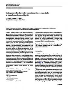
In order to achieve Software Structure Coverage Analysis for a level A system1, testing would have to cover every instruction and modified condition/decision coverage (MC/DC coverage) would have to be adopted. To clarify, certifying a development tool such as a code generator does not mean proving the correctness of the tool. Instead, it demands a high level of quality assurance which, if applied thoroughly, leads to the desired level of software quality. Here, it is important to keep in mind that no specific quality assurances such as program checking, testing etc. are required within most certification standards. Instead, the decision as to which methods are appropriate is left to the software developer, since the most suitable quality assurance method strongly depends on the software to be developed. However, as Ranville stated (Ranville, 2002), “Once an automatic code generation tool is certified as functioning correctly, the code generator can always be assumed to faithfully translate the functionality defined in the model”. This also means that incorrect modelling of functionality by the developer (e.g. 1+1=3) must lead to incorrect functionality within the code (since the model is the specification). In order to be able to fulfil the necessary quality assurances we first need the requirements. Later we will see that formal specifications are a better way to describe the tool’s behaviour than ambiguous textual descriptions. Beforehand, I would like to examine the code generation process in order to provide an idea of the code generator’s behaviour. Implementation model
Target code /* pictrl */ #define "dstypes.h #define G1 (Int32)0x void pictrl(UInt16 r { Int16 e,S2,G_1,x1, UInt8 i; e = (Int16)(ref >> G_1 = (Int16)(((a> x1 = (e >> 4)+x1; G_2 = (Int16)(((a> *u = G2 + G1; }
Simulink
/ Stateflow
graphical notation 1
graphical notation 2
Raw abstract syntax (Source)
code generation process Abstract syntax (Source) Type checking
Intermediate language 1
Transformation
...
Intermediate language n
Transformation / Optimisation
C-Code
Abstract syntax (Target) Optimisation
Fig. 1 The code generation process.
4. The Code Generation Process A code generator is essentially a compiler, since it translates a source language (a graphic modelling or programming language) into a target language (C or ADA code). In contrast to a compiler, however, the input language is substantially more complex, since it does not exist in linear and textual form, but must rather include data flow information, evaluation sequences of functional units (blocks) and graphic layout information (see Fig. 1).
1
This is the most critical category in an avionics system. A system failure prevents continued safe flight and landing. Journal of Integrated Design and Process Science
Vol.8, No. 2, pp. 4
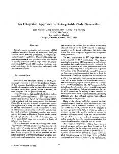
The input of a code generator is a so-called implementation model, which is an enhancement of the physical model (ref. introduction), whereas the data types and the arithmetic are scaled to the arithmetic of the target processor (e.g. 16-bit fixed-point arithmetic). The different modelling languages (Simulink or Stateflow) are intermediately represented in a raw abstract syntax (i.e. a directed, attributed graph). In the translation process the intermediate graph representation of the model is improved with several optimisation techniques and transformed stepwise from a graph to a syntax tree and finally to linear code such as C or ADA. At all transformation stages, different optimisation techniques are applied to the intermediate language (1..n) until the final, processor-specific target code has been produced. One of the reasons most often given for refusing a certification of code generation tools is their complexity and lack of clarity as to how transformations, in particular optimisations, interact with each other. Therefore, having a formal specification is one of the most important prerequisites for certification. First, however, let us examine how code optimisations affect the translation process (see Fig. 2) in order to understand how they could be described (i.e. specified) formally. In the first step of the translation process as shown in Fig. 2, the high-level intermediate representation G (2) of a source model (1) is improved with optimisation techniques such as constant folding. The resulting graph Gopt (3) (the folded constant is depicted as a dashed line) is transformed stepwise into a syntax tree T (4) by applying several optimisation techniques such as dead path elimination or code reuse for subsystems. The optimised syntax tree Topt (5) (low-level representation) finally leads to executable code (6) using processor-specific code patterns. Source model G
1
2
+
T
4
3
Topt *
T1 T2
5 T3
Gopt
pattern x
+
Target code pattern y
int FCN ( ... ) { ... }
6
Fig. 2 Optimisation techniques applied during code generation.
5. Specification of Code Generator Transformations As stated previously, the tool requirements (i.e. specifications) are the prerequisite for verification activities. Since natural language is informal and ambiguous, formal and abstract specifications are more appropriate. The translation process follows a phase model in which each phase is separated by special pre-conditions and post-conditions. Within each phase, special patterns of the internal model representation are replaced or transformed (e.g. a graph pattern into a tree pattern). Graph rewriting rules seem to be an adequate method for describing such patterns for several reasons: • They allow a formal description of the transformation steps in a high-level and abstract language. Transactions of the SDPS
Vol.8, No. 2, pp. 5
• • •
They are easier to understand and less ambitious than textual descriptions. The consistency of interacting graph rewriting rules can be verified. They are suitable for deriving test cases. The application of graph rewriting rules is a known technique in compiler construction. In most cases, the intermediate representation of a program is a set of trees which are rewritten in the code generation phase by techniques such as Bottom Up Pattern Matchers (BUMP, ref. Emmelmann, 1992) or Bottom Up Rewrite Systems (BURS, ref. Nymeyer and Katoen, 1997). Graph rewriting systems could be applied if the code generation process needs to be proven to be correct (e.g. Glesner, et al., 2002) or if the aim is to generate an optimiser from the specification of optimisation rules (Assmann, 2000). In the following, this known pattern-based approach is used to specify transformation steps within a code generator as a basis for the testing activities.
1
const
3
4
sum
2
const
5
4
const
LHS
RHS
action: 5.value= 1.value + 2.value ;
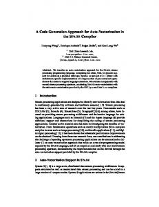
Fig. 3 Graph (rewriting) pattern for constant folding. A graph (rewriting) pattern (see Fig. 3) consists of two parts: a left-hand side (LHS) part (search pattern) and a right-hand side (RHS) part (replace pattern). When an instance of the pattern specified within the LHS is found, logical applicability conditions2 are checked to see whether the transformation can be applied. If the conditions are satisfied, the LHS patterns will be replaced with the pattern stated on the RHS. Finally, the action part specifies which operations must be adopted on the graph instance found in order to obtain a successful result. In Fig. 3, a constant folding optimisation technique for a summation is depicted. On the LHS, four indicated nodes (1..4) are connected via edges to form a search pattern for two constant values referring to a summation node. Each node has an attribute (value) holding the quantity of a constant value (node 1 and 2) or the result of the summation (node 3). On the RHS, the resulting graph of the operation can be found on which a newly created node (5) contains the result of the summation (1.value + 2.value). The nodes 1, 2 and 3 are no longer needed and thus deleted. Since constant folding is a local optimisation technique an example for a global optimisation such as dead code elimination should be given (ref. Fig. 4): The LHS part of the graph pattern depicted in Fig. 4 matches nodes (such as node 2) which have no edges connected to other elements (crossed-out node 3) whereas the matched node could be referenced by other (dashed) nodes (1). The RHS part of the graph pattern is empty since the matching graph (i.e. the dead code) has to be deleted. Finally, logical applicability conditions are stated in the condition line (i.e. “node 2 is not of type OutPort”). By bearing such rules in mind it is possible to specify simple as well as complex optimisations which are used in a code generator. Within the context of verifying a specific optimisation rule, all the 2
E.g. node 1 and node 2 are of type integer. Journal of Integrated Design and Process Science
Vol.8, No. 2, pp. 6
information needed for deriving test cases could be derived from such patterns: the LHS and the conditions can be used to designate the pre-conditions whereas the RHS and the action part are suited to determining the post-conditions.
1
2
3 LHS
RHS
Condition: 2.node_type ≠ OutPort
Fig. 4 Graph (rewriting) pattern for dead code elimination.
6. Test of Specific Transformation Rules In this section I shall use the patterns previously specified to determine test cases. Within this context the main objective is the possible input space for the LHS of a graph-rewriting rule. Domainoriented test derivation techniques such as the Classification-Tree Method (CTM) developed by Grochtmann and Grimm (Grochtmann and Grimm, 1993) seem to be appropriate for this purpose. The CTM (a further development of partition testing) is an approach to deriving abstract test-case specifications from a given specification. The basic idea behind this method is to split up the input domain of a test object into partitions (called classifications) according to different testing aspects and to subdivide these partitions into equivalence classes (i.e. the leaves in the tree). These classes are then recombined and instantiated to form the test data. Constant folding node
const
test cases
0 1 2 3 4
1
2 [3..max]
sum
1 positives negatives
Fig. 5 Classification tree for constant folding. To give the reader an idea of the method, a simplified classification tree (CT) for constant folding (ref. Fig. 3) is shown in Fig. 5 (upper part). Regarding the LHS of a graph pattern, the input domain Transactions of the SDPS
Vol.8, No. 2, pp. 7
can be partitioned into nodes which should be matched (these are the classifications). The classifications are subdivided into classes which state the number of possible occurrences of each node. A recombination of these classes (i.e. test case derivation) allows us to specify how these nodes reference each other. With respect to the classification tree depicted in the upper part of Fig. 5, the name of the test object itself forms the root node (here: constant folding). The input domain consists of nodes divided into classifications such as const and sum (here, edges are not aspects of the input domain since referencing edges are derived implicitly from the abstract test cases). The number of possible nodes is separated into appropriate ranges (0, 1, 2 and [3..max]). Aspects of the data type are missing (e.g. integer summation, floating-point summation). Nevertheless, in order to provide a brief overview of the method, they are excluded from the tree. The test cases derived are shown in the lower part of Fig. 5. They are arranged in a kind of table in which each numbered line indicates a test case divided into positives (test case 1 and 2: tests to demonstrate the software's correct functioning) and negatives (test case 3 and 4: tests whose primary purpose is falsification). A dot in each column indicates a special class (or value) for a test case. For example: test case 1 states that two nodes of type const (i.e. constant value) reference the summation node as specified on the LHS of Fig. 3. The CT for dead code elimination (Fig. 6) looks quite similar. However, the test aspect for node 2 is adjusted to the type of the node (OutPort or Other). On the right hand side of Fig. 6, possible instances of test case 1 and 5 are depicted. Dead Code Elimination
Nodes
1
2
test case 1
3
> 0
1 [2;max-1]
OutPort Other
0
1
>
+ >
max 1: 2: 3: 4: 5: 6:
test case 5 >
...
>
+ >
>
Fig. 6 Classification tree for dead code elimination. The CTs presented show the test cases derived concisely and clearly. Nevertheless, this has been performed manually. An improvement on this approach would be to create the CTs and derive test cases automatically, applying different testing heuristics. Testing heuristics could focus on the edges referencing a node or the data types which are related to an arithmetic operation. A way of applying test heuristics with respect to graph rewriting patterns has been presented in Conrad, et al. (Conrad, et al., 2002).
Journal of Integrated Design and Process Science
Vol.8, No. 2, pp. 8
6.1. Further Testing Aspects In the last section, a way of systematically determining and deriving test cases (i.e. executable models) was proposed. However, once all these models have been derived, one has to think about a way of verifying that the code generated from the model behaves in the same way as the model. For that purpose, one has to take the following objectives for the systematic testing of a code generator into account: on the one hand, the functional behaviour (execution results) of the code generated with respect to given (input) test data, and on the other hand, the generated code structure. As shown in Fig. 7, a test case for a code generator is a model. After code generation has been applied, the execution of the generated code (with selected test data) must be observed and compared to a given reference (e.g. the model’s simulation results) with the goal of checking whether or not the executed code and the simulated model behave in the same way. This could be done by applying functional testing procedures (or black-box testing). In addition to this, the code structure must be compared to the structure of the model (structural testing or white-box testing). This must be carried out to check if all the model’s structural elements are present or not and to exclude undesired code fragments. A way of combining this within a test suite is presented in (Stürmer and Conrad, 2003).
" expected output output " expected
model code
+ -
generator
1
Functional behaviour (Black-box approach)
acceptance criteria
Code structure (White-box approach)
output data of model
data test scenario " test code
2
{
/* TargetLink outport: Subsystem/OutPort # combined # Sum: Subsystem/ TC 5 */ *Sa1_OutPort = (Int16)(((UInt16)Sa1_InPort3) + ((UInt16)Sa1_InPort4)); /* TargetLink outport: Subsystem/OutPort1 */ *Sa1_OutPort1 = Sa1_InPort5; /* TargetLink outport: Subsystem/OutPort2 # combined # Sum: Subsystem/ TC 4 */ *Sa1_OutPort2 = (Int16)(Sa1_InPort6 + SaROOT_FX_GROUND); }
Fig. 7 A code generator’s test objectives. There are, however, more aspects which should be taken into account when testing a code generation tool. Test suites are designed to test different aspects of the code generator under test. According to Boujarwah and Saleh (Boujarwah and Saleh, 1995) test suites must consist of correct test cases (here: models) that should cover both the formal and informal specification of the input language. Furthermore, they must contain incorrect models to ensure that the code generator detects all possible errors and generates the appropriate error messages. Since the input languages for a code generator (e.g. Simulink and Stateflow) are not formally defined or published, such requirements are not suitable. Therefore, the following aspects, beside the main test objectives, should be taken into account when testing a code generator thoroughly: (1) It should be guaranteed that the tool’s basic functionality has been tested rigorously and that known bugs do not reoccur within a new program version. (2) The code generated should conform to accepted and required standards (e.g. ANSI C) and guidelines (e.g. MISRA C).
Transactions of the SDPS
Vol.8, No. 2, pp. 9
(3) The code generator should be robust with respect to complex models, complex optimisations etc. (4) Known problems with compilers should be considered such as floating point operations with NaN (Not a Number) data types and possible division by zero. 6.2. Process Integration As previously shown, testing is an important and appropriate method for assuring desired tool behaviour. However, testing can only be efficient (in an industrial sense) if the testing process can be (partly) automated. It is possible to realise a testing process for a code generator with respect to certification by employing an automated test suite as used for the certification of C and ADA compilers. Tool certification with an automated test suite improves tool integration into the modelbased development tool chain for the following reasons: First, the test of the controller software to be developed and the tool itself are separated. Hence, quality assurance can focus on testing the controller software. Second, it is possible, on the one hand, to ensure the code generator’s correct functioning for each new version and, on the other hand, to verify whether or not the code generator produces the desired code for each project with respect to project-specific options selected in the code generator (e.g. the optimisation level). Third, a certified code generator helps to improve confidence in the selected tool on the part of the developers as well as the customer. Finally, if the test suite is generally accepted by different companies (using autocode tools) the test suite might help to certify different tools regarding other input languages. 7. Conclusion Code generation holds the promise of reducing much of the time and effort required to design and implement embedded software, while at the same time eliminating errors introduced in these stages of development. In this paper, a test case determination approach as a basis for the verification of a code generator’s correct functioning has been suggested whereby test-case derivation is based on a formal specification, i.e. graph rewriting rules. The description of the possible input domain of the transformation rules with the Classification-Tree Method is a suitable means of creating input models which test transformations efficiently and effectively. With respect to the actual certification situation for development tools, automated test suites based on formal specification such as graph rewriting rules, could have an important impact on the acceptance of code generation tools in the context of software development for embedded systems, as has been shown in this paper. However, although the specification of the translation process represents critical vendor know how, tool suppliers must be persuaded to specify their tools in a formal way. It is not unusual for the specification to exist in the developers’ minds only. Therefore, developers should consider the advantages of the method proposed which can be summed up as follows: First, the visualisation of complex code transformations would help tool vendors to make their tool behaviour clear to independent certification authorities. Second, specifications based on well-known techniques such as graph grammars are formal and thus verifiable. Third, it is easy and effective to derive test cases directly from graph-rewriting rules. Furthermore, these test cases are appropriate for testing the most critical part of a code generation tool and are the most suitable way of generalising results obtained.
Journal of Integrated Design and Process Science
Vol.8, No. 2, pp. 10
8. References Assmann, U., 2000, "Graph Rewrite Systems for Program Optimization", In ACM Transactions on programming Languages and Systems (TOPLAS), Vol. 22 ( 4),. ACM Press, pp. 583-637. Beizer,B., 1983, “Software Testing Techniques”, New York, Van Nostrand Reinhold. Boujarwah, A. and Saleh, K., 1995, "Correctness and Completeness of Compiler Test Suites", Proceedings of the 2nd Intern. Conf. on Electronics, Circuits and Systems (ICECS), pp. 272-277. Broekman, B. and Notenboom, E., 2003, "Testing Embedded Software", Addison-Wesley. Conrad, M., Dörr, H., Schürr, A. and Stürmer, I., 2002, "Graph-Transformations for Model-based Testing", GI-Lecture Notes in Informatics, P-12, pp. 39-50. dSPACE, 2002, TargetLink Production Code Generation Guide, Vol. 1.3, dSPACE, Inc. Emmelmann, H., 1992, "Code Selection by Regular Controlled Term Rewriting", In R. Giegerich and S.L. Graham, editors), Code Generation – Concepts, Tools, Techniques, Workshop in Computing, Springer-Verlag. Glesner, S., Geiss, R. and Boesler, B., 2002, "Verified Code Generation for Embedded Systems ", Electronic Notes in Theoretical Computer Science, Vol. 65 No. 2. Grochtmann, M. and Grimm, K., 1993, "Classification-trees for partition testing", Software Testing, Verification and Reliability, 3 (2), pp. 63-82. Hornof, L. and Jim, T., 1999, "Certifying Compilation and Run-time Code Generation", Higher Order and Symbolic Computation, Vol. 12(4), pp. 337-375. MathWorks, 2002, RealTime-Workshop User Guide, The MathWorks, Inc. Necula, G. C., 2000, "Translation Validation for an Optimizing Compiler", Proceedings. of the ACM SIGPLAN Conference on Programming Language Design and Implementation, pp. 83-95. Nymeyer, A. and Katoen, J.-P., 1997, "Code Generation based on formal BURS theory and heuristic search ", Acta Informatica 34, pp. 597-635. O'Halloran, C.and Smith, A., 1999, "Verification of picture generated code", Proceedings of the 14th IEEE International Conference on Automated Software Engineering , IEEE Computer Society, pp. 127-136. Pnueli, A., Shtrichman, O. and Siegel, M., 1998, "Translation Validation: from SIGNAL to C", in K.G. Larsen, S. Skyum, and G. Winskel, editors, Proc. of the 25th Int. Colloquium on Automata, Languages, and Programming (ICALP 1998), volume 1443 of Lecture Notes in Computer Science, page 235-246, Springer-Verlag. Rau, A., 2000, "Potential and Challenges for Model-based Development in the Automotive Industry", in Business Briefing: Global Automotive Manufacturing and Technology, pp. 124-138, 2000. Ranville, S., 2002, "Practical Application of Model-Based Software Design for Automotive", Vehicle Software, Society of Automotive Engineers (SAE), Inc. Sp-1660, pp.37-41. RTCA, 1992, "Software Considerations in Airborne Systems and Equipment", DO-178B, Requirements and Technical Concepts for Aviation, Inc. SCADE, 2003, Esterel Technologies, http://www.esterel-technologies.com. Stürmer, I. and Conrad, M., 2003, “Test Suite Design for Code Generation Tools”, Proc. of 18th IEEE Int. Conference on Automated Software Engineering (ASE 2003), pp. 286-290. Toeppe, S., Ranville, S., Bostic, D. and Wang, C., 1999, "Practical Validation of Model Based Code Generation for Automotive Applications", 18th AIAA/IEEE/SAE Digital Avionics System Conference.
Transactions of the SDPS
Vol.8, No. 2, pp. 11