Integrity Management in Component Based Systems - CiteSeerX
Recommend Documents
Management, CBSE, Component Specification. ... Historically, software configuration management is ... The basic. SCM support includes version management,.
modules to the operating system, both in kernel and user ... Nevertheless, a high-level model for operating system ..... located in a central node on the network.
Email: [email protected]. Abstract. Component-based software .... EDM denotes context or environment dependency matrix. We call all these ma- trice feature ...
The idea of a 'national integrity system' (NIS) was invented by Transparency ...... National Integrity System' http://www.transparency.org/sourcebook/index.html.
spite of the absence of independent electoral commissions in most countries. Yet ... executives and two Presidential systems, two hybrids (Kiribati and Marshall Islands), ..... It was ranked at 102 of 145 countries, tied with Eritrea, Philippines, ..
systems software for a medium-sized cluster with unusu- ally complex .... lowing is a list of components defined by the Scalable ... with accounting systems. 5.3.
fly-by-wire in Avionics, drive-by-wire in Automotive and so on. Given the high ... reliability as the probability of failure-free functioning of a software component.
Software architecture is one of the critical issues in software engineering. In this paper, we will use the .... the formal foundations of expressions3 . To assist with ...
While there is no universal approach to this synthesis, a number of technologies have emerged: SunSoft's Java,. Microsoft's DCOM, and OMG's CORBA, to name ...
Jun 9, 2008 - Our approach for compositional verification of invariants is based on the ..... Breaking up is hard to do: An evaluation of automated assume- ...
Jun 28, 2012 - Software component model, incremental construction, com- ponent composition. 1. INTRODUCTION. The general context of this paper is ...
factory) to a wide variety of application contexts (cars, ships, planes) and it can be ... components and connectors found in architecture definition languages ...
Embedded systems cover a large range of computer .... of all systems is increasing importance of software. For ... of control, monitoring and optimization systems.
MFC40.dll and MFC42.dll can be used for version 4.0 and. 4.2. This prevents .... designed an application on Windows NT 4.0, Dependency. Browser which ...
To appear in Lecture Notes on Computer Science, Springer-Verlag ... Software Engineering Institute, Carnegie Mellon University, Pittsburgh, USA ..... of this port, Java RMI transparently embeds (tunnels) the RMI request in a HTTP request.
ku.edu/kusp/kusp docs/gs internals manual/index.html. [15] M. Friesbie, D. Niehaus, V. Subramonian, and C. Gill, âGroup. Scheduling in Systems Software,â in In ...
the combination of different software systems supporting business processes. The pre- ... Based on the underlying research, the present paper suggests com-.
in the use of software in business, industry ... robustness, simple installation and integration become ... challenges, software development must be able to cope ...
Abstract. Common productivity applications such as Word and PowerPoint, export ..... by executing a script (e.g., JavaScript-enabled dynamic Web pages).
Automatic Performance Management in Component Based Software Systems ... of the business logic code alone, as the component containers have a ...
applications such as Web browsers, text editors, software development tools, and so forth. Often, building and installing a new software package requires ...
systems support definition, management and execution of workflows. .... GraphicalInterfaceMgr: responsible for user interface management. ..... [20] Object Management Group â OMG Document: UML 2.0 OCL 2nd Revised Submission â.
software technology has concentrated on developing infrastructure capabilities ... tools that support specification of business components using techniques that ...
Tests show that this componentisation does not effect the latency or ... The transport framework presented in this thesis is similar to that used by Regis. ...... and connectors are implemented in Python [Rossum95], an interpreted scripting.
Integrity Management in Component Based Systems - CiteSeerX
is the definition of a component based software architec- ture for the ... High volume embedded appliances vary from .... A Robocop service may define several interfaces. We ..... The repair script can add executable component models that.
Integrity Management in Component Based Systems Johan Muskens and Michel Chaudron Department of Mathematics and Computer Science, Technische Universiteit Eindhoven, P.O. Box 513, 5600 MB Eindhoven, The Netherlands E-mail: [email protected], [email protected] Abstract There is a need for mechanisms for maintaining and restoring software integrity on deployed systems. Dynamic replacement, removal and addition of components in deployed systems is supported by most component models. This is needed to enable the software on a device to evolve in the period that it is owned by a consumer, but endangers the integrity of the software on these devices. For high volume consumer devices the challenge is to keep the devices operating reliable and robust in the period that it is owned, used and possibly reconfigured by a consumer. To this end, we propose mechanisms and tools, for maintaining system integrity on deployed systems.
and its components with respect to fault-, power- and terminal management related aspects. Our contribution to the Space4U project focuses on the terminal management activities. In the context of Robocop and Space4U, a terminal is a high volume consumer device. Its management focuses on the period that a terminal is owned and used by a consumer. Integrity refers to functional aspects of the software inside the terminal but also to timing issues and resource use. E.g, after adding or replacing components into the component framework the terminal must remain working according to its specification. In order for the architecture to support the requirements discussed before, we need an architecture that supports:
1. Introduction
• maintaining a model of a terminal to reason about itself and to verify it against a preferred state;
Our research was carried out in the context of the Robocop and Space4U projects1 . The goal of these projects is the definition of a component based software architecture for the middleware layer of high volume embedded appliances. High volume embedded appliances vary from cellular phones and personal digital assistant to Internet and broadcast terminals like set top boxes, network gateways and digital television sets. Where the Robocop project solves a number of critical issues like the enabling of software IP exchange and supporting (distributed) developments based on resource constrained, robust, reliable and manageable components, the Space4U project extends on this goals by including the awareness of the framework 1
These projects are funded in part by the European ITEA program. These are a joint projects of various European companies, together with private and public research institutes.
1.2. Motivation and Research Question There is a need for integrity management mechanisms. Software systems must be robust and reliable. Now software systems are continuously evolving; both during their development as well as during deployment. Component models provides means for the dynamic replacement, removal and addition of components in a deployed system, to cater for an increasing demand for flexibility. This facility endangers the software integrity of the system. Our research question is: How to ensure robust and reliable operation of dynamically changing software systems? The integrity management mechanisms described in this paper provide means for maintaining and restoring integrity in order to achieve robust and reliable operation of a device.
1.3. Overview In this paper we describe our approach for integrity management. We divided integrity management into monitoring, diagnosis and repairing. A ’self-model’ externalized by a terminal is the basis for integrity management in our approach. We verify the current state against the preferred state and evaluate non-functional properties based on this ’self-model’. In this paper we will focus on the model used to describe the current configuration of the terminal and how this can be used for monitoring and diagnosis.
TERMINAL
...
App 1
C1
...
Ci
App m
...
APPLICATION LAYER
Cn
MIDDLEWARE LAYER RUN−TIME ENVIRONMENT
Operating System Abstraction
PLATFORM LAYER Device & Hardware Drivers
NETWORK INTERFACE
The remainder of this paper is structured as follows. In section 2 we discuss our view of a terminal. In section 3 we discuss the Robocop component model. In section 4 we discuss the models we use to describe the individual layers of a terminal. In section 5 we illustrate how these models can be used for remote run-time diagnosis of a terminal. Section 6 discusses related work and draws some conclusions.
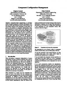
2. Terminals The terminals targeted by Robocop and Space4U are high volume consumer devices. They are assumed to have limited resources (CPU, memory, power, etc). The terminal may, but does not need to be, connected to the outside world through some sort of link and may be mobile or stationary. Obviously a connection to the outside world is required to do remote monitoring and diagnosis. Within a terminal we identify three layers (see figure 1) , a platform layer, a middleware layer and an application layer. The platform layer is considered to be relatively static, whereas the middleware- and application layer are more dynamic. This implies that maintaining system integrity will be done through (re)configuring the applicationand middleware layer. The challenge is to maintain a consistent configuration of these two layers which is suitable for the specific platform. In the remainder of this section we will briefly discuss the individual layers.
2.1. Platform layer The platform layer consist of an operating system, some times an operating system abstraction layer, and some device drivers. The platform layer not likely to change at runtime, but the platform influences which middleware- and application layer configurations are suitable. This means that even though this layer is not likely to change, we do need to take it into account in the monitoring and diagnosis process of the terminal.
Figure 1. Static View on a Terminal
2.2. Middleware layer The middleware layer consists of a run-time environment and a set of executable components. The run-time environment provides the core middleware functionality (registering components, loading of components and unloading of components). The middleware functionality specific for a terminal is provided by a set of components. The set of components can change at run-time. The component model is discussed in section 3.
2.3. Application layer The application layer consists of a set of applications. This set can also change at runtime, for example the user can download a new application. The type of applications is left unspecified. These applications can be ’stand-alone’ or they can require one or more robocop components to fulfill their task. This implies that modifications in the application layer can require modifications in the middleware layer.
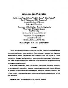
3. Robocop Component Model In this section we will discuss the Robocop component model. The Robocop component model is inspired by COM [1], CORBA [5] and Koala [7]. A Robocop component is a set of possibly related models. (see figure 2). Each model provides a particular type of information about the component. Models may be in human-readable form (e.g. as documentation) or in binary form. One of the models is the ’executable model’, which contains the executable component. Other examples of models are: the resource model (em ∈ EM ) and the behavior model (bm ∈ BM ). The Robocop component model is open in the sense that new types of models can be added.
3.2. Resource model Robocop Component Component Entry Point
Resource Models specify the predicted resource consumption of Executable Components. The Resource Model specifies the predicted resource consumption for all the operations implemented by services of an Executable Component. The resource model contains a number of cost functions. A cost function (Oimp 7→ N) gives the cost (c ∈ N) for an operation (oimp ∈ Oimp ). Per resource r there can be multiple cost functions (r 7→ P(Oimp 7→ N)).
Resource Model Simulation Model Service Manager 1
Provides Interface (I1)
Documentation Function Model Service s1
Service s2
Source Code Robocop Executable Component
...
Requires Interface (I3)
Executable Model
Requires Interface (I2)
RM = Oimp = R =
Executable Model
Figure 2. Robocop component model.
R 7→ P(Oimp 7→ N) S×O set of resources r
(12) (13) (14)
3.3. Behavior model RC M T
= P(M ) × P(M × M × T ) = EM ∪ BM ∪ RM ∪ . . . = M ODELT Y P E × M ODELT Y P E × N AM E we assume there is a function ϕ ϕ : M 7→ M ODELT Y P E
(1) (2) (3)
3.1. Executable model
BM
A executable component offers functionality through a set of ’services’ (∈ P(S)). (see figure 2). Services are static entities that are the Robocop equivalent of public classes in Object-Oriented programming languages. Services are instantiated at run-time. The resulting entity is called a ’service instance’, which is the Robocop equivalent of an object in OO programming languages. EM
=
P(S)
(4) (5)
A Robocop service may define several interfaces. We distinguish a set of ’provides’ ports and a set of ’requires’ ports. The first defines the named interfaces that are implemented by a service. The latter defines the named interfaces that a service needs from other services. An interface is defined as a set of operations. S P N I O
= = = = =
Behavior Models specify the behavior of Executable Components. The Behavior Model specifies the behavior for all operations implemented by services of an Executable Component in terms of operations on interfaces. The behavior b is modelled as a sequence of operations (b ∈ O∗). The behavior is specified for an operation implementation (oimp ).
P(P ) × P(P ) N ×I ST RIN G P(O) set of operations o
(6) (7) (8) (9) (10) (11)
=
Oimp 7→ O∗
(15)
4. Model of a Terminal Our approach focuses on integrity management based on a model of a terminal. Terminals are very complex things that contain a large number of details. We use a model to abstract from the details and to simplify the complex things we are dealing with. In our approach terminals maintain and externalize a self-model. In section 5 we describe how these models are used for managing integrity. Next we will describe our model for the context and the terminal. In this paper we use the following convention: Sets are identified in uppercase, elements out of these sets are identified in lowercase. For example, T is the set of all terminals and t ∈ T identifies one specific terminal. The context is determined by the configuration of the terminal(t), the user(u) using the terminal, the time(θ) at which the terminal is used and the environment(e) in which the terminal is used. We model the a specific context c ∈ C as follows: c =< t, u, θ, e >. C
=
T ×U ×Θ×E
(16)
In the remainder of this section we will discuss the models for the terminal, user, time and environment individually.
4.1. Terminal model
pliant with another (s1 ), therefore we model a complies relation as follows: complies =< s1 , s2 >
Within Robocop and Space4U we distinguish an application layer, middleware layer and platform layer on a terminal. We model these layers individually. In our model a terminal t ∈ T is modeled as follows: t =< al, ml, pl > T
=
AL × M L × P L
(17)
4.1.1. Application layer model The application layer (al) is modeled as a set of applications. Each application a is described by a name, a version, its dependencies d on services and the structure that it will create when launched. The dependencies of an application are modeled by a set of services (d ⊆ S) that are needed by the application in order to execute. Services provide their functionality through a number of named interfaces called ports. In order to provide this functionality a service might require functionality from other services. This dependency is made explicit through the use of required ports, which are also named interfaces. We model a service s ∈ S as follows: s
=
< provided, required > where provided ∈ P(P ) and required ∈ P(P )
The structure of an application consists of a set of service instances (ssi ∈ P(S)), services that will be instantiated at run-time and the bindings (sb ∈ P(B)) between these services instances. A binding (b =< si1 , p1 , si2 , p2 >) between two service instances (si1 and si2 ) means that two ports are connected, a required port (p1 ) of one service instance to a provided port (p2 ) of another. AL = P(A) (18) A = N AM E × V ERSION ×(19) D × ST RU CT U RE N AM E = ST RIN G (20) V ERSION = ST RIN G (21) D = P(S) (22) ST RU CT U RE = P(SI) × P(B) (23) SI = S × N AM E (24) B = SI × P × SI × P (25) 4.1.2. Middleware model The middleware layer is consists of a run-time environment (runtime), a set of registered executable components models (sem ∈ P(EM )), and a set of complies relations between services (sc ∈ P(COM P LIES)). The run-time environment is modeled by its version number. An executable component model is modeled by the a set of implemented services (ss ∈ P(S)). A complies relation consist of one service (s1 ) that is com-
ML = RU N T IM E EM COM P LIES
= = =
RU N T IM E × P(EM ) × P(COM P LIES) V ERSION P(S) S×S
(26) (27) (28) (29)
4.1.3. Platform model The platform layer consists of an operating system (os), a cpu, and storage. The operating system is identified by its name and version. The cpu is identified by its vendor, the f amily that its part of, the clockspeed, and its cachesize. Storage consists of memory, swap and a set of file systems. Each file system is modeled by its name and size. PL = OS = CP U =
V EN DOR F AM ILY M ODEL SP EED CACHE ST ORAGE
= = = = = =
M EM ORY SW AP FS
= = =
OS × CP U × ST ORAGE N AM E × V ERSION V EN DOR × F AM ILY × M ODEL × SP EED × CACHE ST RIN G ST RIN G ST RIN G N N M EM ORY × SW AP × P (F S) N N N AM E × N
(30) (31) (32)
(33) (34) (35) (36) (37) (38) (39) (40) (41)
5. Remote Diagnosis of a Terminal Software systems are continuously evolving; both during their development as well as during deployment. To cater for an increasing demand for flexibility, the Robocop architecture provides means for dynamic replacement, addition, and removal. In Robocop, as well as in other component models, service interfaces and service implementations are separated to support ’plug-compatibility’. This allows for different services, implementing the same interfaces to be replaced. This facility introduces the task of maintaining a consistent software configuration that is suitable for the terminal. This task involves: • monitoring of the current software and hardware configuration of the terminal; • verifying the real configuration against a preferred state (diagnosis); • restoring a preferred state (repairing).
the terminal t that are on the blacklist Sb . Terminal Manager DiagnoseTerminal
service blacklist (∪em : ml =< x, y, z > ∧ (em ∈ y)) ∩ Sb where t =< al, ml, pl >
(42) (43)
Executable component models that provide services compliant with the services in DBoS (t) are needed for the generation of the repair script. These compliant services should not be on the blacklist themselves. The database role can provide suggested replacements for the services that are on the blacklist.
Status
5.2. Blacklist of Complies Relations Figure 3. Integrity Management of a Terminal.
Using the model for a terminal as described in section 4 we are able to monitor the configuration of a terminal and verify it. This diagnosis process is illustrated by figure 3. The basis for this process is the model for a terminal. This model is externalized by the terminal and can be fetched by a terminal manager. The terminal manager has access to a database with rules and solutions. The rules indicate desired and undesired configurations. Solutions describe recipes to migrate from an known undesirable state to a desirable state. Using this information a diagnosis can be made and if necessary a repair plan can be generated and executed based on the diagnosis. In the remainder of this section we will discuss a number of example checks that can be used during diagnosis, and how the detected problems can be repaired. In this paper the focus will be on the diagnosis.
The set of compliance relations represents the knowledge of the middleware about the compatibility of services. If this knowledge is incorrect this can result into errors. When it is discovered that a complies relation is incorrect after it has been published then the relation can be ’deployed’ on a unknown number of terminals. We propose to maintain a blacklist of published complies relations that are incorrect, such that they can be removed during the terminal management activities. DBoC (t) is the (partial) function that takes an element t ∈ T and gives the set of complies relations registered in the middleware of terminal t that are on the blacklist (Cb ). Cb DBoC
= =
complies blacklist (44) (∪c | ml =< x, y, z > ∧c ∈ z) ∩ Cb (45)
The repair script will remove the complies relations that are element of DBoC (t). After this complies relation is removed the repair script will check whether there are no missing services.
5.3. Missing Services 5.1. Blacklist of Services During the life-cycle of a component bugs in the services that they provide can be discovered. When the bug is discovered after the component has been published then the component can be deployed on an unknown set of terminals. It is impossible, undiserable and probably illegal to track the deployment of every component. We propose to maintain a database that contains the services in which a bug has been discovered, such that these services can be replaced by the terminal management activities. DBoS is a (partial) function that takes an element t ∈ T and gives the set of services provided by the middleware of
Applications can require a number of services to fulfill their task. In a dynamically changing terminal, to which new applications are downloaded and from which applications are removed, it can be hard to keep the set of services provided by the middleware consistent with the applications. We will now discuss how to verify that all required services are provided by the middleware based on the application layer- and middleware layer model. DMS (t) gives the set of services that are needed by one or more applications on terminal t but that are not provided by the middleware of terminal t. DMS (t) is the difference between Sr (t) and Pc (t). Sr is the set of services that is required by the set of applications that is available on terminal t, this comes down to the union of the dependencies of these applications. Pc (t) is the set of services that can be
provided by the middleware of terminal t, this comes down to union of the set of services provided by the middleware with all the services that are compliant with the services provided by the middleware according to the complies relations that are registered. Pc (t)
Sr (t)
DMS (t)
= (∪em : ml =< x, y, z > ∧(em ∈ y))(46) ∪ {s1 ∈ S | (s2 , s1 ) ∈ (∪complies : ml =< x, y, z > ∧(complies ∈ z)) ∧ s2 ∈ (∪em : ml =< x, y, z > ∧(em ∈ y)) } where t =< al, ml, pl > = {s ∈ S | s ∈ d ∧ (47) < name, version, d, structure >∈ al } where t =< al, ml, pl > = Sr (t) \ Pc (t) (48)
Generation of the repair script can be straight forward. The repair script can add executable component models that provide the missing services or remove the applications that require these missing services.
5.4. Memory Exhaustion Using this diagnosis we check that there is no application on the terminal that consumes more resources that are provided by the terminal. The platform layer model provides the number of resources provided by the terminal. We predict the resource consumption of an application using the resource prediction technique described in [4], and [6]. In the remainder of this subsection we will discuss how this resource prediction technique can be combined with our approach for remote run-time diagnosis. 5.4.1. Per Operation Resource Specification We predict resource usage based on resource models, behavior models, and a scenario specification. The resource consumption of oimp , an operation o implemented by service s ∈ S provided by an executable component model em ∈ EM is specified in a resource model rm ∈ RM . rc
=
oimp
=
< sm, smr > (rm ∈ sm) ∧ (em ∈ sm) ∧(< rm, em, ”rm of” >∈ smr) s ∈ em rc ∈ RC < o, s >
{claimcpu }where cpu ∈ R {claimmem , releasemem } where memory ∈ R amount of cpu claimed by oimp amount of memory claimed by oimp amount of memory released by oimp
5.4.2. Per Operation Behavior Specification The behavior (o1 ; . . . ; on ) of an operation o of service s provided by executable component model em can be found in behavior model bm, assuming that bm is the behavior model of bm.
rc
oimp bm(oimp )
= < sm, smr > (bm ∈ sm) ∧ (em ∈ sm) ∧ (< bm, em, ”bm of” >∈ smr) s ∈ em rc ∈ RC = < s, o > = behavior of oimp
5.4.3. Per Operation Resource Estimation We are able to deduce the behavior of a scenario based on the set of services established by an application and the specified behavior of the operations of these services. We determine the resource use of called operations, using this scenario behavior and the specified resource consumption per operation. To that end, we define a weight function w using ’resource combinators’. This function calculates consumption of a resource r of an operation o over a composition of services (application), by accumulating the resource usage of o itself, and of the resource consumption of all the operations that are called by o.
w(o, s, r)
=
(x, y) where (49) x = claimmem (oimp ) y = releasemem (oimp ) (claimmem ∈ rm(memory)) (releasemem ∈ rm(memory)) oimpl =< s, o > r = memory rc =< sm, smr > (rm ∈ sm) ∧ (em ∈ sm) (< rm, em, ”rm of” >∈ smr) (s ∈ em) ∧ (rc ∈ RC)
pression: w(o, {s1 , . . . , sn }, r) =
w(o, {si }, r) (50) (w(o1 , {s1 , . . . , sn }\{si }, r) ⊕ ...⊕ w(ok , {s1 , . . . , sn }\{si }, r)) where (o ∈ i) ((x, i) ∈ sp) ∧ (si = (sp, y)) rc =< sm, smr > < bm, em, ”bm of” >∈ smr si ∈ em (o1 ; . . . ; fk ) = bm(< si , o >)
In different cases we want to combine the resource usage of the operation executions in different ways. In order to be able to combine the resource usage of operation executions appropriately for each of the cases mentioned before, the resource estimation technique supports resource combinators for each case. The resource combinator ⊕ is used to model resource usage of two sequentially executed operations. The combinator is used to model resource usage as part of an operation. The definitions of these combinators may be varied, in order to deal with different types of resources or to measure resource usage in different ways. In this example we consider memory consumption and therefore define the resource combinators as follows (see [6] for explanation): (a, b) ⊕ (c, d) = (a, b) (c, d) =
(a − b + c, d) if c ≥ b (a, b + d − c) if c < b (a + c, b + d)
(51) (52)
Now we combine the set of services defined by application a and weight function w, to form the weight function Wop , that calculates resource consumption that results from executing an operation. It is defined as: Wop (a, o, i, r) =
w(o, d, r) where a =< x, y, d, z >
(53)
5.4.4. Modeling resource consumption for call sequences Each operation call that is specified in a service behavior specification may be accompanied with an iterator (’?’) to indicate that the operation may be called multiple times. For the purpose of resource estimation, we represent an iterated operation call as a lambda expression: o? =
λl → l × o
(54)
This lambda expression states that operation o is called l times, where l is variable. The weight function for an iterated operator call can now also be defined as a lambda ex-
Such lambda expressions are instantiated with concrete numbers, when resource consumption for a complete scenario is predicted. 5.4.5. Per Task Resource Estimation As part of the resource prediction for a scenario we need to be able to predict resource consumption for a sequence of operation calls. We introduce the notion of a task, which is a sequence of operation calls. A task can be continuous or terminating, a continuous task corresponds to a repeating sequence of operation calls and a terminating task corresponds to a finite sequence of operation calls. Using function Wop we are able to estimate resource consumption for individual operation calls, we need to predict resource consumption of a task. To that end, we need to know what plausible sequences of operation calls are. Such sequences (which we call task definitions), are determined together with implementors of services. If iterated operations are called in a task definition, the task definition becomes a lambda expression. Defining a task therefore consists of the following two steps: 1. Defining a plausible sequence of operation calls; 2. Instantiating concrete numbers for the lambda expressions, if any. Instantiating a lambda expression fixes the number of operation calls. Thus, instantiating a lambda expression λl → l × f with, say, 2 yields a sequence of two calls to f . We can now define the weight function Wt for a task, consisting of sequential operation calls. This function computes for each task, e.g. a sequence of operations, the required resources. Wt (a, f, r)
=
Wt (a, (g; h), r)
=
Wop (a, o, i, r) (56) for operation call f =< i, o > and i ∈ I ∧ o ∈ O Wt (a, g, r) ⊕ Wt (a, h, r) (57) for sequences of operation calls g and h
5.4.6. Scenario-based Estimation In the Robocop component model, multiple executable components can work on different tasks that are executed in parallel. A scenario is defined as a set of tasks. This set contains the tasks that are executed in parallel, and for which the resource estimation needs to be made.
We can now define the weight function W for a scenario S and resource r, consisting of multiple tasks. This function computes for each task the estimated resource consumption: Ws (a, t, r) Ws (a, t1 , . . . , tn , r)
The function W introduces the functions Ws and T S and a new resource combinator ⊗. This resource combinator is used to combine resources that are consumed in parallel. The resources can be combined only after we know what type of scheduling is used. Therefore the introduced resource combinator ⊗ is abstract. It is the task of the function TS to do the scheduling and transform the expression in an expression which only contains concrete operators. 5.4.7. Applications that Exceed available Resources The motivation for estimating the resource consumption for an application a executing a scenario is that we want to be able to check whether the resource consumption of will exceed a certain limit. DREA (t) will calculate the set of applications a on terminal t for which the predicted memory consumption for a critical scenario (W (a, scenario, memory)) exceeds the memory of the terminal. DREA (t)
= {a ∈ al | (61) W (a, scenario, memory) > memory } where scenario is a critical execution of application a ∈ al storage =< memory, x, y > pl = (k, l, storage) t =< al, ml, pl > for arbitrary k, l, x, y
6. Concluding Remarks 6.1. Discussion Most systems must operate reliable and robust. Now systems are continuously evolving, even during deployment. This endangers robust and reliable operation of the system. In this paper we presented an approach for managing the integrity of the software on a device during deployment. Now our approach supports remote monitoring and remote diagnosis of a device. Remote repairing is future work. These mechanisms can be used to maintain software integrity and therefore to increase the robustness and reliability of a device.
Our approach has two major advantages. First of all the diagnosis and monitoring can be done remote as well as local. Combinations are also possible. For example some simple diagnosis is done on the terminal and the more complex diagnosis is done on a remote server. The mechanisms we use are light weight for the terminal concerning processing, network traffic as well as storage. Especially for the embedded domain this is a strong advantage. There are also some open issues that require further research. Now a modest number of checks are available that can be used for diagnosis. We plan to extend this checks. Currently we are working on checks that verify whether the structure of applications adhere to certain design guidelines. Furthermore we observe that the current checks are based on relatively static information. State and configuration of specific instances is not addressed in the current checks. Finally, until now we did little work on repairing the diagnosed problems on a terminal.
6.2. Related work Some work has been done on remote management and configuration of a device. SNMP [2] and SyncML DM [8] are existing device / network management technologies that are widely adopted by industry. These technologies focus on the mechanism needed for remote configuration and adaptation. We focus more on what needs to be adapted (diagnosis) and how (repair script). Some work has been done on architecture based approaches for self-healing systems [9] [3]. These approaches focus on detecting when to make a particular repair based on architectural. In their approach, an architectural style is a set of constraints. Constraint violation is cause for inducing a repair. The difference with our approach is that our approach allows diagnosis and repairing based on different kind of models (resource, behavior, etc). Our diagnosis is not limited to use only the architectural description of a system.
6.3. Contributions In this paper we presented an approach for integrity management. This approach allows monitoring, diagnosis and repairing of the software configuration of a device. Our approach is applicable for component based embedded systems and supports diagnosis and repairing based on architectural descriptions as well as on models describing the extra functional properties of system parts.
References [1] D. Box. Essential COM. Object Technology Series. AddisonWesley, 1997. [2] J. Case, R. Mundy, D. Partain, and B. Steward. Introduction to version 3 of the internet-standard network management framework. Technical Report RFC 2570, SNMP Research, TIS Labs at Network Associates, Ericsson, Cisco Systems, 1999. [3] E. Dashofy, A. van der Hoek, and R. Taylor. Towards architecture-based self-healing systems. In Proceedings of the first workshop on Self-healing systems. ACM, Nov. 2002. [4] M. de Jonge, J. Muskens, and M. Chaudron. Scenario-based prediction of run-time resource consumption in componentbased software systems. In Proceedings: 6th ICSE Workshop on Component Based Software Engineering: Automated Reasoning and Prediction. ACM, June 2003. [5] T. Mowbray and R. Zahavi. Essential Corba. John Wiley and Sons, 1995. [6] J. Muskens and M. Chaudron. Prediction of run-time resource consumption in multi-task component-based software systems. Technical Report TR-117, Technische Universiteit Eindhoven, 2003. [7] R. van Ommering, F. van der Linden, J. Kramer, and J. Magee. The Koala component model for consumer electronics software. IEEE Computer, 33(3):78–85, Mar. 2000. [8] Open Mobile Alliance. SyncML Device Management initiative consolidated into OMA, http://www.openmobilealliance.org/tech/affiliates/syncml/ syncmlindex.html, 2002. [9] B. Schmerl and D. Garlan. Exploiting architectural design knowledge to support self-repairing systems. In Fourteenth International Conference on Software Engineering and Knowledge Engineering, 2002.