This document contains the draft version of the following paper: S.K. Gupta, C.J. Paredis, R. Sinha, and P.F. Brown. Intelligent assembly modeling and simulation. Assembly Automation, 21(3):215-235, 2001. Readers are encouraged to get the official version from the journal’s web site or by contacting Dr. S.K. Gupta (
[email protected]).
Intelligent Assembly Modeling and Simulation Satyandra K. Gupta ∗ Department of Mechanical Engineering and Institute for Systems Research University of Maryland College Park, MD 20742 Email:
[email protected] Tel.: +1-301-405-5306 Fax: +1-301-314-9477 Christiaan J.J. Paredis Institute for Complex Engineered Systems and Department of Electrical and Computer Engineering Carnegie Mellon University Pittsburgh, PA 15213 Email:
[email protected] Tel.: +1-412-268-8299 Fax: +1-412-268-5229 Rajarishi Sinha Institute for Complex Engineered Systems Carnegie Mellon University Pittsburgh, PA 15213 Email:
[email protected] Tel.: +1-412-268-5214 Fax: +1-412-268-5229 Peter F. Brown CommerceNet 10050 N. Wolfe Road, SW2-255 Cupertino, CA 95014 Email:
[email protected]
Total words: 9834 Keywords: Articulation Modeling, Assembly Analysis, Tool selection, Assembly Planning, Simulation, Agile Workforce
∗
Corresponding author
1
Abstract Because of the intense competition in the current global economy, a company must conceive, design, and manufacture new products quickly and inexpensively. The design cycle can be shortened through simulation. Rapid technical advances in many different areas of scientific computing provide the enabling technologies for creating a comprehensive simulation and visualization environment for assembly design and planning. We have built an intelligent environment in which simple simulation tools can be composed into complex simulations for detecting potential assembly problems. Our goal in this research is to develop high fidelity assembly simulation and visualization tools that can detect assembly related problems without going through physical mock-ups. In addition, these tools can be used to create easy-to-visualize instructions for performing assembly and service operations.
1 Introduction The realization of new electro-mechanical devices is characterized by ever shortening times to market, along with increasing customer demand for improved quality. In this business environment, it is important for designers to be able to improve efficiency and reduce the product weight and volume, and pack a large number of components in a very small space. At the same time, in order to make products easier to assemble and service, designers need to leave enough room for performing assembly and disassembly operations. These are often conflicting requirements and make design of electro-mechanical products a highly iterative process. In the absence of high fidelity simulation tools, many product development teams are forced to include physical prototyping in the design loop to verify proper functioning and ease of assembly. Physical prototyping is a major bottleneck. It slows down the product development process and constrains the number of design alternatives that can be examined. Furthermore, after a prototype has been built and tested, a significant amount of time is spent creating instructions for performing assembly and service. Rapid technical advances in many different areas of scientific computing provide the enabling technologies for creating a comprehensive simulation and visualization environment for assembly design and planning. We believe that developing and maintaining a single monolithic system for assembly simulations will not be practical. Instead, we have built an environment in
2
which simple simulation tools can be composed to create complex simulations. Our goal in this project is to develop high fidelity assembly simulation and visualization tools that can detect assembly related problems without going through physical mock-ups. In addition, these tools will be used to create easy-to-visualize instructions for performing assembly and service operations. In our Intelligent Assembly Modeling and Simulation (IAMS) environment, the designer creates an assembly design using a commercial CAD package. After annotating the CAD model with articulation and assembly features, the designer stores the design in the assembly format. The designer then selects a number of simulation tools and composes them into a customized simulation. In parallel, process engineers create a model of the work cell in which the parts will be assembled. The designer proposes an initial, high-level sequence in which this assembly can be performed - either interactively or through the use of assembly planning software. The highlevel assembly steps are converted to detailed assembly planning instructions by an automatic micro-planner. He then uses the simulation environment to analyze the assembly, and he makes changes in the assembly after discovering problems. Currently, the simulation environment includes the facilities for performing interference detection, tool accessibility analysis, and detailed path planning. When the designer is satisfied with the design, the process engineer can optimize the workspace and create a detailed animation of the assembly process. This sequence is downloaded to the operator’s desktop computer, where it can be consulted using a browser. The operator can start assembling the parts immediately, without the need for extensive training.
2 Review of Related Work 2.1 Assembly Representation In order to use computer-aided assembly design and planning systems, we need to have computer-interpretable assembly representations. A number of different approaches have been adopted to represent assemblies (Lee and Andrews, 1985, Lee and Gossard, 1985, Molloy et al., 1993, Shah and Rogers, 1993, Seow and Devanathan, 1994, Lin and Chang, 1990, Minami et al., 1995). In many of these techniques, each individual part is represented by its geometric model, and the assembly is represented by the relative position and orientation of each individual part in
3
the final assembled configuration. Most non-geometric information such as fits or joints is stored as text labels. At present, there is no comprehensive scheme for representing articulated assemblies. In order to do intelligent simulations, we need better assembly representations. In this project, we have developed assembly representations that allow us to capture articulation. 2.2 Design for Assembly This area grew out of the need to create products that are easier to assemble (Miyawaka and Toshirijo, 1986, Boothroyd, 1994, Hsu et al., 1992, Lee et al., 1993, Jakiela, 1989). It was started by the pioneering work of Boothroyd and Dewherst. Several different variations of Boothroyd and Dewherst techniques (Boothroyd, 1994) have been developed over the years. Most systems formulate this problem in the following way: given the description of an assembly, evaluate its goodness and offer redesign advice based on the bottleneck areas. Boothroyd and Dewherst, Inc. offers commercial software based on the early research of its founders. However, most DFA tools are currently not integrated with CAD software, lack abilities to perform geometric reasoning, and fail to detect problems due to interactions with the workspace and tools. Our approach addresses these shortcomings and complements the capabilities of DFA software. 2.3 Assembly/Disassembly Operation Sequencing This body of research mainly focuses on generating feasible assembly or disassembly sequences (De Fazio and Whitney, 1987, De Fazio et al., 1989, Homem de Mello, 1989, Homem de Mello and Sanderson, 1989, Khosla and Mattikalli, 1989, Sanderson et al., 1990, Swaminathan and Barber, 1995, Woo and Dutta, 1991). This research can be further divided into two groups. The first group developed techniques for finding optimal or near-optimal sequences. The second group developed techniques for efficiently enumerating all feasible sequences. In most cases, assembly time or cost is used as the objective function (Klein, 1986, Millner et al., 1994). In many systems, the first step is to create an assembly/disassembly dependency network. This network represents the blocking characteristics of the assembly. Information for creating the assembly/disassembly dependency network can either be supplied by the human or by an automated geometric reasoning system. The next step is to use state-space search techniques for finding the desired solution. Assembly sequences are used for assembling the part. Disassembly sequences are used for creating a maintenance plan or recycling the
4
product (Navin-Chandra, 1991, Navin-Chandra, 1993). Currently, this work does not address tool and process related issues. Our research complements this work by providing a much more extensive set of analysis capabilities. 2.4 Motion Planning This research mainly deals with robot motion planning for robotic assembly (Carriker, 1995, Park and Chung, 1993, Shin et al., 1995). The problem is defined as: given a sequence of assembly operations to be performed, determine a series of robot moves that are capable of executing the given operation sequence and optimize the given objective function (i.e., operation time). In general, the problem of finding the optimal motion plan is shown to be P-space hard. Therefore, quite often the following two approaches are used to simplify the problem at hand. In the first approach, an attempt is made to find an optimal motion path under a restricted set of robot moves.
In the second approach, fast algorithms are developed to find near-optimal
solutions. 2.5 Tool Accessibility To analyze tool accessibility in machining operations, two different approaches have been developed. The first approach checks for interference between the workpiece and the tool accessibility volume, which is defined as the non-cutting portion of the tool (Gupta, 1994, Gaines and Hayes, 1997, Stage et al., 1997). The second approach uses visibility maps (Woo, 1994, Laxmiprasad and Sarma, 1997); a machining operation for a particular face is selected such that the tool approach direction is inside the visibility region for that face. Both approaches have also been applied for coordinate measuring machines, to determine the accessibility of inspection points. The tool accessibility problem has also been investigated for the assembly domain. Homem de Mello and Sanderson’s (Homem de Mello and Sanderson, 1991) model of assemblies include attachments, which describe fastening methods. Four types of attachment are considered: clip, pressure, screw, and glue. Even though the attachments can be used to generate disassembly sequences, the detailed tool movements required to carry out these attachment are not modeled. Diaz-Calderon et al. (Diaz-Calderon et al., 1995) present a method that automatically determines the complexity of an assembly task based on the tool use. The most detailed work is reported by Wilson (Wilson, 1996). Wilson developed a tool representation that includes the tools use volume, i.e. the minimum space that must be free in an assembly to apply
5
Figure 1. System overview the tool. He further divides tools into pre-tool, in-tool, and post-tool classes, based on the time at which the tools are applied relative to when the parts are mated in the assembly operation. In addition, he provides algorithms for finding feasible tool placements.
6
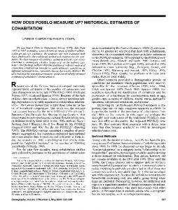
3 System Overview As illustrated in Figure 1, our software environment consists of four major components: (1) an assembly editor, (2) a plan editor, (3) an assembly simulator, and (4) an animation generator/viewer. The assembly editor imports CAD files of individual components from an ACIS-based solid modeling system (http://www.spatial.com, 2001) and organizes them into an assembly representation. Using feature recognition techniques, the assembly editor recognizes joints between parts and assembly features on individual parts. The plan editor described in Section 5 allows users to synthesize assembly plans interactively. The assembly sequence and tooling information (i.e., macro plans) entered by the user are automatically converted into low level tool and part motions (i.e., micro plans). Using the assembly simulator, the user selects and controls various simulations (such as interference and tool accessibility). The animation viewer allows the assembly operators to view the modeled assembly process interactively. The users can randomly access any particular operation in the assembly sequence and interactively change their 3D viewpoint. Practically, these components can be used in the following manner. A designer creates an assembly design using a commercial CAD package. The design is imported into our environment using the assembly editor. The designer then uses the plan editor to enter a specific assembly sequence. The designer selects a number of simulation modules in the simulation controller and composes them into a customized simulation. Based on the feedback from the simulations he may have to change the assembly design. After several design iterations, he is satisfied with the design and hands it over to the process engineer. In parallel, using the workspace editor, the process engineer has created a model of the work-cell in which this assembly will be performed. After incorporating the assembly in the workspace, the process engineer performs a detailed simulation to check for any problems in the final assembly plan. He then generates an animation of the assembly process that is downloaded to the operator’s desktop computer where it can be viewed by the operator using the animation viewer. The operator can start assembling the parts immediately, without the need for extensive training or tedious creation of documentation. Our system has been implemented using C++ programming language. It currently runs on SUN (under Solaris operating system) and SGI workstations. We use ACIS for representing various parts in the assembly model. We use a combination of RAPID (Gottschalk et al., 1996) and ACIS for performing interference tests. We are using OpenInventor for graphical rendering.
7
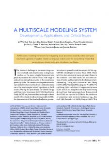
Figure 2. A one degree of freedom scanner We use the LEDA class library (Mehlhorn and Naher, 1995, http://www.algorithmicsolutions.com, 2001) for implementing various data structures. Figure 2 shows the assembly of a scanner. This scanner has one degree of freedom and is used to detect the presence of an object by scanning horizontally. We will be using this example throughout this paper to illustrate capabilities of our system.
4 Assembly Editor Assemblies are a collection of components, which by virtue of their relative positions and orientations satisfy certain functional requirements of the designer. However, specifying the part geometry and the relative positions and orientations of the parts is not sufficient for performing assembly simulations. The designer should be able to annotate each part with additional information that will be useful in the design process, as well as be able to group parts into a single assembly. To address this issue, we have developed an Assembly Editor (shown in Figure 3) that assists the designer in creating a representation of the assembly. Besides the ability to group all the parts into a single data structure, the Assembly Editor provides the designer with the ability to attach attributes to parts (such as color, material name, and density). The Editor automatically identifies
8
Figure 3. Specifying a revolute joint in the assembly editor features on the part that can aid in subsequent tool selection, and incorporates the ability to populate a representation of articulation for each joint in the assembly. Once this is done, two very important tasks during assembly sequence planning and simulation happen seamlessly, with minimal user interaction:
•
Tool selection is based on the part features that have been detected by the Assembly Editor. Depending on the type of feature recognized (such as a Phillips slot), the appropriate tool will be automatically selected and will know how to position itself on the part.
•
Simulation of articulation can now proceed at a very high level, namely, the designer needs only to specify a value for the degree of freedom for a joint, and the system will proceed to articulate it; it is no longer required to mimic articulation by a relative motion of the part by providing a transformation.
9
Figure 4. A Phillips slot feature 4.1 Part Feature Recognition Whether a tool is applicable for a part depends on the features of the part to which it is applied. For example, a Phillips screwdriver can only be used for screwing in a screw with a Phillips slot of the appropriate dimensions. We have developed an algorithm that automatically recognizes the following assembly features: FlatSlot, PhillipsSlot, HexagonalSlot, HexagonalBoss, and CircularHole. The feature recognition algorithm is quite generic because of our canonical representation of features. The representation consists of a parametric base face (with a particular surface type, number of edges, interior angles, and accessibility condition) and a set of neighboring faces. The algorithm loops over all the faces in the solid model and compares each of them with the parametric representation of the features’ base face. If there is a match and the base face needs to be accessible, the algorithm checks for intersections between the normally swept volume of the base face and the rest of the part. Finally, the neighboring faces of the base face are matched with the neighboring faces of the feature template. If all of the above conditions are met, the algorithm extracts features’ reference frame and the values of its parameters. All of the information relating to the features on the part, along with the other attributes of the part form a complete description of the part (see Appendix A.2). Two additional features are required to support automatic tool generation for all the assembly operations: Thread and AdhesiveFace. These features do not have any distinguishing geometric characteristics (a thread is commonly modeled as a plain cylinder); therefore, the user has to identify them and provide their relevant parameters.
10
As an example consider the
Figure 5. Phillips slot feature on a screw PhillipsSlot feature defined in Figure 4 and shown in Figure 5 as part of a screw. The parameter values and reference frame are listed in the description file below: { Part { Color steelblue } { Transform identity } { Material { Name steel } { Density 7.8 } } { Feature { Type PhillipsSlot } { Width 1.5 } { Depth 1.2 } { Length 6.5 } { Reference Transform homogeneous 0 0 4 0 -1 0 1 0 0 } } { Feature { Type Thread } { Pitch 1.5 } # metric thread { Depth 20 } { Hand 1 } # right-handed } }
4.2 Joint Specification Most electro-mechanical products have built-in articulation. Examples include household appliances, computer disk drives, tape drives, satellites, VCRs, etc. Most existing assembly representations do not explicitly model kinematic behavior of the assembly. In order to correctly generate assembly or disassembly plans for such products, we need to take articulation information into account.
11
Figure 6. The contact graph for the missile scanner assembly Before joints can be defined, it is helpful to know which parts are in contact with which other parts. Some subset of these contacts will become joints in the final assembly. From the part geometry, we generate all the possible contacts between the parts, and populate an undirected contact graph, with parts represented as nodes, and contacts as edges. Performing intersections between the nodes automatically derives edges between nodes. Each part is scaled by a measure proportional to its bounding box dimensions, so that the result of the intersection is a regular solid (or a set of regular solids). Some of these contacts will become legitimate joints; the designer can delete others. The graph is pruned to a tree (Figure 6). By default, all the contacts are fixed joints. The contacts that are not fixed joints in the final assembly can be converted to one of the following lower pairs: Revolute (1 Rotational Degree of Freedom (RDOF)), Cylindrical (1 RDOF, 1 Translational Degree of Freedom (TDOF)), Prismatic (1 TDOF), Planar (1 RDOF, 2 TDOF), and Spherical (3 RDOF). For example, the scanner assembly has a revolute joint between the motor and the motor sleeve (Figure 7).
Figure 7. The revolute joint between the motor and the motor sleeve
12
Figure 8. The articulation representation schema We define three levels of articulation representation (Figure 8). The highest level is one of body-to-body contacts, and is obtained from the graph. The contacts can be classified into two types - constraint contacts and incidental contacts (Rajan et al., 1997). Constraint contacts limit the degrees of freedom of the component, and incidental contacts limit the range of motions allowed for each degree of freedom. The intermediate level uses the body-to-body contact information to obtain body-to-body constraints. The result of each intersection is examined for features such as cylindrical faces, or opposing planar faces. The point and line features on these faces form the low-level representation. A complete representation of a joint between two parts in an assembly requires two pieces of information - the position of the joint on each part and a description of the degrees of freedom of the joint. A position vector specifies the position. The degrees of freedom are specified by defining features on the parts, which constrain the relative movement of the parts, and by
13
defining limits on how much constrained movement is allowed. Figure 3 shows a revolute joint being specified in the assembly editor. Representation of the revolute joint in the missile scanner is given by: {Joint Revolute {Name motorsleeve_motor} {JointFeatures {Axis motorsleeve 150 60 85 {Axis motor 150 60 85 14 4244 3
Position of axes
0 0 1
Rotation 678axis
0 0 1
1 0 0} 112 0 30
}
Orientation axis
} {Articulations {Theta 0 -75 75} } }
Joints can be tested using the joint tester window (Figure 3) by selecting the corresponding edge on the contact graph and entering an articulation value for a degree of freedom. Once all the joints are defined and tested for correctness, and unwanted contacts have been removed from the contact graph, the designer is able to save the newly created assembly (see Appendix A.1 for a partial missile scanner assembly file). Now that a complete representation for the assembly is available, the designer can create a workspace and construct an assembly plan.
5 Plan Editor To construct assembly plans for simulation, we need to satisfy two important criteria. On the one hand, we need to create a description of an assembly plan at a level at which humans are able to provide high-level expertise. On the other hand, we need a very detailed description for performing high fidelity simulations. For instance, for a given assembly operation, it is very easy for the user to propose the appropriate tool. However, for simulation purposes, this operation needs to be augmented with detailed information about the position of each of the parts and tools at any time. Our approach is to create automatic plan completion capabilities that bridge the gap between these two requirements and relieve the user from tedious entry of low-level details; these details will be automatically generated by the system. 5.1 Workspace Generation Whether an assembly plan is acceptable or not depends not only on the geometry of the parts, but also on the workspace in which the assembly will be created, and on the tools with which the
14
Figure 9. Workspace for the scanner assembly operations will be performed. It is important that we build comprehensive representations for both the workspace and the tools. For instance, in addition to the tool geometry, our representation captures information about the proper tool usage (e.g., tool orientation or movement). The workspace generator takes the assembly and the tool models as input and synthesizes a working environment that includes: an assembly table, a part rack, and a tool rack. The layout of the environment and the configurations of each of the parts and tools are also determined. All parts and tools are oriented so that their principal axes are aligned with the X, Y, and Z-axes in the world coordinate frame. Identical parts are grouped and placed in a single cell of the part rack. Figure 9 shows the workspace for the scanner. 5.2 Entering High Level Plans To facilitate the generation of detailed assembly process specifications, we have implemented an assembly plan editor. With this editor, the process engineer can specify a high-level assembly sequence, as is illustrated in Figure 10. Such as sequence consists of high-level assembly operations performed on individual parts or sub-assemblies. The operations that are currently supported include: relative and absolute positioning of parts, fitting, extracting, screwing, tightening, soldering, brazing, and coating. When one of these operations is selected, the plan editor will display a customized form in which the user can specify additional information. For
15
Figure 10. A screw operation being specified in the plan editor instance, for a screwing operation, the user is asked for the name of the screw, the tool name, and the duration of the operation. A micro-planner (described in Section 0) will then convert the high-level assembly plan into low-level detailed assembly primitives. For example, a single screwing operation will result in a sequence of assembly primitives starting with the positioning of the screwdriver, engaging of the screwdriver with the screw, the actual screwing, the disengagement, and finally, the return of the screwdriver to the shelf. All the additional information needed to generate such a low-level sequence is extracted automatically from the tool, part and assembly models. Once the process engineer has entered a high-level assembly operation, he can verify the corresponding microplan immediately in the graphical animation window.
16
Figure 11. Detecting part-part interference
6 Assembly Simulation The assembly simulation module consists of a simulation controller and three tools, which we will describe in the following subsections. 6.1 Interference Detection In order to ensure successful assembly, it is very important to avoid part-part and part-tool interference during assembly operations. Such interference can damage parts and tools. We have developed an module that will detect part-part interference during assembly operations and allow designers to either modify the design or change the assembly plan to eliminate such problems. Figure 11 shows an example of detecting part-part interference in a scanner assembly. In real-world problems, assemblies tend to contain a large number of parts, each with complicated geometry. For most interference checking algorithms, performance deteriorates rapidly with the increase in the number of parts in the assembly and the number of faces per part. Most assembly design and planning problems exhibit several levels of nested combinatorial explosion, making scalability an important research topic. Computation time for detecting interference depends on the size of geometric models. Quite often, geometric models can be simplified before interference checks. We use hierarchical approximations of the geometric models of individual parts.
For instance, checking for interference between the bounding
enclosures of parts can be a quick first test for part-part interference. Only when the bounding boxes intersect, do we then need to proceed with more complex tests.
17
Figure 12. Tool representation for a plier including its application frame and degree-offreedom 6.2 Micro Planner for Analyzing Tool Accessibility The ability to account for tooling requirements is critical in both design and assembly of complex electro-mechanical products. The designers need to make sure there is no interference between tools and parts. Likewise, process engineers need to ensure that an assembly operator has enough room to manipulate the tools. Moreover, both the execution time and the quality of the assembly depend on the tool type and its particular application. Without adequate software-aids, designers currently rely on physical prototypes to investigate tool accessibility issues. We are building micro planning software that helps designers and process engineers to select and evaluate tool applications within assembly plans.
A more
detailed description of the micro planner can be found in (Gupta et al., 1998). 6.2.1 Tool Representation To enable reasoning about tool usage, we have developed tool models that capture the following three types of information. Tool Geometry: To investigate accessibility issues, we need to represent the geometry of a tool. In general, we model tools as articulated devices. During the assembly process, one can control the joint values for each of the DOFs of the tool. As illustrated in Figure 12 and Figure 13, we also define a tool application frame that indicates the tool's position relative to the part to which it is applied. Some tools can be used in more that one way. Therefore, we allow the same physical tool to correspond to multiple logical tools. For example, the Allen wrench in Figure 14
18
Figure 13. Tool representation for a screwdriver can be treated as two different logical tools each with its own application frame and motion definition. Tool Parameters: For a given assembly operation, the size and shape of the tool need to match the size and shape of the part feature to which it is applied. To check whether this condition is satisfied without having to rely on geometric reasoning with solid models, the size of the tool is abstracted in the tool parameters. A flathead screwdriver is characterized by the length, width, and height of its tip. These parameters are compared to the parameters of the corresponding part feature in the applicability condition. This is illustrated in the file listing below:
Figure 14. Two logical tools corresponding to the same physical tool
19
{ Tool { Name screwdriver } { Body { URL screwdriver1.asm } { Transform identity } } { PartFeatures { Name FlatSlot } { Name Thread } } { Parameters { Length 3 } { Width 0.8 } { Height 1.2 } } { ApplicabilityCondition # TCL script "expr $Width < $FlatSlot(Width) && $Height > $FlatSlot(Depth)" } { Operation { Type screw } # TCL script "# engage motion AbsMoveTool $FlatSlot(Reference) RelativeTo $part(transform); RelMoveTool Transform translation 0 0 -$FlatSlot(Depth); Attach $tool(name) $part(name); # operate motion RelMoveTool Transform screw 0 0 0 0 0 1 [expr -360*$Thread(Depth)*$Thread(hand) $Thread(Pitch)] – $Thread(Depth); # disengage motion Detach $tool(name) $part(name); RelMoveTool Transform translation 0 0 $FlatSlot(Depth);" } { Operation { Type unscrew } # TCL script "# engage motion AbsMoveTool $FlatSlot(Reference) RelativeTo $part(transform); RelMoveTool Transform translation 0 0 -$FlatSlot(Depth); Attach $tool(name) $part(name); # operate motion RelMoveTool Transform screw 0 0 0 0 0 1 [expr 360*$Thread(Depth)*$Thread(hand) $Thread(Pitch)] $Thread(Depth); # disengage motion Detach $tool(name) $part(name); RelMoveTool Transform translation 0 0 $FlatSlot(Depth);" } }
Tool Use: The final component of our tool model lists, for each type of assembly operation supported by the tool, the sequence of motions describing the proper tool use. Some of the types of assembly operations that are currently supported are: position, screw, unscrew, tighten, loosen, reorient, fit, and extract. A tool will typically support one or more of these operations. We have also modeled a logical tool called “no_tool” that has no physical tool attached to it and supports all of the above operations.
20
Figure 15. An example of restricted tool motion range As shown in the file listing above, the motion primitives are expressed in TCL syntax and may contain references to both the part and tool parameters. This parametric description allows complicated tool movements to be expressed as a simple sequence of elementary motions. Some elementary motions, such as relative and absolute linear moves of parts or tools, translate directly into low-level simulation primitives; others, such as screw with retraction, require a large number of simulation primitives. The screw with retraction motion-macro divides a single screwing operation into multiple applications over 60 or 120 degrees each. This is useful in case a wrench is used in a confined area in which it cannot complete a full 360-degree rotation. Figure 15 shows an example where tool motion range is restricted due to obstruction. For a given tool and assembly operation, the tool motion script models the motion sequence of the tool required to execute the assembly operation. In our environment, the micro planner automatically converts the high-level assembly operations and tooling information into low-level part and tool motions. 6.2.2 Tool selection Whether a tool is applicable depends on the type of operation for which it is to be used, and on the features of the part to which it is applied. For example, a Phillips screwdriver can only be used for screwing in a screw with a Phillips slot of the appropriate dimensions. For a given assembly operation, a feasible tool is selected according to the following steps: 1. Consider only those tools for which the given assembly operation is supported.
21
2. Verify that the part to which the tool is applied has all the required features listed in the tool model (the definitions of the part features are described in the next section) 3. Evaluate the tool applicability condition to verify that the dimensions of the tool match the dimensions of the corresponding part feature. 4. Finally, for parts containing symmetry, determine the initial position of the tool and part such that no collisions occur during the execution of the motion script; this is a planning problem that will be addressed in Section 6.3. 6.3 Path Planning As described in the previous section, for a given tool and assembly operation, the tool motion script models the motion sequence of the tool required to execute the assembly operation. However, to specify the tool motion completely, there are still two main issues that need to be addressed: •
Determination of the tool application position: Many part and tool features contain an element of symmetry. For instance, the thread of a screw can be considered axially symmetric, while the tool feature of an Allen wrench has hexagonal symmetry. As a result, a tool may be applied in a (possibly infinite) number of different application positions; sometimes, the choice of application position determines whether an assembly operation fails or succeeds. For instance, certain application position may cause a collision during the execution of the tool's motion script. It is the task of the micro planner to determine a feasible application position.
•
Determination of the approach/return path: In most (dis-)assembly sequence planners, it is assumed that parts and tools can be extracted along a straight line from their assembled position to infinity (Wilson, 1992, Khosla and Mattikalli, 1989). In real world assemblies, part and tool trajectories commonly consist of sequences of translations and rotations along different directions. It is the task of the micro planner to determine this motion sequence.
6.3.1 Tool Application Position For symmetric tools and/or parts, there may exist multiple tool application positions. Wilson (Wilson, 1996) recognized this and defined the number of DOFs for a tool as the number of
22
Figure 16. Finding the initial position for a wrench independent directions along which a tool can be repositioned while performing a given assembly operation. For instance, when applying glue with a glue gun, the orientation of the gun can be chosen freely, resulting in 3 DOFs. It is important to notice that the number of DOFs depends not only on the tool but also on the part to which the tool is applied; an open-end wrench does not have any symmetry, but when applied to a bolt with axial symmetry, the operation still has one DOF. Figure 16 shows an example. The goal is to find values for each of the DOFs so that the resulting application position does not cause any collisions during the execution of the tool's motion script. Strictly speaking, the goal should be to find not only the initial application position but also the complete tool path, including intermediate retractions and articulations of the tool. This is a very complicated problem that we have yet to address. In this paper, we will limit ourselves to finding the application position for 1-DOF assembly operations. Finding a tool application position with 1DOF requires a search through a 1-dimensional search space. To guide the search, we have chosen the following heuristic: the fraction of time during which the tool collides with any other part in the assembly or environment. This heuristic is computed by performing a simulation of the motion script starting from the current application position, and checking for interference at discrete time intervals. Note that the heuristic may introduce multiple local minima, so that a global search method is required. We have chosen the P* algorithm introduced by Zilinskas (Zilinskas, 1978). P* combines a one-stage Bayesian algorithm with Brent's local minimization, resulting in smart global coverage and accurate local refinement. Moreover, the method does not require gradient information and is relatively easy to implement.
23
6.3.2 Tool Approach Path To move a tool from its initial position in the workspace environment to the application position requires in general a sequence of translations/rotations. To generate these complicated paths, one could rely on the user's geometric intuition. Indeed, humans tend to be rather good at finding a collision free path between an initial and final position. However, there is currently no convenient mechanism available to enter a 6-DOF path into the computer; specifying via-points textually is tedious and error-prone, graphical entry is difficult because a mouse has only two DOFs, and VR environments with 6-DOF hand tracking are still very expensive and therefore not readily accessible. It is our goal to relieve the user from the path-planning task all-together, and generate tool and part paths automatically. The 6-DOF path-planning problem is very challenging, however, due to the following characteristics. First, in the application position, the tool tends to be in contact with the part to which it is applied. That means that in the configuration space the goal configuration may be almost completely surrounded by obstacles, which is a situation that is typically difficult to handle for path planning algorithms. Second, one only computes a path once for each part in the assembly. This means, that one cannot amortize any of the pre-computations required by some of the path planning algorithms (e.g. pre-computation of the configuration space). Over the years, many different path-planning algorithms have been developed (Latombe, 1991): roadmap methods, cell decomposition methods, potential field methods, etc.
Most
algorithms require the computation of the configuration space representation of obstacles, which is very expensive for a 6-DOF C-space cluttered with obstacles, as in assembly planning. Moreover, this computation cannot be amortized, because the C-space changes dramatically when tools and parts are moved. Several path-planning algorithms have been developed specifically for assembly planning (Schweikard and Schwarzer, 1997, Amato and Wu, 1996). Our implementation is based on a group of randomized path planners (Amato and Wu, 1996, Kavraki et al., 1996, Overmars and Svestka, 1994). These algorithms do not require the computation of the C-space; they consist of the following components: a simple potential field method, generation of random via-points,
24
creation of a roadmap graph, and search of the roadmap. For a detailed description of these algorithms refer to (Kavraki et al., 1996, Overmars and Svestka, 1994). We have implemented a simple potential field method that is an extension of the method described in (Overmars and Svestka, 1994). The method lets the tool make small moves to 36 neighboring
positions
(6
pure
translations,
6
pure
rotations,
and
24
combined
rotations/translations), and ranks these positions according to their distance from the goal position. The tool is moved to that direct neighbor that is closest to the goal without colliding with any obstacles. The algorithm terminates when the goal is reached or when no neighboring positions closer to the goal are collision free. To check for collision, we use a combination of RAPID and ACIS. RAPID is a fast collision detection algorithm based on oriented bounding-box trees (Gottschalk et al., 1996). Because it uses a faceted representation of the tools and objects, it often detects collisions between objects that are in contact but do not really intersect. For instance, when rotating a cylindrical object inside a cylindrical hole of the same diameter, RAPID will always detect a collision except when the facets of the hole happen to line up perfectly with the facets of the cylinder. Since contact situations are common in assembly, we use the ACIS geometric kernel to check for intersections between the exact solid models whenever RAPID detects a collision between the faceted models. In this way, we are able to check for collisions rapidly and accurately. The creation of the roadmap based on randomly generated via-points is unacceptably slow for our purposes. Instead, we have defined a set of via points that yields feasible paths in most cases.
These points are located at the corners of an expanded bounding box around the
subassembly of the parts that are being mated. If this selection does not result in a connected roadmap, then the user is asked to identify promising via-points using a graphical user interface, until a feasible path is found. Most of the time, this simple algorithm is able to find feasible paths relatively quickly for a single tool movement. By performing the computation in the background, while the user is specifying the next assembly operation, the path planning does not cause significant delays. Only when the user changes or inserts an assembly operation towards the beginning of the assembly plan becomes path planning a bottleneck. Indeed, a change in an assembly operation may change the position of one or more objects in the workspace that invalidates all subsequent tool paths.
25
7 Animation Generator/Viewer We envision that a number of applications can benefit from our visualization module. We create an interactive animation of the proposed assembly plan. This animation includes the visualization of the tools and assembly.
Such a complete and high fidelity visualization
environment can be used by the design and process engineers while editing and simulating an assembly plan, but also by operators on the shop floor to learn the assembly process. The idea is to store the visualization information in a compact assembly-movie-format that can be viewed interactively with a simple multi-media viewer (separate from the editing and simulation environment) on a low-cost PC. Most companies today use engineering drawings and textual instruction sheets as the primary medium for giving instructions to their assembly operators. This means that the assembly operator needs to be trained to read engineering drawings and textual instruction sheets. Moreover, for complex assemblies, following engineering drawings and textual instruction sheets takes a very long time and is also prone to misinterpretation. From the perspective of the manufacturing engineer, the creation of the engineering drawings and textual descriptions for each assembly operation is a very time-consuming process. Moreover, as parts undergo changes, the assembly instructions need to be updated and redistributed to all the operators. This results in a huge version control problem. With current multi-media technology and solid modeling based CAD, one can automatically create audio-visual animations illustrating the entire assembly sequence. We believe that such a capability will allow even an untrained operator to follow assembly instructions without making errors. Automatic generation and distribution of these interactive 3D instructions will result in a significant workload reduction for manufacturing and process engineers, and will increase reliability through improved version control of the instructions. The shop-floor visualization environment that we have developed provides the assembly operator with a random-access 3D interactive animation of the complete assembly process. In a compact format, the animation viewer stores the state of each component or tool as a function of time. This allows us to regenerate the state of the complete system (assembly workspace, tools, and the assembly components themselves) almost instantaneously, resulting in a random-access animation.
The operator can jump forward or backward in time to a particular assembly
26
Figure 17. Animation viewer operation of interest. To investigate the details of this operation, he can adjust the speed of the simulation continuously, pause it, or even move backwards in time. Furthermore, at any time during the animation, the operator can change the camera's viewpoint or zoom in to better study the details of an operation. Figure 17 shows a snap shot of our animation viewer.
27
8 Conclusions In this paper we describe a system for performing a variety of assembly simulations. Our simulation environment incorporates the following new features. •
Articulated Tools and Products: Most electro-mechanical products have articulated devices. However, most assembly planning systems do not properly handle articulated products and tools. Our assembly simulator will be able to handle products and tools with built-in articulation. This is important for a large variety of designs, for which the articulated components need to be moved to perform the assembly operations.
•
Automatic Plan Completion: When designing a complex electro-mechanical product, the designer usually already has a coarse assembly sequence in mind. However, to perform a high fidelity simulation, it is important to specify an assembly plan in full detail. Our framework provides plan completion features that automatically fill in the details of high-level assembly operations specified by the design and process engineers.
•
Assembly Process Modeling: Most research efforts have focused on the geometric aspects of the assembly (i.e., finding a sequence of assembly operation without partpart interference). We believe that assembly tools and the workspace play a very significant role. Many of the problems related to assembly cannot be recognized without taking process models into account. We therefore model the workspace. This allows the process engineers to evaluate various types of environments in which the assemblies can be performed.
We believe that our assembly modeling and simulation infrastructure described in this paper will allow the creation of much more complex products in a much shorter time. Specifically, we envision the following three main advantages: •
Reduction in Physical Prototyping: By reducing the need for physical prototyping, we will be able to complete each design iteration much faster and significantly reduce the cost of prototyping.
•
Agile Work force: Ability to provide easy-to-follow instructions eliminates the need for work-force training in specialized activities. Instead, we can have an agile work force that can be deployed to handle a wide variety of tasks.
28
•
Better Assembly Analysis/Planning Software: We believe that our simulation environment can be combined with a number of assembly analysis/planning tools to create much better software. In particular, we see the following three potential applications of this research: (1) automated assembly planners, (2) optimum design for assembly
workspaces,
and
(3)
automated
assembly
redesign
to
improve
manufacturability. Our work is limited in the following ways: Our work does not incorporate tolerancing. CAD models must be exact for our algorithms to function correctly. Macro-planning is not automatic. The user must provide details for each planning step. Our interference-checking engine runs at each time step. If two parts collide within a time step, then our engine will not detect it.
Acknowledgments This research was funded in part by DARPA under contract ONR #N00014-96-1-0854, by Raytheon Company, National Institute of Standards and Technology, Robotics Institute, and Institute for Complex Engineered Systems. We would like to thank other people in our group who have contributed to the implementation of IAMS: Tim Bruce, Antonio Diaz-Calderon, and Sripal Mehta. We also acknowledge the valuable comments provided by the reviewers; they improved the quality of the manuscript.
Appendix A: File Formats The data structures used to represent parts, assemblies, tools, workspaces, plans and simulations in the IAMS environment are all nested lists. The files presented in this Appendix are partial listings of actual data files used for the missile seeker example. They have been selected to provide the reader with a sample of the capabilities provided by our data structures.
A.1
Assembly Files
This partial Scanner Assembly file contains a list of parts and joints. Each part is described by a name, a URL, which is a pointer to the geometry, and a transformation, which places the part in its assembled position in the assembly. Every joint is described by a type, a name, and the names
29
of the base and attached parts forming the joint. In addition, depending on the type of joint, there are also features defined on each part, as well as the current value and limits of the degrees of freedom of the joint. { Assembly # List of parts forming the assembly { Part { Name motor } { URL motor.sat } { Transform Identity } } { Part { Name scanner } { URL scanner.sat } { Transform Identity } } # List of joints between parts { Joint Fixed { Name potentiometer_sleeve_screw_potentiometer_to_frame} { BasePart potentiometer_sleeve } { AttachedPart screw_potentiometer_to_frame } { JointFeatures { Point potentiometer_sleeve 0 0 0 } { Point screw_potentiometer_to_frame 0 0 0 } } } { Joint Revolute { Name motor_scanner} { BasePart motor } { AttachedPart scanner } { JointFeatures { Axis motor 150 60 85 0 0 1 1 0 0 } { Axis scanner 150 60 85 0 0 1 1 0 0 } } { Articulations { Theta 0 -75 75 } } } }
A.2
Part Files
This partial part file describes the screw from the potentiometer to the frame of the Scanner Assembly. A part is described by its color, a transformation, information about the material used in the part, and a list of part features, if any. The list of part features is used to determine the type of tool to use in assembly operations involving this part. { Part { Color gray }
30
{ Transform Identity } { Material { Name carbon_fibre_composite } { Density 0.006 } } {PartFeature PhillipsSlot {Width 1.5} {Depth 1.2} {Length 6.5} { Transform Homogeneous 166 44 190 0 -1 0 1 0 0} } {PartFeature Thread {Pitch 2} {Depth 8} {Hand Right} } }
A.3
Tool Files
Tool files contain tool information and a list of operations the tools support. A tool is described by its tool class, a name, a URL that is a pointer to the geometry, and a transformation from tool modeling frame to the tool application frame. A list of part features and parameters is used for tool selection and applicability checking. Each operation in a tool file describes the tool motions at the engagement, operational, and disengagement stages. { Tool hex_wrench { Name 5mm_allen_long } { Body { URL 5mm_allen_wrench.asm } { Transform Homogeneous -1.1658 27.5 -100 1 0 0 0 1 0 } } { PartFeatures { Type HexagonalSlot } { Type Thread } } { Parameters { Width 2.5 } { Depth 3 } } { ApplicabilityCondition "expr 1" } { Operation Screw { MotionMacro #engage "AbsMoveTool $HexagonalSlot(Transform) RelativeTo $Part(Transform)" "RelMoveTool Transform Translation 0 0 -$HexagonalSlot(Depth)" "Attach $Tool(Name) $Part(Name)" #operate "RelMoveTool Transform Screw 0 0 0 0 0 1 [expr -360*$Thread(Depth)*$Thread(Hand)/$Thread(Pitch)] $Thread(Depth)" #disengage "Detach $Tool(Name) $Part(Name)"
31
"RelMoveTool Transform Translation 0 0 $HexagonalSlot(Depth)" "Attach $Part(Name) $Subassembly(Name)" "AbsMoveTool $Tool(Transform)" } } { Operation Unscrew { MotionMacro #engage "AbsMoveTool $HexagonalSlot(Transform) RelativeTo $Part(Transform)" "RelMoveTool Transform Translation 0 0 -$HexagonalSlot(Depth)" "Detach $Part(Name) $Subassembly(Name)" "Attach $Tool(Name) $Part(Name)" #operate "RelMoveTool Transform Screw 0 0 0 0 0 1 [expr 360*$Thread(Depth)*$Thread(Hand)/$Thread(Pitch)] $Thread(Depth)" "Detach $Tool(Name) $Part(Name)" #disengage "RelMoveTool Transform Translation 0 0 $HexagonalSlot(Depth)" "AbsMoveTool $Tool(Transform)" } } { Operation Tighten { MotionMacro #engage "AbsMoveTool $HexagonalSlot(Transform) RelativeTo $Part(Transform)" "RelMoveTool Transform Translation 0 0 -$HexagonalSlot(Depth)" #operate "Pause 3" #disengage "RelMoveTool Transform Translation 0 0 $HexagonalSlot(Depth)" "AbsMoveTool $Tool(Transform)" } } { Operation Loosen { MotionMacro #engage "AbsMoveTool $HexagonalSlot(Transform) RelativeTo $Part(Transform)" "RelMoveTool Transform Translation 0 0 -$HexagonalSlot(Depth)" #operate "Pause 3" #disengage "RelMoveTool Transform Translation 0 0 $HexagonalSlot(Depth)" "AbsMoveTool $Tool(Transform)" } } }
A.4
Tool Database File
Tool database files contain a list of available tools that can be used in assembly operations. { ToolDataBase { ToolURL 5mm_allen_long.tool } { ToolURL 5mm_allen_short.tool }
32
{ ToolURL 5mm_phillips.tool } { ToolURL no_tool.tool } }
A.5
Workspace Files
Workspace files contain a complete description of the assemblies that are present, including the assembly that is to be assembled, as well as other assemblies which define each tool and the shelves. A workspace file defines the working environment for the given assembly task and is used in simulation files. # version 1.0 { WorkSpace { Assembly { URL scanner_assembly.asm } { Name scanner_assembly } { AssemblyState { Assembled No } { PartState { Name base } { Transform Homogeneous -210 550 20 0 -1 0 1 0 0 } { PartState { Name motor } { Transform Translation -300 240 195} } } { Assembly { URL ../../Tools/environment.asm } { Name assembly_station } { AssemblyState { Assembled Yes } } } { Assembly { URL ../../Tools/5mm_allen_wrench.asm } { Name 5mm_allen_wrench } { AssemblyState { Assembled Yes } { Transform Homogeneous -500 270 314 0 0 1 0 1 0 } } { Assembly { URL ../../Tools/5mm_phillipshead_screwdriver.asm { Name 5mm_phillipshead_screwdriver } { AssemblyState { Assembled Yes } { Transform Homogeneous -500 270 225 -1 0 0 0 -1 } } }
33
}
}
}
0 }
A.6
Plan Files
Plan files contain detailed assembly instructions for the assembly to be assembled. An assembly plan contains the assembly to be assembled, the workspace file, the tools used for this plan, and a list of assembly operations which describes the assembly sequence and assembly motions of the parts and tools. { AssemblyPlan { AssemblyURL scanner_assembly.asm } { WorkspaceURL scanner.wsp } { ToolURL tool.dtb } { Macro "potentiometer_subassembly" { Operation AbsPositionPart { SubAssembly potentiometer_subassembly } { Part "scanner_assembly.potentiometer_sleeve"} { Transform Homogeneous 200 0 190 1 0 0 0 -1 0} { Tool "no_tool"} { Duration "2"} { Comments ""} } { Operation RelPosition { SubAssembly potentiometer_subassembly } { Part "scanner_assembly.potentiometer"} { Transform Translation 0 0 -100} { Tool "no_tool"} { Duration "2"} { Comments ""} } } { Macro "final_assembly" { Operation AbsPositionPart { SubAssembly final_assembly } { Part "scanner_assembly.base"} { Transform Identity} { Tool "no_tool"} { Duration "2"} { Comments ""} } { Operation RelPosition { SubAssembly final_assembly } { Part "scanner_assembly.screw_frame_to_base"} { Transform Translation 0 0 25} { Tool "no_tool"} { Duration "2"} { Comments ""} } { Operation AbsPositionAssembly { SubAssembly final_assembly } { Transform Homogeneous 200 100 0 -1 0 0 0 -1 0} { Tool "no_tool"} { Duration "2"} { Comments ""} } { Operation Screw
34
{ { { { {
SubAssembly final_assembly } Part "scanner_assembly.screw_potentiometer_to_frame"} Tool "5mm_phillips"} Duration "15"} Comments ""}
} } }
A.7
Simulation Files
Simulation files contain the assembly motion information. A simulation file is represented by its workspace and a list of simulation steps. Each simulation step defines a specific assembly operation and is executed in sequence. A simulation step also indicates the part or tool involved in the operation. The duration of a simulation step is used to perform the assembly simulation. #version 1.0 { Simulation # description of the workspace { Assembly { URL seeker.asm } { Name seeker} { AssemblyState { Assembled No } { PartState { Name gimbal } { Transform Homogeneous -150 340 40 1 0 0 0 1 0} } { PartState { Name housing } { Transform Homogeneous 150 360 10 1 0 0 0 1 0} } { PartState { Name pitch_motor } { Transform Homogeneous 150 300 110 1 0 0 0 1 0} } } } { Assembly { URL ../../Tools/environment.asm} { Name assembly_station} { AssemblyState { Assembled Yes } } } { Assembly { URL ../../Tools/5mm_allen_wrench.asm} { Name 5mm_allen_wrench} { AssemblyState { Assembled Yes } { Transform Homogeneous -520 270 114 0 0 1 0 1 0} } }
35
{ Assembly { URL ../../Tools/5mm_phillipshead_screwdriver.asm} { Name 5mm_phillipshead_screwdriver} { AssemblyState { Assembled Yes } { Transform Homogeneous -500 270 225 -1 0 0 0 -1 0} } } # Steps in the simulation { SimulationStep RelativeMoveObject { ObjectName "seeker.optics_housing" } { Duration 0.00564173 } { Transform Screw 0 0 0 -1 0 0 5.72958 0 } } { SimulationStep AbsoluteMoveObject { ObjectName "seeker.optics_housing" } { Duration 0.011952 } { Transform Identity } } { SimulationStep Attach { AttachObject "seeker.switch_shaft_motor" } { ToObject "seeker.optics_housing" } } { SimulationStep AbsoluteMoveAssembly { AssemblyName "5mm_phillipshead_screwdriver" } { Duration 3 } { Transform Homogeneous 289 -52.5 24 4.71028e-16 1 2.22045e-16 1 -4.71028e-16 3.14018e-16} } { SimulationStep RelativeMoveAssembly { AssemblyName "5mm_phillipshead_screwdriver" } { Duration 3 } { Transform Screw 0 -205 0 0 -1 0 0 1.2 } } { SimulationStep Detach { DetachObject "5mm_phillipshead_screwdriver.5mm_phillipshead_screwdriver"} { FromObject "seeker.screw_cw_motor2" } } }
References Amato, N. M. and Wu, Y. (1996) In Proceedings of IEEE International Conference on Robotics and Automation, Vol. 1 IEEE; New York, NY, USA, Minneapolis, MN, USA, pp. lxiv+3749, 113-20. Boothroyd, G. (1994) Computer Aided Design, 26, 505-20. Carriker, W. F. (1995) In Department of Electrical and Computer EngineeringCarnegie Mellon University, Pittsburgh, PA.
36
De Fazio, T. L. and Whitney, D. E. (1987) IEEE Journal of Robotics and Automation, RA-3, 640-58. De Fazio, T. L., Whitney, D. E., Lui, M. C., Abell, T. E. and Baldwin, D. F. (1989) 1989 IEEE International Conference on Systems, Man and Cybernetics. Conference Proceeding. (Cat. No.89CH2809-2),, 3 vol. 1300, 61-70 vol.1. Diaz-Calderon, A., Navin-Chandra, D. and Khosla, P. K. (1995) In Proceedings. IEEE International Symposium on Assembly and Task PlanningIEEE Comput. Soc. Press; Los Alamitos, CA, USA, Pittsburgh, PA, USA, pp. xiii+432, 87-93. Gaines, D. and Hayes, C. (1997) In ASME Design for Manufacturing ConferenceSacremento, CA. Gottschalk, S., Lin, M. C. and Manocha, D. (1996) In Proceedings of 23rd International Conference on Computer Graphics and Interactive Techniques (SIGGRAPH'96)ACM; New York, NY, USA, New Orleans, LA, USA, pp. 528, 171-80. Gupta, S. K. (1994) In Department of Mechanical EngineeringUniversity of Maryland, College Park, MD. Gupta, S. K., Paredis, C. J. J. and Brown., P. F. (1998) In IEEE International Conference on Robotics and AutomationLeuven, Belgium. Homem de Mello, L. S. (1989),Carnegie Mellon University, Pittsburgh, PA. Homem de Mello, L. S. and Sanderson, A. C. (1989) Proceedings. 1989 IEEE International Conference on Robotics and Automation (Cat. No.89CH2750-8),, 3 vol. xxx+1868, 56-61 vol.1. Homem de Mello, L. S. and Sanderson, A. C. (1991) IEEE Transactions on Robotics and Automation, 7, 228-240. Hsu, W., Lee, C. S. G. and Fu, S. F. (1992) In IEEE International Conference on Robotics and Automation, pp. 2419-2424. http://www.algorithmic-solutions.com (2001),Algorithmic Solutions GMBH, Saarbrücken, Germany. http://www.spatial.com (2001),Spatial Corporation. Jakiela, M. J. (1989) Preprints. NSF Engineering Design Research Conference,, ivx+667, 667.
37
Kavraki, L. E., Svestka, P., Latombe, J. C. and Overmars, M. H. (1996) IEEE Transactions on Robotics and Automation, 12, 566-80. Khosla, P. K. and Mattikalli, R. (1989) Journal of Mechanical Working Technology,, 153162. Klein, C. J. (1986),Massachusetts Institute of Technology, Cambridge, MA. Latombe, J.-C. (1991) Robot motion planning, Kluwer Academic Press, Norwell, MA. Laxmiprasad,
P.
and
Sarma,
S.
(1997)
In
ASME
Design
for
Manufacturing
ConferenceSacremento, CA. Lee, K. and Andrews, G. (1985) Computer-Aided Design, 17, 20-24. Lee, K. and Gossard, D. C. (1985) Computer-Aided Design, 17, 15-19. Lee, S., Kim, G. J. and Bekey, G. A. (1993) In Proceedings of 1993 IEEE International Conference on Robotics and Automation, Vol. 3 IEEE Comput. Soc. Press; Los Alamitos, CA, USA, Atlanta, GA, USA, pp. (xviii+1051+xvi+848+xviii+1042), 319-25. Lin, A. C. and Chang, T. C. (1990) In NSF Design and Manufacturing Grantees Conference, pp. 633-640. Mehlhorn, K. and Naher, S. (1995) Communications of the ACM, 38, 96-102. Millner, J., Graves, S. and Whitney, D. (1994) In IEEE International Conference on Robotics and AutomationSan Diego, CA, pp. 2058-2063. Minami, S., Pahng, K. F. and Srivastava, M. J. (1995) In IEEE International Symposium on Assembly and Task Planning, pp. 56-65. Miyawaka, S. and Toshirijo, O. (1986) In International Conference on Product Design for Assembly. Molloy, E., Yang, H. and Browne, J. (1993) International Journal of Computer Integrated Manufacturing, 6, 119-25. Navin-Chandra, D. (1991) In ASME Design Thoery and Methodology Conference. Navin-Chandra, D. (1993) In 9th International Conference on Engineering Design. Overmars, M. H. and Svestka, P. (1994) In First Workshop on the Alogrithmic Foundations of Robotics(Ed, Peeters, A. K.) Boston, MA, pp. 19-37. Park, J. H. and Chung, M. J. (1993) Robotics & Computer-Integrated Manufacturing, 10, 355-363.
38
Rajan, V. N., Lyons, K. W. and Sreerangam, R. (1997) In ASME Design Theory and Methods ConferenceSacremento, CA. Sanderson, A. C., Homem de Mello, L. S. and Hui, Z. (1990) AI Magazine, 11, 62-81. Schweikard, A. and Schwarzer, F. (1997) In Proceedings of International Conference on Robotics and Automation, Vol. 1 IEEE; New York, NY, USA, Albuquerque, NM, USA, pp. lxiii+3620, 612-19. Seow, K. T. and Devanathan, R. (1994) IEEE Transactions on Robotics and Automation, 10, 220-229. Shah, J. J. and Rogers, M. T. (1993) Research in Engineering Design, 5, 218-237. Shin, C. K., Hong, D. S. and Cho, H. S. (1995) In Proceedings of 1995 IEEE International Conference on Robotics and Automation, Vol. 2 IEEE; New York, NY, USA, Nagoya, Japan, pp. (xxxxviii+xxxvi+3166), 1284-9. Stage, R., Henderson, M. and Roberts, C. (1997) In ASME Design for Manufacturing ConferenceSacremento, CA. Swaminathan, A. and Barber, K. S. (1995) In Proceedings of 1995 IEEE International Conference on Robotics and Automation, Vol. 2 IEEE; New York, NY, USA, Nagoya, Japan, pp. (xxxxviii+xxxvi+3166), 1278-83. Wilson, R. (1992) In Department of Computer ScienceStanford University, Palo Alto, CA. Wilson, R. H. (1996) In Proceedings of IEEE International Conference on Robotics and Automation, Vol. 2 IEEE; New York, NY, USA, Minneapolis, MN, USA, pp. lxiv+3749, 1837-44. Woo, T. C. (1994) Computer Aided Design, 26, 6-16. Woo, T. C. and Dutta, D. (1991) Transactions of the ASME. Journal of Engineering for Industry, 113, 207-13. Zilinskas, A. (1978) Applied Statistics, 27, 367-74.
39