International Journal of Control and Automation Vol. 6, No. 3, June, 2013
Intelligent Robust Fuzzy-Parallel Optimization Control of a Continuum Robot Manipulator Mohammad Mahdi Ebrahimi, Farzin Piltan, Mansour Bazregar and AliReza Nabaee Senior Researcher at Research and Development Unit, Sanatkadehe Sabze Passargad Company, (SSP. Co), Shiraz, Iran; WWW.IRANSSP.COM
[email protected]
Abstract The focus of this research is on the development, modeling and high precision robust control of an electro-mechanical continuum robot manipulator that serves as a sensing and motion system for hybrid testing. In this research parallel fuzzy logic theory is used to compensate the system dynamic uncertainty controller based on sliding mode theory. This design resulted in strongly non-linear and coupled dynamics as well as an inertial moving platform that attracted model-based control strategies. A novel non-linear control technique based on sliding mode Lyapunov based was selected to meet the multiple simultaneous specification control of nonlinear, uncertain and asymptotic tracking. Sliding mode controller (SMC) is a significant nonlinear controller under condition of partly uncertain dynamic parameters of system. This controller is used to control of highly nonlinear systems especially for continuum robot manipulator, because this controller is robust and stable in presence of partly uncertainties. Sliding mode controller was used to achieve a stable tracking, while the parallel fuzzy-logic optimization added intelligence to the control system through an automatic tuning of the sliding mode methodology uncertainties. Simulation results demonstrated the validity of the Mamdani parallel fuzzy-optimization control with asymptotic and stable tracking at different position inputs. This compensation demonstrated a well synchronized control signal at different excitation conditions. Keywords: continuum robot manipulator, parallel fuzzy-optimization control, robust control, sliding mode control
1. Introduction In modern usage, the word of control has many meanings, this word is usually taken to mean regulate, direct or command. The word feedback plays a vital role in the advance engineering and science. The conceptual frame work in Feed-back theory has developed only since world war ІІ. In the twentieth century, there was a rapid growth in the application of feedback controllers in process industries. According to Ogata, to do the first significant work in three-term or PID controllers which Nicholas Minorsky worked on it by automatic controllers in 1922. In 1934, Stefen Black was invention of the feedback amplifiers to develop the negative feedback amplifier [3]. Negative feedback invited communications engineer Harold Black in 1928 and it occurs when the output is subtracted from the input. Automatic control has played an important role in advance science and engineering and its extreme importance in many industrial applications, i.e., aerospace, mechanical engineering and robotic systems. The first significant work in automatic control was James Watt’s centrifugal governor for the speed control in motor engine in eighteenth century [2]. There are several methods for controlling a robot manipulator, which all of them follow two common goals, namely, hardware/software implementation and acceptable performance. However, the mechanical design of robot manipulator is very important to select the
15
International Journal of Control and Automation Vol. 6, No. 3, June, 2013
best controller but in general two types schemes can be presented, namely, a joint space control schemes and an operation space control schemes [1]. Joint space and operational space control are closed loop controllers which they have been used to provide robustness and rejection of disturbance effect. The main target in joint space controller is design a feedback controller that allows the actual motion ( ( ) ) tracking of the desired motion ( ( ) ). This control problem is classified into two main groups. Firstly, transformation the desired motion ( ) to joint variable ( ) by inverse kinematics of robot manipulators [6]. The main target in operational space controller is to design a feedback controller to allow the actual end-effector motion ( ) to track the desired endeffector motion ( ) . This control methodology requires a greater algorithmic complexity and the inverse kinematics used in the feedback control loop. Direct measurement of operational space variables are very expensive that caused to limitation used of this controller in industrial robot manipulators [6]. One of the simplest ways to analysis control of multiple DOF robot manipulators are analyzed each joint separately such as SISO systems and design an independent joint controller for each joint. In this methodology, the coupling effects between the joints are modeled as disturbance inputs. To make this controller, the inputs are modeled as: total velocity/displacement and disturbance. Design a controller with the same formulation and different coefficient, low cost hardware and simple structure controller are some of most important independent-joint space controller advantages. Nonlinear controllers divided into six groups, namely, feedback linearization (computed-torque control), passivity-based control, sliding mode control (variable structure control), artificial intelligence control, Lyapunov-based control and adaptive control [1, 6, 14]. Sliding mode controller (SMC) is a powerful nonlinear controller which has been analyzed by many researchers especially in recent years. This theory was first proposed in the early 1950 by Emelyanov and several co-workers and has been extensively developed since then with the invention of high speed control devices [2]. The main reason to opt for this controller is its acceptable control performance in wide range and solves two most important challenging topics in control which names, stability and robustness [7, 17-20]. Sliding mode controller is divided into two main sub controllers: discontinues controller ( ) and equivalent controller ( ) . Discontinues controller causes an acceptable tracking performance at the expense of very fast switching. Conversely in this theory good trajectory following is based on fast switching, fast switching is caused to have system instability and chattering phenomenon. Fine tuning the sliding surface slope is based on nonlinear equivalent part [1, 6]. However, this controller is used in many applications but, pure sliding mode controller has two most important challenges: chattering phenomenon and nonlinear equivalent dynamic formulation in uncertain parameters [20]. Chattering phenomenoncan causes some problems such as saturation and heats the mechanical parts of robot manipulators or drivers. To reduce or eliminate the chattering, various papers have been reported by many researchers which classified into two most important methods: boundary layer saturation method and estimated uncertainties method [1]. In boundary layer saturation method, the basic idea is the discontinuous method replacement by saturation (linear) method with small neighborhood of the switching surface. This replacement caused to increase the error performance against with the considerable chattering reduction. Slotine and Sastry have introduced boundary layer method instead of discontinuous method to reduce the chattering [21]. Slotine has presented sliding mode with boundary layer to improve the industry application [22]. Palm has presented a fuzzy method to nonlinear approximation instead of linear approximation inside the boundary layer to improve the chattering and control the result performance [23]. Moreover, Weng and Yu improved the previous method by using a new method in fuzzy nonlinear approximation inside the boundary layer and adaptive method [24]. As mentioned [24] sliding mode fuzzy controller (SMFC) is fuzzy controller based on sliding mode technique to most exceptional stability and robustness. Sliding mode fuzzy controller has the two most important advantages: reduce the number of fuzzy rule base and increase robustness and
16
International Journal of Control and Automation Vol. 6, No. 3, June, 2013
stability. Conversely sliding mode fuzzy controller has the above advantages, define the sliding surface slope coefficient very carefully is the main disadvantage of this controller. Estimated uncertainty method used in term of uncertainty estimator to compensation of the system uncertainties. It has been used to solve the chattering phenomenon and also nonlinear equivalent dynamic. If estimator has an acceptable performance to compensate the uncertainties, the chattering is reduced. Research on estimated uncertainty to reduce the chattering is significantly growing as their applications such as industrial automation and robot manipulator. For instance, the applications of artificial intelligence, neural networks and fuzzy logic on estimated uncertainty method have been reported in [25-28]. Wu et al., [30] have proposed a simple fuzzy estimator controller beside the discontinuous and equivalent control terms to reduce the chattering. Their design had three main parts i.e., equivalent, discontinuous and fuzzy estimator tuning part which has reduced the chattering very well. Elmali et al., [27]and Li and Xu [29] have addressed sliding mode control with perturbation estimation method (SMCPE) to reduce the classical sliding mode chattering. This method was tested for the tracking control of the first two links of a SCARA type HITACHI robot. In this technique, digital controller is used to increase the system’s response quality. However this controller’s response is very fast and robust but it has chattering phenomenon. In recent years, artificial intelligence theory has been used in sliding mode control systems. Neural network, fuzzy logic and neuro-fuzzy are synergically combined with nonlinear classical controller and used in nonlinear, time variant and uncertain plant (e.g., robot manipulator). Fuzzy logic controller (FLC) is one of the most important applications of fuzzy logic theory. This controller can be used to control nonlinear, uncertain, and noisy systems. This method is free of some model techniques as in model-based controllers. As mentioned that fuzzy logic application is not only limited to the modelling of nonlinear systems [31-36] but also this method can help engineers to design a model-free controller. Control robot arm manipulators using model-based controllers are based on manipulator dynamic model. These controllers often have many problems for modelling. Conventional controllers require accurate information of dynamic model of robot manipulator, but most of time these models are MIMO, nonlinear and partly uncertain therefore calculate accurate dynamic model is complicated [32]. The main reasons to use fuzzy logic methodology are able to give approximate recommended solution for uncertain and also certain complicated systems to easy understanding and flexible. Fuzzy logic provides a method to design a model-free controller for nonlinear plant with a set of IF-THEN rules [32-35]. Based on mechanical and control methodologies research in robotic system, mechanical design, type of actuators and type of systems drive play important roles to have the best performance controller. This section has focused on the robot manipulator mechanical classification. Types of kinematics chain, i.e., serial Vs. parallel manipulators, and types of connection between link and join actuators, i.e., highly geared systems Vs. direct-drive systems are presented in the following sections because these topics played important roles to select and design the best acceptable performance controllers [1, 6, 14]. A serial link robot is a sequence of joints and links which begins with a base frame and ends with an end-effector. This type of robot manipulators, comparing with the load capacity is more weightily because each link must be supported the weights of all next links and actuators between the present link and end-effector [1, 6]. Serial robot manipulators have been used in automotive industry, medical application, and also in research laboratories [1, 6]. In contrast, parallel robot manipulators design according to close loop which base frame is connected to the end-effector frame with two or more kinematic chains [6]. In the other words, a parallel link robot has two or more branches with some joints and links, which support the load in parallel. Parallel robot have been used in many applications such as expensive flight simulator, medical robotics (i.e., high accuracy, high repeatability, high precision robot surgery), and machinery tools [1]. Parallel links robot manipulators have higher accuracy and faster than serial links robot manipulators but the work space limitation in serial
17
International Journal of Control and Automation Vol. 6, No. 3, June, 2013
links robot manipulator is lower than parallel links robot manipulator. From control point of view, the coupling between different kinematic chains can generate the uncertainty problems which cause difficult controller design of parallel robot manipulator [1, 6]. One of the most important classifications in controlling the robot manipulator is how the links have connected to the actuators. This classification divides into two main groups: highly geared (e.g., 200 to 1) and direct drive (e.g., 1 to 1) [1]. High gear ratios reduce the nonlinear coupling dynamic parameters in robot manipulator. In this case, each joint is modeled the same as SISO systems. In high gear robot manipulators which generally are used in industry, the couplings are modeled as a disturbance for SISO systems [14]. Direct drive increases the coupling of nonlinear dynamic parameters of robot manipulators. This effect should be considered in the design of control systems. As a result some control and robotic researchers’ works on nonlinear robust controller design [2]. Continuum robots represent a class of robots that have a biologically inspired form characterized by flexible backbones and high degrees-of-freedom structures [1]. The idea of creating “trunk and tentacle” robots, (in recent years termed continuum robots [1]), is not new [2]. Inspired by the bodies of animals such as snakes [3], the arms of octopi [4], and the trunks of elephants [5-6], researchers have been building prototypes for many years. A key motivation in this research has been to reproduce in robots some of the special qualities of the biological counterparts. This includes the ability to “slither” into tight and congested spaces and (of particular interest in this work) the ability to grasp and manipulate a wide range of objects, via the use of “whole arm manipulation”, i.e., wrapping their bodies around objects, conforming to their shape profiles. Hence, these robots have potential applications in whole arm grasping and manipulation in unstructured environments such as rescue operations. Theoretically, the compliant nature of a continuum robot provides infinite degrees of freedom to these devices. However, there is a limitation set by the practical inability to incorporate infinite actuators in the device. Most of these robots are consequently underactuated (in terms of numbers of independent actuators) with respect to their anticipated tasks. In other words they must achieve a wide range of configurations with relatively few control inputs. This is partly due to the desire to keep the body structures (which, unlike in conventional rigid-link manipulators or fingers, are required to directly contact the environment) “clean and soft”, but also to exploit the extra control authority available due to the continuum contact conditions with a minimum number of actuators. For example, the Octarm VI continuum manipulator, discussed frequently in this paper, has nine independent actuated degrees-of-freedom with only three sections. Continuum manipulators differ fundamentally from rigid-link and hyper-redundant robots by having an unconventional structure that lacks links and joints. Hence, standard techniques like the Denavit-Hartenberg (DH) algorithm cannot be directly applied for developing continuum arm kinematics. Moreover, the design of each continuum arm varies with respect to the flexible backbone present in the system, the positioning, type and number of actuators. The constraints imposed by these factors make the set of reachable configurations and nature of movements unique to every continuum robot. This makes it difficult to formulate generalized kinematic or dynamic models for continuum robot hardware. Chirikjian and Burdick were the first to introduce a method for modeling the kinematics of a continuum structure by representing the curve-shaping function using modal functions [6]. Mochiyama used the Serret- Frenet formulae to develop kinematics of hyperdegrees of freedom continuum manipulators [5]. For details on the previously developed and more manipulator-specific kinematics of the Rice/Clemson “Elephant trunk” manipulator, see [1, 2, 5]. For the Air Octor and Octarm continuum robots, more general forward and inverse kinematics have been developed by incorporating the transformations of each section of the manipulator (using D-H parameters of an equivalent virtual rigid link robot) and expressing those in terms of the continuum manipulator section parameters [4]. The net result of the work in [6], [3-5] is the establishment of a general set of kinematic algorithms for continuum robots. Thus, the kinematics (i.e., geometry based modeling) of a quite general set of prototypes of continuum
18
International Journal of Control and Automation Vol. 6, No. 3, June, 2013
manipulators has been developed and basic control strategies now exist based on these. The development of analytical models to analyze continuum arm dynamics (i.e., physicsbased models involving forces in addition to geometry) is an active, ongoing research topic in this field. From a practical perspective, the modeling approaches currently available in the literature prove to be very complicated and a dynamic model which could be conveniently implemented in an actual device’s real-time controller has not been developed yet. The absence of a computationally tractable dynamic model for these robots also prevents the study of interaction of external forces and the impact of collisions on these continuum structures. This impedes the study and ultimate usage of continuum robots in various practical applications like grasping and manipulation, where impulsive dynamics [1, 4] are important factors. Although continuum robotics is an interesting subclass of robotics with promising applications for the future, from the current state of the literature, this field is still in its stages of inception. The nonlinear equivalent dynamic problem and chattering phenomenon in uncertain system is solved by using fuzzy logic theory. To compensate the continuum robot manipulator system’s dynamic, 49 rules parallel Mamdani fuzzy inference system is design and applied to sliding mode methodology with switching highly stable function. This methodology is based on applied fuzzy logic in equivalent nonlinear dynamic part to estimate unknown parameters. The chattering is eliminating, because SMC and FLM work parallel. In this paper, the asymptotic stability of SMC control with parallel fuzzy logic compensation is proposed (SMC+FLM). The fuzzy inference system is used to approximate the nonlinear plant. A dead one algorithm is applied for the fuzzy control. After the regulation error enter converges to the dead-zone, a super-twisting second-order sliding-mode is used to guarantee finite time convergence of the whole control (FLM+SMC). By means of a Lyapunov approach, we prove that this type of control can ensure finite time convergence and less chattering than SMC [20-35]. This paper is organized as follows; second part focuses on the modeling dynamic formulation based on Lagrange methodology, fuzzy logic methodology and sliding mode controller to have a robust control. Third part is focused on the methodology which can be used to reduce the error, increase the performance quality and increase the robustness and stability. Simulation result and discussion is illustrated in forth part which based on trajectory following and disturbance rejection. The last part focuses on the conclusion and compare between this method and the other ones.
2. Theorem The Continuum section analytical model developed here consists of three modules stacked together in series. In general, the model will be a more precise replication of the behavior of a continuum arm with a greater of modules included in series. However, we will show that three modules effectively represent the dynamic behavior of the hardware, so more complex models are not motivated. Thus, the constant curvature bend exhibited by the section is incorporated inherently within the model. The model resulting from the application of Lagrange’s equations of motion obtained for this system can be represented in the form ( ) ̈
( ) ̇
( )
(1)
where is a vector of input forces and q is a vector of generalized co-ordinates. The force coefficient matrix transforms the input forces to the generalized forces and torques in the system. The inertia matrix, is composed of four block matrices. The block matrices that correspond to pure linear accelerations and pure angular accelerations in the system (on the top left and on the bottom right) are symmetric. The matrix contains coefficients of the first order derivatives of the generalized co-ordinates. Since the system is nonlinear, many elements of
19
International Journal of Control and Automation Vol. 6, No. 3, June, 2013
contain first order derivatives of the generalized co-ordinates. The remaining terms in the dynamic equations resulting from gravitational potential energies and spring energies are collected in the matrix . The coefficient matrices of the dynamic equations are given below,
20
International Journal of Control and Automation Vol. 6, No. 3, June, 2013
Sliding mode controller: Consider a nonlinear single input dynamic system is defined by [6]: ( )
(⃗ )
(⃗ )
(6)
( ) ̇ ̈ Where u is the vector of control input, ( ) is the derivation of , is the state vector, ( ) is unknown or uncertainty, and ( ) is of known sign function. The main ( ) ̇ ̈ goal to design this controller is train to the desired state; , and trucking error vector is defined by [6]:
̃
̃(
̃
)
A time-varying sliding surface ( (
)
(
(7) ) in the state space
is given by [6]: (8)
̃
)
where λ is the positive constant. To further penalize tracking error, integral part can be used in sliding surface part as follows [6]: (
)
(
(∫ ̃
)
(9)
)
The main target in this methodology is kept the sliding surface slope ( ) near to the zero. Therefore, one of the common strategies is to find input outside of ( ) [6]. (
)
| (
(10)
)|
where ζ is positive constant. (11)
()
If S(0)>0
To eliminate the derivative term, it is used an integral term from t=0 to t= ∫
( )
∫
(
)
( )
(
)
(12)
21
International Journal of Control and Automation Vol. 6, No. 3, June, 2013
Where defined as;
is the time that trajectories reach to the sliding surface so, suppose S(
( )
(
( )
)
(13)
and ( )
( )
(
)
)
( )
(
| ( )|
)
Equation (14) guarantees time to reach the sliding surface is smaller than
| ( )|
(14)
since the
trajectories are outside of ( ). ( )
(
)
(15)
suppose S is defined as (
)
( ̇
) ̃
(
̇ )
(
(16)
)
The derivation of S, namely, ̇ can be calculated as the following; ̇
( ̈
̈ )
( ̇
̇ )
(17)
suppose the second order system is defined as; ̇ ̈
̈
( ̇
̇ )
(18) ̇
Where is the dynamic uncertain, and also since approximation , ̂ is defined as ̂
̂
( ̇ ̈
, to have the best
̇ )
(19)
A simple solution to get the sliding condition when the dynamic parameters have uncertainty is the switching control law [52-53]: ̂
(⃗
)
( ) ( ) is defined as [1, 6]
where the switching function ( ) and the
(⃗
(21)
{
) is the positive constant. Suppose by (22) the following equation can be written as, (
22
(20)
)
̇
[
̂
( )]
(
̂)
| |
(22)
International Journal of Control and Automation Vol. 6, No. 3, June, 2013
and if the equation (14) instead of (13) the sliding surface can be calculated as (
)
) (∫ ̃
(
)
in this method the approximation of ̂
̂
( ̇ ̈
̇ )
( ̇
̇ )
( ̇
̇ )
(
)
(23)
is computed as [6] (
)
(24)
Based on above discussion, the sliding mode control law for multi degrees of freedom robot manipulator is written as [1, 6]: (25) Where, the model-based component [1]:
is the nominal dynamics of systems calculated as follows
̇]
(26)
(
[ and
)
is computed as [1]; ( )
(27)
By (27) and (26) the sliding mode control of robot manipulator is calculated as; [
(
̇]
)
̇ in PD-SMC and
where
( ) ̇
(28) ( ) ∑ in PID-SMC.
Proof of Stability: The lyapunov formulation can be written as follows, (29) the derivation of ̇
can be determined as, ̇ ̇
(30)
the dynamic equation of robot manipulator can be written based on the sliding surface as ̇
̇
(31)
it is assumed that ( ̇ ) by substituting (31) in (32)
(32)
23
International Journal of Control and Automation Vol. 6, No. 3, June, 2013
̇
̇
̇
(
)
(
̇
)
(33)
suppose the control input is written as follows ̂
̂
[̂(
̂
)
̇] ̂
( )
(34)
by replacing the equation (37) in (29) ̇
(
̇
̂ ̇
̃
̂
( )
(̃ ̇
(35)
( ))
and |̃ ̇
̃
|
|̃ ̇|
|̃
|
(36)
the Lemma equation in robot arm system can be written as follows [| ̃ ̇ |
|
∑
| |
|
]
(37)
and finally; ̇
(38)
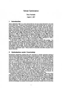
Figure 1 show the pure sliding mode controller applied to continuum robot.
Figure 1. Sliding Mode Controller Fuzzy Logic Control: Fuzzy-logic aims to provide an approximate but effective means of describing the behavior of systems that are not easy to describe precisely, and which are complex or ill-defined. It is based on the assumption that, in contrast to Boolean logic, a statement can be
24
International Journal of Control and Automation Vol. 6, No. 3, June, 2013
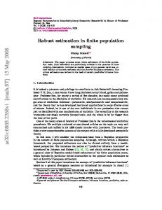
partially true (or false). For example, the expression (I live near IAU) where the fuzzy value (near) applied to the fuzzy variable (distance), in addition to being imprecise, is subject to interpretation. The essence of fuzzy control is to build a model of human expert who is capable of controlling the plant without thinking in terms of its mathematical model. As opposed to conventional control approaches where the focus is on constructing a controller described by differential equations, in fuzzy control the focus is on gaining an intuitive understanding (heuristic data) of how to best control the process, and then load this data into the control system. The central idea of fuzzy sets is that elements can have partial membership in a given set. In contrast to a classical set, a fuzzy set, as the name implies, is a set without a crisp boundary. In this respect, fuzzy sets are functions that map a value to a number between zero and one, indicating its actual degree of membership. A degree of zero means that the value is not in the set, and a degree of one means that the value is completely representative of the set. They were introduced by Prof. Lotfi A. Zadeh in 1965 as an extension of the classical notion of “set” and as a mathematical way to represent and deal with vagueness in everyday life. The fuzziness does not come from the randomness of the constituent members of the set, but from the uncertainties and imprecise nature of abstract thoughts and concepts. A Fuzzy-Logic System (FLS) is a non-linear mapping from the input to the output space, where the input is first fuzzified as shown in Figure 2.
Figure 2. Implementation of Fuzzy-Logic Control System, Adapted From The fuzzy sets computed by the fuzzy inference as the output of each rule are then composed and defuzzified. Fuzzification helps in evaluating the rules, but the final output of a fuzzy system has to always be a crisp number. (i.e. conversion from a fuzzy set to a crisp number). Fuzzy membership functions on the other hand, are defined in terms of numerical values of an underlying crisp attribute. For example: Short, Medium and Tall in terms of the fuzzy variable: height. In other words, determining how much each discrete input value belongs to each input fuzzy set using the corresponding membership function. Fuzzification is the process of translating crisp input values into fuzzy linguistic values (fuzzy sets) through the use of membership functions. Generally, fuzzy membership functions are defined in terms of numerical values of an underlying crisp attribute such as short, medium and tall in terms of the fuzzy variable ‘Height’. They are subsequently processed by the inference engine that retrieves knowledge in the form of
25
International Journal of Control and Automation Vol. 6, No. 3, June, 2013
fuzzy rules contained in the knowledge-base. Fuzzy knowledge-bases is implemented as a set of IF-THEN rules as follows: • IF (condition1 AND/OR condition2) THEN (consequence). In fuzzy logic terminology, the statement following the IF is known as the premise, antecedent, or condition. The corresponding statement following THEN is known as the conclusion or consequent, and the actual calculation of the consequent using the premises calculated from the fuzzified inputs is reserved for the inference engine. In designing fuzzy systems, one should decide whether the number of rules is sufficient and if there are specific interactions between the rules. These problems were discussed in detail in the works. The inference engine is the heart of a FLC and acts as the bridge between the fuzzification and defuzzification stages. It aims at translating the designers desired control rules from a linguistic representation to a numeric computation, and can be divided into three elements: aggregation, composition, and accumulation. There are several types of FIS, which may be limited to two FIS, the most currently used, those of Takagi-Sugeno or Mamdani type, which is the FIS used in the current work. The performance of any fuzzy logic controller (FLC) is greatly dependent on its inference rules and can be drastically affected by the choice of membership functions. Thus, methods for tuning the fuzzy logic controllers are needed. Some applications considered neural networks and genetic algorithms to solve the problem of tuning a fuzzy-logic controller. In general, the system to be controlled using a FLC requires a crisp or discrete input, rather than a membership function that is produced by the inference engine. Defuzzification is the process of converting the fuzzy output set resulting from the inference process into a discrete number suitable for input to the plant. There are many different methods of defuzzification described in the literature, with varying levels of complexity. Two fundamental methods are known as the Mean of Maxima (MoM) method and the Mamdani’s Center of Gravity (CoG) method. In the current work, the Mamdani’s COG method shall be used. The discipline of intelligent control techniques is one of the most active and fruitful areas for research on advanced control systems and a number of successful applications have been reported among various fields. Fuzzy control for instance is gaining widespread acceptance in a large variety of fields, from engineering to commercial and from forecasting to artificial intelligence. The reason behind such an increasing interest resides in its flexibility and good performance in many applications where other methods either tend to fail, or become cumbersome. The foundations of Fuzzy-Logic were established by Lotfi A. Zadeh in his seminal paper on fuzzy sets, while its application in control system was pioneered by Mamdani. This latter has successfully carried out a pilot study on a model steam engine using fuzzy systems demonstrating that they may profitably and easily be used by control engineers. Since then, substantial research into fuzzy control systems has been performed. The first practical application by Mamdani and Assilian in 1975 paved the way for fuzzy control and although this alternate paradigm of control came up against much criticism it managed to capture the interest of many researchers. As such fuzzy control is now recognized as a standard, established method for controlling nonlinear systems, especially those that are complex or ill-defined and whose mathematical model is unknown or time-varying and requires human experience. However, fuzzy-logic cannot handle all types of uncertainties and is usually combined with an additional robustifying approach such as ANNs, H-infinity ( ) and Sliding Mode Control (SMC), which is a variation of variable structure control (VSS).
3. Methodology Sliding mode controller (SMC) is an important nonlinear controller in a partly uncertain dynamic system’s parameters. This controller is used in several applications such as in robotics, process control, aerospace and power electronics. Sliding mode controller is used to control of
26
International Journal of Control and Automation Vol. 6, No. 3, June, 2013
nonlinear dynamic systems particularly for robot manipulators, because it has a suitable control performance and it is a robust and stable. Conversely pure sliding mode controller is a highquality nonlinear controller; it has two important problems; chattering phenomenon and nonlinear equivalent dynamic formulation in uncertain dynamic parameter. To reduce the chattering phenomenon and equivalent dynamic problems, this research is focused on applied parallel fuzzy logic theorem in sliding mode controller as a compensator. Fuzzy logic theory is used in parallel with sliding mode controller to compensate the limited uncertainty in system’s dynamic. In this method fuzzy logic theorem is applied to sliding mode controller to remove the nonlinear uncertainty part which it is based on nonlinear dynamic formulation. To achieve this goal, the dynamic equivalent part of pure sliding mode controller is modeled by Mamdani’s performance/ error-based fuzzy logic methodology. Another researcher’s method is based on applied fuzzy logic theorem in sliding mode controller to design a fuzzy model-based controller. This technique was employed to obtain the desired control behavior with a number of information about dynamic model of system and a fuzzy switching control was applied to reinforce system performance. Reduce or eliminate the chattering phenomenon and reduce the error are played important role, therefore switching method is used beside the artificial intelligence part to solve the chattering problem with respect to reduce the error. Equivalent part of sliding mode controller is based on nonlinear dynamic formulations of robot manipulator. Robot manipulator’s dynamic formulations are highly nonlinear and some of parameters are unknown therefore design a controller based on dynamic formulation is complicated. To solve this challenge parallel fuzzy logic methodology is applied to sliding mode controller. In this method fuzzy logic method is used to compensate some dynamic formulation that they are used in equivalent part. To solve the challenge of sliding mode controller based on nonlinear dynamic formulation this research is focused on compensate the nonlinear equivalent formulation by parallel fuzzy logic controller. In this method; dynamic nonlinear equivalent part is modelled by performance/error-based fuzzy logic controller. In this method; error based Mamdani’s fuzzy inference system has considered with two inputs, one output and totally 49 rules. Figure 3 shows error-based parallel fuzzy plus sliding mode controller.
Figure 3. Parallel Optimization of Pure Sliding Mode Controller based on Fuzzy Inference Engine
27
International Journal of Control and Automation Vol. 6, No. 3, June, 2013
For both sliding mode controller and parallel fuzzy inference system plus sliding mode controller applications the system performance is sensitive to the sliding surface slope coefficient( ). For instance, if large value of is chosen the response is very fast the system is unstable and conversely, if small value of is considered the response of system is very slow but system is stable. Therefore to have a good response, compute the best value sliding surface slope coefficient is very important. In parallel fuzzy inference system compensator of sliding mode controller the PD-sliding surface is defined as follows: ̇
(39)
where
. The time derivative of S is computed; ̇ ̈
̇
(40)
Based on Figure 3, the parallel fuzzy error-based compensator of sliding mode controller’s output is written; ̂
(41)
Based on fuzzy logic methodology ( )
∑
( )
(42)
is adjustable parameter (gain updating factor) and ( ) is defined by;
where ( )
∑ ∑
( ) ( )
(43)
As mentioned in Figure 3, design an error-based parallel fuzzycompensate of equivalent part based on Mamdani’s fuzzy inference method has four steps, namely, fuzzification, fuzzy rule base and rule evaluation, aggregation of the rule output (fuzzy inference system) and defuzzification. Fuzzification: the first step in fuzzification is determine inputs and outputs which, it has two inputs ( ̇ ) and one output ( ). The inputs are error (e) which measures the difference between desired and actual output position, and the change of error ( ̇ ) which measures the difference between desired and actual velocity and output is fuzzy equivalent torque. The second step is chosen an appropriate membership function for inputs and output which, to simplicity in implementation because it is a linear function with regard to acceptable performance triangular membership function is selected in this research as shown in Figure 3.6. The third step is chosen the correct labels for each fuzzy set which, in this research namely as linguistic variable. Based on experience knowledge the linguistic variables for error (e) are; Negative Big (NB), Negative Medium (NM), Negative Small (NS), Zero (Z), Positive Small (PS), Positive Medium (PM), Positive Big (PB), and based on literature [40] and experience knowledge it is quantized into thirteen levels represented by: -1, -0.83, -0.66, -0.5, -0.33, -0.16, 0, 0.16, 0.33, 0.5, 0.66, 0.83, 1 the linguistic variables for change of error ( ̇ ) are; Fast Left (FL), Medium Left (ML), Slow Left (SL),Zero (Z), Slow Right (SR), Medium Right (MR), Fast Right (FR), and it is quantized in to thirteen levels represented by: -6, -5, -0.4, -3, -2, -1, 0, 1, 2, 3, 4, 5, 6, and the linguistic variables to find the output are; Large Left (LL), Medium Left (ML), Small Left (SL), Zero (Z), Small
28
International Journal of Control and Automation Vol. 6, No. 3, June, 2013
Right (SR), Medium Right (MR), Large Right (LR) and it is quantized in to thirteen levels represented by: -85, -70.8, -56.7, -42.5, -28.3, -14.2, 0, 14.2, 28.3, 42.5, 56.7, 70.8, 85. Fuzzy rule base and rule evaluation: the first step in rule base and evaluation is to provide a least structured method to derive the fuzzy rule base which, expert experience and control engineering knowledge is used because this method is the least structure of the other one and the researcher derivation the fuzzy rule base from the knowledge of system operate and/or the classical controller. Design the rule base of fuzzy inference system can play important role to design the best performance of parallel fuzzy plus sliding mode controller, that to calculate the fuzzy rule base the researcher is used to heuristic method which, it is based on the behavior of the control of robot manipulator. The complete rule base for this controller is shown in Table 1. Rule evaluation focuses on operation in the antecedent of the fuzzy rules in fuzzy sliding mode controller. This part is used fuzzy operation in antecedent part which operation is used. Aggregation of the rule output (Fuzzy inference): based onfuzzy methodology, Max-Min aggregation is used in this work. Table 1. Modified Fuzzy Rule Base Table
Defuzzification: The last step to design fuzzy inference in our parallel fuzzy compensator plus sliding mode controller is defuzzification. This part is used to transform fuzzy set to crisp set, therefore the input for defuzzification is the aggregate output and the output of it is a crisp number. Based on fuzzy methodology Center of gravity method ( ) is used in this research. Table 2 shows the lookup table in parallel fuzzy compensator sliding mode controller which is computed by COG defuzzification method. Table 2 has 169 cells to shows the error-based fuzzy compensate of equivalent part behavior.
4. Results and Discussion In this section, we use a benchmark model, robot manipulator, to evaluate our control algorithms. We compare the following managements: pure sliding mode controller and parallel fuzzy inference compensator plus sliding mode controller with application to continuum robot which is proposed method in this paper. The simulation was implemented in MATLAB/SIMULINK environment.
29
International Journal of Control and Automation Vol. 6, No. 3, June, 2013
Close loop response of continuum robot manipulator trajectory planning: Figures 4 and 5 illustrates the tracking performance in two types of controllers.
Figure 4. Pure SMC and Proposed Method SIN Trajectory Following and Error without Disturbance Table 2.
Performance: Lookup Table in Parallel Fuzzy Compensate of Sliding Mode Controller by COG
Based on Figure 4 and 5; pure SMC controller has error in all links, because robot is a highly nonlinear system and control of this system by pure nonlinear method is very difficult. Based on
30
International Journal of Control and Automation Vol. 6, No. 3, June, 2013
above graph, however SMC controller is a chattering free, but it has a boundary steady state error to control of this plant.
Figure 5. Pure SMC and Proposed Method ZERO Trajectory Following and Error without Disturbance
Figure 6. Pure SMC and Proposed Method ZERO Trajectory Following with Disturbance
31
International Journal of Control and Automation Vol. 6, No. 3, June, 2013
Close loop response of trajectory planning in presence of disturbance: Figure 6 demonstrates the power disturbance elimination in two types of controller in presence of disturbance for continuum robot manipulator. The disturbance rejection is used to test the robustness comparisons of these two methodologies. Based on Figure 6; by comparison with the pure SMC and proposed methodology, it can seen that proposed method is more stable and robust and this method is work based in chattering free methodology.
5. Conclusion Based on the dynamic formulation of continuum robot arm it is clear that; this system is highly nonlinear and uncertain dynamic parameters. Control of this system based on classical methodology is very complicated. The main contributions of this paper are compensating the nonlinear model base controller by nonlinear artificial intelligence model-free compensator. The structure of sliding mode controller with parallel fuzzy inference compensator is new. We propose parallel structure and chattering free compensator: parallel compensation, and chattering free method. The key technique is dead-zone. The stability analysis of parallel fuzzy compensator plus sliding mode controller is test via Lyapunov methodology. The benefits of the proposed method; the chattering effects of parallel fuzzy inference compensator plus sliding mode controller, the slow convergence of the fuzzy and the chattering problem of sliding mode method are avoided effectively.
Acknowledgment The authors would like to thank the anonymous reviewers for their careful reading of this paper and for their helpful comments. This work was supported by the SSP Research and Development Corporation Program of Iran under grant no. 2012-Persian Gulf-4D.
References G. Robinson and J. Davies, “Continuum robots–a state of the art”, Proc. IEEE International Conference on Robotics and Automation, Detroit, MI, vol. 4, (1999), pp. 2849-2854. [2] I. D. Walker, D. Dawson, T. Flash, F. Grasso, R. Hanlon, B. Hochner, W. M. Kier, C. Pagano,C. D. Rahn and Q. Zhang, “Continuum Robot Arms Inspired by Cephalopods”, Proceedings SPIE Conference on Unmanned Ground Vehicle Technology VII, Orlando, FL, (2005), pp. 303-314. [3] K. Suzumori, S. Iikura and H. Tanaka, “Development of Flexible Microactuator and it’s Applications to Robotic Mechanisms”, Proceedings IEEE International Conference on Robotics and Automation, Sacramento, California, (1991), pp. 1622-1627. [4] D. Trivedi, C. D. Rahn, W. M. Kier and I. D. Walker, “Soft Robotics: Biological Inspiration, State of the Art, and Future Research”, Applied Bionics and Biomechanics, vol. 5, no. 2, (2008), pp. 99-117. [5] W. McMahan, M. Pritts, V. Chitrakaran, D. Dienno, M. Grissom, B. Jones, M. Csencsits, C. D. Rahn, D. Dawson, and I. D. Walker, “Field Trials and Testing of “OCTARM” Continuum Robots”, Proc. IEEE International Conference on Robotics and Automation, (2006), pp. 2336-2341. [6] W. McMahan and I. D. Walker, “Octopus-Inspired Grasp Synergies for Continuum Manipulators”, Proc. IEEE International Conference on Robotics and Biomimetics, (2009), pp. 945-950. [7] I. Boiko, L. Fridman, A. Pisano and E. Usai, “Analysis of chattering in systems with second-order sliding modes”, IEEE Transactions on Automatic Control, vol. 52, no. 11, (2007), pp. 2085-2102. [8] J. Wang, A. Rad and P. Chan, “Indirect adaptive fuzzy sliding mode control: Part I: fuzzy switching”, Fuzzy Sets and Systems, vol. 122, no. 1, (2001), pp. 21-30. [9] J. J. E. Slotine, “Sliding controller design for non-linear systems”, International Journal of Control, vol. 40, no. 2, (1984), pp. 421-434. [10] R. Palm, “Sliding mode fuzzy control”, IEEE conference proceeding,(2002), pp. 519-526. [11] H. Elmali and N. Olgac, “Implementation of sliding mode control with perturbation estimation (SMCPE)”, Control Systems Technology, IEEE Transactions on, vol. 4, no. 1, (2002), pp. 79-85. [12] J. Moura and N. Olgac, “A comparative study on simulations vs. experiments of SMCPE”, IEEE conference proceeding, (2002), pp. 996-1000. [1]
32
International Journal of Control and Automation Vol. 6, No. 3, June, 2013
[13] Y. Li and Q. Xu, “Adaptive Sliding Mode Control With Perturbation Estimation and PID Sliding Surface for Motion Tracking of a Piezo-Driven Micromanipulator”, Control Systems Technology, IEEE Transactions on, vol. 18, no. 4, (2010), pp. 798-810. [14] F. Piltan, M. Akbari, M. Piran and M. Bazregar, “Design Model Free Switching Gain Scheduling Baseline Controller with Application to Automotive Engine”, International Journal of Information Technology and Computer Science, vol. 1, (2013), pp. 65-73. [15] F. Piltan, N. Sulaiman, Z. Tajpaykar, P. Ferdosali and M. Rashidi, “Design Artificial Nonlinear Robust Controller Based on CTLC and FSMC with Tunable Gain”, International Journal of Robotic and Automation, vol. 2, no. 3, (2011), pp. 205-220. [16] F. Piltan, N. Sulaiman, P. Ferdosali, M. Rashidi and Z. Tajpeikar, “Adaptive MIMO Fuzzy Compensate Fuzzy Sliding Mode Algorithm: Applied to Second Order Nonlinear System”, International Journal of Engineering, vol. 5, no. 5, (2011), pp. 380-398. [17] F. Piltan, N. Sulaiman, H. Nasiri, S. Allahdadi and M. A. Bairami, “Novel Robot Manipulator Adaptive Artificial Control: Design a Novel SISO Adaptive Fuzzy Sliding Algorithm Inverse Dynamic Like Method”, International Journal of Engineering, vol. 5, no. 5, (2011), pp. 399-418. [18] F. Piltan, N. Sulaiman, S. Allahdadi, M. Dialame and A. Zare, “Position Control of Robot Manipulator: Design a Novel SISO Adaptive Sliding Mode Fuzzy PD Fuzzy Sliding Mode Control”, International Journal of Artificial intelligence and Expert System, vol. 2, no. 5, (2011), pp. 208-228. [19] F. Piltan, S. H. Tayebi Haghighi, N. Sulaiman, I. Nazari and S. Siamak, “Artificial Control of PUMA Robot Manipulator: A-Review of Fuzzy Inference Engine And Application to Classical Controller”, International Journal of Robotics and Automation, vol. 2, no. 5, (2011), pp. 401-425. [20] F. Piltan, N. Sulaiman, A. Zare, S. Allahdadi and M. Dialame, “Design Adaptive Fuzzy Inference Sliding Mode Algorithm: Applied to Robot Arm”, International Journal of Robotics and Automation, vol. 2, no. 5, (2011), pp. 283-297. [21] F. Piltan, A. Jalali, N. Sulaiman, A. Gavahian and S. Siamak, “Novel Artificial Control of Nonlinear Uncertain System: Design a Novel Modified PSO SISO Lyapunov Based Fuzzy Sliding Mode Algorithm”, International Journal of Robotics and Automation, vol. 2, no. 5, (2011), pp. 298-316. [22] F. Piltan, N. Sulaiman, A. Jalali and K. Aslansefat, “Evolutionary Design of Mathematical tunable FPGA Based MIMO Fuzzy Estimator Sliding Mode Based Lyapunov Algorithm: Applied to Robot Manipulator”, International Journal of Robotics and Automation, vol. 2, no. 5, (2011), pp. 317-343. [23] F. Piltan, N. Sulaiman, S. Soltani, M. H. Marhaban and R. Ramli, “An Adaptive sliding surface slope adjustment in PD Sliding Mode Fuzzy Control for Robot Manipulator”, International Journal of Control and Automation, vol. 4, no. 3, (2011), pp. 65-76. [24] F. Piltan, N. Sulaiman, M. Rashidi, Z. Tajpaikar and P. Ferdosali, “Design and Implementation of Sliding Mode Algorithm: Applied to Robot Manipulator-A Review”, International Journal of Robotics and Automation, vol. 2, no. 5, (2011), pp. 265-282. [25] F. Piltan, N. Sulaiman, A. Gavahian, S. Roosta and S. Soltani, “On line Tuning Premise and Consequence FIS: Design Fuzzy Adaptive Fuzzy Sliding Mode Controller Based on Lyaponuv Theory”, International Journal of Robotics and Automation, vol. 2, no. 5, (2011), pp. 381-400. [26] F. Piltan, N. Sulaiman, S. Roosta, A. Gavahian and S. Soltani, “Artificial Chattering Free on-line Fuzzy Sliding Mode Algorithm for Uncertain System: Applied in Robot Manipulator”, International Journal of Engineering, vol. 5, no. 5, (2011), pp. 360-379. [27] F. Piltan, B. Boroomand, A. Jahed and H. Rezaie, “Performance-Based Adaptive Gradient Descent Optimal Coefficient Fuzzy Sliding Mode Methodology”, International Journal of Intelligent Systems and Applications, vol. 11, (2012), pp. 40-52. [28] F. Piltan, M. A. Dialame, A. Zare and A. Badri, “Design Novel Lookup table changed Auto Tuning FSMC: Applied to Robot Manipulator”, International Journal of Engineering, vol. 6, no. 1, (2012), pp. 25-40. [29] F. Piltan, B. Boroomand, A. Jahed and H. Rezaie, “Methodology of Mathematical Error-Based Tuning Sliding Mode Controller”, International Journal of Engineering, vol. 6, no. 2, (2012), pp. 96-112. [30] F. Piltan, F. Aghayari, M. R. Rashidian and M. Shamsodini, “A New Estimate Sliding Mode Fuzzy Controller for Robotic Manipulator”, International Journal of Robotics and Automation, vol. 3, no. 1, (2012), pp. 45-58. [31] F. Piltan, A. Jahed, H. Rezaie and B. Boroomand, “Methodology of Robust Linear On-line High Speed Tuning for Stable Sliding Mode Controller: Applied to Nonlinear System”, International Journal of Control and Automation, vol. 5, no. 3, (2012), pp. 217-236. [32] F. Piltan, A. Hosainpour, E. Mazlomian, M. Shamsodini and M. H Yarmahmoudi, “Online Tuning Chattering Free Sliding Mode Fuzzy Control Design: Lyapunov Approach”, International Journal of Robotics and Automation, vol. 3, no. 3, (2012), pp. 77-105. [33] F. Piltan, S. Emamzadeh, Z. Hivand, F. Shahriyari and M. Mirazaei, “PUMA-560 Robot Manipulator Position Sliding Mode Control Methods Using MATLAB/SIMULINK and Their Integration into Graduate/Undergraduate Nonlinear Control, Robotics and MATLAB Courses”, International Journal of Robotics and Automation, vol. 3, no. 3, (2012), pp. 106-150.
33
International Journal of Control and Automation Vol. 6, No. 3, June, 2013
[34] F. Piltan, J. Meigolinedjad, S. Mehrara and S. Rahmdel, “Evaluation Performance of 2nd Order Nonlinear System: Baseline Control Tunable Gain Sliding Mode Methodology”, International Journal of Robotics and Automation, vol. 3, no. 3, (2012), pp. 192-211. [35] F. Piltan, M. Piran, M. Bazregar and M. Akbari, “Design High Impact Fuzzy Baseline Variable Structure Methodology to Artificial Adjust Fuel Ratio”, International Journal of Intelligent Systems and Applications (IJISA), vol. 5, no. 2, (2013), pp. 59-70.
Author Mohammad Mahdi Ebrahimi is an electrical communication researcher of research and development company SSP. Co. His main areas of research interests are nonlinear control, artificial control system and robotics.
Farzin Piltan was born on 1975, Shiraz, Iran. In 2004 he is jointed the research and development company, SSP Co, Shiraz, Iran. In addition to 7 textbooks, Farzin Piltan is the main author of more than 70 scientific papers in refereed journals. He is editorial board of international journal of control and automation (IJCA), editorial board of International Journal of Intelligent System and Applications (IJISA), editorial board of IAES international journal of robotics and automation, editorial board of International Journal of Reconfigurable and Embedded Systems and reviewer of (CSC) international journal of robotics and automation. His main areas of research interests are nonlinear control, artificial control system and applied to FPGA, robotics and artificial nonlinear control and IC engine modelling and control.
Mansour Bazregar is an industrial management researcher of research and development company SSP. Co. He is now pursuing his Master in industrial management. He is an expert Industrial and Quality Management in this company. His research activities deal with the IC engine control, robot control and supply chain management.
AliReza Nabaee is an electrical electronic researcher of research and development company SSP. Co. His main areas of research interests are nonlinear control, artificial control system and robotics.
34