management for a generic vehicle power system that has multiple power sources ... simulation software as indicated in reference [22] and is used to dynamically ...
Intelligent Vehicle Power Management using Machine Learning and Fuzzy Logic ZhiHang Chen, M. Abul Masrur, and Yi L. Murphey
Abstract— We present our research in optimal power management for a generic vehicle power system that has multiple power sources using machine learning and fuzzy logic. A machine learning algorithm, LOPPS, has been developed to learn about optimal power source combinations with respect to minimum power loss for all possible load requests and various system power states. The results generated by the LOPPS are used to build a fuzzy power controller (FPC). FPC is integrated into a simulation program implemented by using a generic simulation software as indicated in reference [22] and is used to dynamically allocate optimal power sources during online drive. The simulation results generated by FPC show that the proposed machine learning algorithm combined with fuzzy logic is a promising technology for vehicle power management.
I. INTRODUCTION ROWING environmental concerns coupled with the complex issue of global crude oil supplies drive automobile industry towards the development of fuel-efficient vehicles. Advanced diesel engines, fuel cells, and hybrid powertrains have been actively studied as promising technologies for future ground vehicles because of their potential to significantly improve fuel economy and reduce emissions of ground vehicles. Due to the nature of multiple power sources, and the complex configuration and operation modes, the control strategy of a hybrid vehicle is more complicated than that of a conventional vehicle. This leads to an increasing research activities in vehicle power management. Most of the vehicle power management approaches were developed based on mathematical models or human expertise, or knowledge derived from simulation data [1, 2, 3, 4, 5, 6, 7]. The application of optimal control theory to power distribution and management has been the most popular approach, which includes linear programming [8], optimal control [9, 10, 11], and especially dynamic programming (DP) have been widely studied and applied to a broad range of vehicle models [10, 2, 12, 1, 13]. In general, these techniques do not offer an on-line solution, because they assume that the future drive cycle is entirely known. More recently various intelligent systems approaches such as neural networks, fuzzy
G
logic, genetic algorithms, etc. have been applied to vehicle power management [7, 14, 15, 16, 17, 18, 19] with attempts for online intelligent power control. A comprehensive overview of intelligent systems approaches in vehicle power management can be found in [20]. In this paper we present our research in the area of minimizing power loss in a multi-power-source HEV system with applications to heavy duty vehicles: military vehicles, construction and utility industry vehicles (for example garbage trucks) where the load demand can fluctuate significantly and also be of intermittent nature. We present a methodology that uses machine learning to find optimal combinations of the energy/power sources for a given load request, which leads to a fuzzy power controller that gives optimal energy efficiency while satisfying system and component constraints. Our research is built on a vehicle architecture of multi-power-sources and multi-loads. Specifically, we focus on the following four commonly seen power sources in vehicle power systems: alternator, fuel cell, ultracapacitor, and battery. Both the machine learning algorithm and the fuzzy controller are fully implemented. The machine learning algorithm, LOPPS (Learning OPtimal Power Sources), learns from simulation data about the optimal power source combinations for a broad range of possible power requests with constraints related to the State Of Charge (SOC) of power sources such as batteries and ultracapacitors and the system voltage. Based on the results of LOPPS, a fuzzy power controller (FPC) is developed for allocating optimal power sources during an online drive cycle. Based on our experiments conducted on two types of drive cycles, one simulates heavy and frequent load requests, and the other the lower and few load requests. This paper is organized as follows. Section II presents the multi-power-source vehicle power system architecture and definition of the power management problem in this vehicle power system. Section III introduces the machine learning algorithm, LOPPS, Section IV presents the fuzzy power controller FPC for online optimal power allocation, Section V presents our experiment results and Section VI concludes the paper. II. A MULTI-POWER SOURCE AND MULTI-LOAD VEHICLE POWER
This work was supported in part by a research contract from the US Army RDECOM-TARDEC. ZhiHang Chen and Yi L. Murphey are with the Department of Electrical and Computer Engineering at the University of Michigan-Dearborn, Dearborn, MI 48128, USA (Phone: 313-593-5028; fax: 313-583-6336; e-mail: yilu@ umich.edu). M. Abul Masrur is with US Army RDECOM-TARDEC.
SYSTEM
We are interested in vehicles that have multiple power sources and have load requests fluctuate through a drive cycle. Mathematically we formulate the power management problem as follows. Let V denote a vehicle power system, V has n
Form Approved OMB No. 0704-0188
Report Documentation Page
Public reporting burden for the collection of information is estimated to average 1 hour per response, including the time for reviewing instructions, searching existing data sources, gathering and maintaining the data needed, and completing and reviewing the collection of information. Send comments regarding this burden estimate or any other aspect of this collection of information, including suggestions for reducing this burden, to Washington Headquarters Services, Directorate for Information Operations and Reports, 1215 Jefferson Davis Highway, Suite 1204, Arlington VA 22202-4302. Respondents should be aware that notwithstanding any other provision of law, no person shall be subject to a penalty for failing to comply with a collection of information if it does not display a currently valid OMB control number.
1. REPORT DATE
2. REPORT TYPE
06 MAR 2008
N/A
3. DATES COVERED
-
4. TITLE AND SUBTITLE
5a. CONTRACT NUMBER
Intelligent Vehicle Power Management using Machine Learning and Fuzzy Logic
5b. GRANT NUMBER 5c. PROGRAM ELEMENT NUMBER
6. AUTHOR(S)
5d. PROJECT NUMBER
Chen, ZhiHang; Masrur, Abul M; Murphey, Yi L
5e. TASK NUMBER 5f. WORK UNIT NUMBER
7. PERFORMING ORGANIZATION NAME(S) AND ADDRESS(ES)
US Army RDECOM-TARDEC 6501 E 11 Mile Rd Warren, MI 48397-500 9. SPONSORING/MONITORING AGENCY NAME(S) AND ADDRESS(ES)
8. PERFORMING ORGANIZATION REPORT NUMBER
#18693 10. SPONSOR/MONITOR’S ACRONYM(S)
TACOM/TARDEC 11. SPONSOR/MONITOR’S REPORT NUMBER(S)
#18693 12. DISTRIBUTION/AVAILABILITY STATEMENT
Approved for public release, distribution unlimited 13. SUPPLEMENTARY NOTES
Presented at the World Congress on Computational Intelligence (WCCI 2008), June 1-6, 2008, Hong Kong, The original document contains color images. 14. ABSTRACT
Abstract We present our research in optimal power management for a generic vehicle power system that has multiple power sources using machine learning and fuzzy logic. A machine learning algorithm, LOPPS, has been developed to learn about optimal power source combinations with respect to minimum power loss for all possible load requests and various system power states. The results generated by the LOPPS are used to build a fuzzy power controller (FPC). FPC is integrated into a simulation program implemented by using a generic simulation software as indicated in reference [22] and is used to dynamically allocate optimal power sources during online drive. The simulation results generated by FPC show that the proposed machine learning algorithm combined with fuzzy logic is a promising technology for vehicle power management. 15. SUBJECT TERMS 16. SECURITY CLASSIFICATION OF: a. REPORT
b. ABSTRACT
c. THIS PAGE
unclassified
unclassified
unclassified
17. LIMITATION OF ABSTRACT
18. NUMBER OF PAGES
SAR
8
19a. NAME OF RESPONSIBLE PERSON
Standard Form 298 (Rev. 8-98) Prescribed by ANSI Std Z39-18
different power sources, P_S = {P1, P2, …, Pn}, L different load requests at all time, L_R = { l 1 ,..., l L }. We define a drive cycle as a sequence of load requests DC = {LR(t) | t ∈ [0, te]}, where t=te is the ending time of the drive cycle and LR(t) ∈ L_R. We attempt to develop an intelligent power management system, F, that makes an intelligent decision at
time t what power sources are to be allocated, i.e. F (C1, …, Cn, LR(t), V_S(t)) = {Pi1, Pi2, …, Pik} ⊆ { P1, P2, …, Pn}, for a given request of loads, LR(t), current vehicle power system state, V_S(t), and the cost function Ci associated with each power source Pi and the cost of power consumption for power sources {Pi1, Pi2, …, Pik} is minimum.
Vbus 42volts
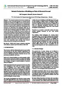
Figure 1. The schematic diagram of a multiple power sources and multiple loads system
Figure 1. shows the architecture of a vehicular power system architecture used in this research. A voltage bus is used in the vehicle power system, which can be a 42-volt system, to connect the power sources to the electric loads. The vehicle power system has four power sources, an alternator (Alt), fuel cell (FC), an ultracapacitor (Ucap), and a battery(Bat). In a conventional vehicle, the alternator is directly coupled to the engine’s crankshaft and can be used to charge the battery or ultracapacitor, thus help maintain a fixed voltage level on the power net. In an HEV, the alternator is referred to as a generator. So, controlling its output power will influence the operating point of the combustion engine, and thus the fuel use of the vehicle. The most popular fuel cell for vehicles is an electrochemical device that combines hydrogen and oxygen to produce electricity, with water and heat as its by-product. As long as fuel is supplied, the fuel cell will continue to generate power. Since the conversion of the fuel to energy takes place via an electrochemical process, not combustion, the process is clean, quiet and highly efficient – two to three times more efficient than fuel burning. Research in HEV trucks has been focused on
using a fuel cell as the primary energy source, a battery and/or flywheel to store energy, one or more motor–generators to drive the vehicle, and an inverter–power distribution system to control the power flow between the fuel cell, flywheel, and motor–generators[21]. A traditional lead-acid battery has been present in vehicles for supplying key-off loads and, sometimes, continuous load requirements when the alternator itself may not be used efficiently[13]. Ultra-capacitors are energy storage devices. They use electrolytes and configure various-sized cells into modules to meet the power, energy, and voltage requirements for a wide range of applications. But batteries store charges chemically, whereas ultracapacitors store them electrostatically. Although, ultracapacitors are more expensive (per energy unit) than batteries, they have a much greater instantaneous power capability compared to batteries of similar physical size. An ultracapacitor can receive regenerative energy and give power during peak periods. Moreno et al. proposed to use an ultracapacitor as an auxiliary energy system in combination with a primary source that is unable to accept energy from the regenerative braking[22]. There are other power sources that are being
considered in HEV research [20-22] and future vehicle systems may use combinations of these power sources shown in Figure 1 or beyond. In this research the following assumptions are made: • The power sources and the loads are connected through on/off switches. • The total load request P is delivered by m selected power sources, each delivers P/m to the voltage bus. • We assume that each power source is associated with a cost function of power drawn from the power source, which is measured as power loss defined as follows: o
k Ploss = Pgk − Prk , where Prk , Pgk ,
and
k loss
P
are the power requested,
power generated and power loss from the kth power source.
5
x 10 3
alt bat fc uc
2.5
2
1.5
1
0.5
0 0
0.5
For m power sources there are Κ possible power source combinations that can be used to deliver a power to a load request LR(t):
Κ=
n
n
n
i =1
i =1
1.5
2
2.5
3
3.5
4
4.5 4
x 10
(a) Accumulative power losses of five different power sources during a drive cycle 45
40
35
30
25 alt bat fc uc
20
III. MACHINE LEARNING OF LOAD BASED POWER LOSS
1
15 0
0.5
1
1.5
2
2.5
3
3.5
4
4.5 4
x 10
(b) System bus voltage function during the simulations during which each of the five power source is used.
n!
∑ i = ∑ i!(n − i)! .
The objective function for minimizing power loss is defined as follows: te
te
t =0
t =0
Min ∑ Power _ Loss(t ) = ∑ Min Power _ Loss(t ) PS
PS ( t )
te
= ∑ Min PL( LR(t ),V _ S (t )) t =0
PS ( LR ( t ))
where PL is the power lost function, V_S(t) is vehicle power system state at time t, PS is the power source combination function, and LR is the load request made at time t in a drive cycle which runs from t=0 to t = te. For each power source combination at time t, PS(t) {Pt1, Pt2, …, Ptk} ⊆ { P1, P2, …, Pm}, the power loss function at time t is: k
PL(LR(t), V_S(t)) =
∑P
ti loss
i =1
k
= ∑ Pgti − Prti , and i =1
k
∑P
i r
= LR(t).
i
The vehicle power system state is modeled by the State of Charge of the power sources that have functions of charge and discharge and the system voltage at the voltage bus. For the power system shown in Figure 1, V_S = { SOCUcap , SOCBat , Voltagev_bus}.
(c) System bus voltage (left) and SOCUcap when an ultracapacitor is the only power source used during this simulation. Figure 2. Analysis of power loss, bus voltage and SOC
Figure 2 shows the simulation results of power loss analysis with different power sources and SOCs and load requests. Figure 2 (a) shows the accumulative power loss curves generated by five simulations, each of which uses a different single power source: the dark blue represents the simulation in which only the alternator is used, the pink curve is when only fuel cell is used, the yellow curve is only the battery used, the light blue curve is when the ultracapacitor is used, and the maroon curve is when a hybrid power source is used in the simulation. All five simulations have the same load request of 13900 W. These power loss curves appear to indicate that the ultracapacitor has the minimum power loss. Figure 2 (b) shows the voltage at the power system bus during the simulations. It shows that the system voltage was plummeting during the simulation and ended at 25V. Figure 2 (c) shows an additional simulation in which the ultracapacitor was used alone with the simulation time extended to 300minutes with the same electric load request. The SOCUcap reached 0 at t=300minutes, and so did the system voltage. These simulation results show that different power sources have
different power loss function and power loss alone is not sufficient to measure the system performance, constraints must be placed to make sure the system provides good quality power service at the same time the power loss is minimized. Since the combinations of the multiple power sources and the loads in the architecture under consideration form a nonlinear system, it is not trivial to optimize the system using closed form equations. Hence a machine learning algorithm is developed to learn about the optimal power source combinations from simulated data. The machine learning algorithm, LOPPS, is developed based on the following assumption: • There are L different categories of electric load requests, which are denoted as L_R and a load request in a drive cycle at t LR(t) ∈ LD. Note a load request l i is a combination of the loads •
•
shown in Figure 1. There is a simulation program that simulates the system architecture shown in Figure 1 with all the power sources in P_S and loads in LD, accurately calculates the power consumption and power loss for each power source. We denote this program as MPS_ML. Let PC denote the set of power source combinations, i.e. PC = { pc1 , pc2 , …,
pcΚ } •
The following constraints should be incorporated in during system optimization o LOWERucap < SOCucap < UPPERucap, o LOWERbat < SOCbat < UPPERbat, o LOWERv_bus < Voltagev_bus < UPPERv_bus,
Algorithm of Learning OPtimal Power Sources(LOPPS) Step 1 i =0, Step 2 If i ≤ L go to Step 3 else stop
LR1
start 0
LR2
15
Step 3 t = 0, j = 0, and set the initial vehicle state: V_S(t) = { Init_SOCucap , Init_SOCBat, Init_Voltagev_bus } Step 3.1 For time interval [t, t+ ∆t ] run the simulation program MPS_ML to generate power losses for each of the Κ power source combinations for the load request l i , Step 3.2 Select the power source combination with the minimum power loss based on V_S(t) and l i denote it as pso(t). Step 3.3 Update the SOCs of ultracapacitor and the battery, SOCUcap(t+ ∆t ) and SOCBat(t+ ∆t ) based on pso(t). Step 3.4 If any components within V_S(t+ ∆t ) are out of the bounds, select the next best power combination by going back to Step 3.2. Step 3.5. Store the best power source combinations in OP_PS[i, j], where j is the index of the time intervals during the simulation of drive with a constant load request l i . Step 4. t = t+ ∆t , j=j+1 and goto Step 3.1. Step 5. i = i+1, goto Step 2. IV. A FUZZY POWER CONTROLLER A drive cycle can be defined in general terms of electric loads requested by the driver through the trip. Figure 3 illustrates the definition of a drive cycle. A drive cycle starts with a specific electric load for the starting of the vehicle, we denote it as “start”, and ends with a specific electric load, denoted as “stop,” that is used to turn off the vehicle. The amounts of power requested by “start” and “stop” are vehicle dependant but not drive cycle dependant. For the ease of description, we will ignore these two load requests, assume driver’s load requests begins at time t=0 and ends at t=te, and the time duration for these load requests are normalized to the percentage of the entire trip time te. In this example the entire drive cycle is composed of 10 different load requests, each load request is encoded using LRi, i = 1, …, 10, whose values are shown in Figure 4.
LR3 LR4 LR5 LR7 LR8 LR9
40
50
60 65 70
LR10
75 80
Figure 3. DC1: a drive cycle defined in terms of load requests.
stop 100
Time slot (%)
LR7
LR8
Figure 4. Ten load requests used in our simulation program.
Figure 5. Fuzzy membership functions for fuzzy variable SOCB
LR9
LR10
ai n
LR6
Su st
LR5
MO PP
LR4
Ma in t Fo rd in g Tr an si t Co ld Op s Pr ot ec t
LR3
en t Pl an ni ng
LR2
Si l
LR1
Co mb at
Load( W)
16000 14000 12000 10000 8000 6000 4000 2000 0
Figure 6. Examples of fuzzy rules.
start
4
0
stop
10
75
100
Time slot (%)
Figure 7. DC2: A drive cycle with low electric loads and less frequent requests
The objectives of the fuzzy power controller are as follows: o For a drive cycle, power sources should be dynamically allocated so maximum energy efficiency or minimum power loss can be achieved. o
At any time during the drive cycle, the fuzzy power controller must provide a high level vehicle performance, which is measured by delivering adequate power as soon as a load request is made and the system state must satisfy all three constraints discussed in the previous section.
These above two objectives are attained by the use of the knowledge about optimal power source combinations based on all possible load requests, OP_PS[x, y] generated by the machine learning algorithm LOPPS, where x is the variable representing load request and y is the variable represents the index of the time interval, and OP_PS[x, y] contains the optimal power source combination and the system power state as the result of using the selected power source combination at the time interval index y for the load request indexed by x. The fuzzy power controller is
designed to map the system power state at time t during a drive cycle when a new load request is made to the most suitable x’, y’, and use the best power source combination stored in OP_PS[x’, y’] to deliver power to the vehicle load request made at time t. The fuzzy power controller has fuzzy variables to represent the SOC of batteries and ultracapacitors and the load requests, l 1 , …, l L . The fuzzy membership functions can be defined based on expert knowledge. The solution variable is, y, a fuzzy variable to represent the index of the time interval whose SOCs have the best match to the current system power state. For the vehicle power system shown in Figure 1 and the 10 load requests shown in Figure 4, the fuzzy power controller has 4 fuzzy variables, SOCU and SOCB represent the SOC of the ultracapacitor and the batter respectively, Mode_a, Mode_b represent the ten load requests. The fuzzy membership functions for each fuzzy variable are generated using the fuzzy logic toolbox from commercial software [22] and 36 fuzzy rules are generated based on the optimal power source knowledge contained in OP_PS[x, y]. Figure 5 shows an example of fuzzy membership functions for SOC_u and Figure 6 shows a few examples of the fuzzy rules. When used in online control during a drive cycle, the fuzzy power controller has the following computational steps. Step 1. Let the current time during a drive cycle DC is t, and
a new load request, l , has been made by the driver. Step 2. Calculate the current vehicle power state (SOCB, SOCU), fuzzify the SOCs by mapping them to the respective fuzzy membership functions Step 3. fuzzify current load request l . Step 4. Fire the fuzzy rule that being triggered by the fuzzified SOCB, SOCU and l . Take the consequence of the fired rule, T* and extract the optimal power source combination from OP_PS[ l , T*].
3
x 10
5
All on On line Fuzzy control
2.5 2 1.5 1 0.5
V. Experiments We have implemented the vehicle power system shown in Figure 1 using commercial software tool [22] in a program called MPS_ML. The MPS_ML generated power losses for all 15 power source combinations for all 10 load requests shown in Figure 4. The machine learning algorithm, LOPPS, is implemented in Visual C++. LOPPS generated the knowledge about the optimal power source combinations for every load request at every specified time interval that satisfy all three system constraints specified as follows: LOWERucap = 40% , UPPERucap = 95%, LOWERbat = 40% , UPPERbat = 90%, LOWERv_bus = 38w, UPPERv_bus = 45w. The fuzzy rule base was generated from the data generated by LOPPS that uses a time step ∆t =10, and the entire simulation time is 100 minutes in every simulation run. The fuzzy power controller presented in Section III is implemented by using commercial software tools [22] and is fully integrated into MPS_ML to be used as online power allocation function. Two types of drive cycles are used to test the performance of the fuzzy power controller, one drive cycle simulates heavy and frequent load requests, which is shown in Figure 3, and the other the lower and few load requests, which is shown in Figure 7. We compare the performance of the fuzzy controller with the default controller, which uses all four power sources during the entire drive cycle, and an online controller that uses the If-then rules based on crispy logic. The results are shown in Figure 8.
0 0
(a)
20
40
60
80
100
Accumulative power loss during drive cycle DC1.
2.5
x 10
5
All on On line Fuzzy control
2
1.5
1
0.5
0 0
20
40
60
80
100
(b) Accumulative power loss during drive cycle DC2. Figure 8. Comparison of FPC with two other power controllers.
In both experiments, the FPC has the least power loss. In the DC1, the load request change occurred frequently and requested loads are high; in DC2, the load requests occurred only two times and the requested loads are much lower than most in DC1. The reduction of power loss in DC1 made by the fuzzy power controller is 28% in comparison with the default controller, and the online controller had the power loss reduction of 10%. For DC2, the fuzzy power controller gave 60% power loss reduction, whereas the online controller had the reduction of only 5%. VI. CONCLUSION In this paper we presented our research results in optimizing power loss in a multi-power-source and multi-load vehicle power system. A machine learning algorithm LOPPS is developed that can learn about optimal power source combinations for a given load request at various vehicle power states. A fuzzy power controller (FPC) is developed that builds its knowledge base from the results of LOPPS. When FPC is used as the online power controller, it showed a large reduction in power loss in comparison with the default all-on controller and the online controller that uses conventional crispy logic.
REFERENCES [1]
[2]
[3]
[4]
[5]
[6]
[7]
[8]
[9]
[10]
[11]
[12]
[13]
[14]
[15]
[16]
[17]
[18]
J. Arsie, M. Graziosi, C. Pianese, G. Rizzo, and M. Sorrentino, “Optimization of supervisory control strategy for parallel hybrid vehicle with provisional load estimate,” in Proc. 7th Int. Symp. Adv. Vehicle Control (AVEC), Arnhem, The Netherlands, Aug. 2004. C.-C. Lin, H. Peng, J.W. Grizzle, and J.-M. Kang, “Power management strategy for a parallel hybrid electric truck,” IEEE Trans. Contr. Syst. Technol., vol. 11, no. 6, pp. 839–849, Nov. 2003. C.-C. Lin, H. Peng, and J.W. Grizzle, “A stochastic control strategy for hybrid electric vehicles,” in Proc. Amer. Contr. Conf., Boston, MI, Jun. 2004, pp. 4710–4715. G. Paganelli, G. Ercole, A. Brahma, Y. Guezennec, and G. Rizzoni, “General supervisory control policy for the energy optimization of charge-sustaining hybrid electric vehicles,” JSAE Rev., vol. 22, no. 4, pp. 511–518, Apr. 2001. Langari, R.; Jong-Seob Won, “Intelligent energy management agent for a parallel hybrid vehicle-part I: system architecture and design of the driving situation identification process,” IEEE Transactions on Vehicular Technology, volume 54, issue 3, Page(s):925 – 934, 2005 N. J. Schouten, M. A. Salman, and N. A. Kheir, “Fuzzy logic control for parallel hybrid vehicles,” IEEE Trans. Contr. Syst. Technol., vol. 10, no. 3, pp. 460–468, May 2002. Jong-Seob Won; Langari, R., “Intelligent energy management agent for a parallel hybrid vehicle-part II: torque distribution, charge sustenance strategies, and performance results,” IEEE Transactions on Vehicular Technology, volume 54, issue 3, Page(s):935 – 953,2005. E. D. Tate and S. P. Boyd, “Finding ultimate limits of performance for hybrid electric vehicles,”, SAE Paper-01-3099, 2000. J. Bumby and I. Forster, “Optimization and control of a hybrid electric car,” Inst. Elect. Eng. Proc., pt. Part D, vol. 134, no. 6, pp. 373–387, Nov. 1987. M. Back, M. Simons, F. Kirschaum, and V. Krebs, “Predictive control of drivetrains,” in Proc. IFAC 15th Triennial World Congress, Barcelona, Spain, 2002. S. Delprat, J. Lauber, T.M. Guerra, and J. Rimaux, “Control of a parallel hybrid powertrain: optimal control,” IEEE Trans. Veh. Technol., vol. 53, no. 3, pp. 872–881, May 2004. T. Hofman and R. van Druten, “Energy analysis of hybrid vehicle powertrains,” in Proc. IEEE Int. Symp. Veh. Power Propulsion, Paris, France, Oct. 2004. Koot, M.; Kessels, J.T.B.A.; de Jager, B.; Heemels, W.P.M.H.; van den Bosch, P.P.J.; Steinbuch, M., “Energy management strategies for vehicular electric power systems,” IEEE Transactions on Vehicular Technology, Volume 54, Issue 3, Page(s):771 – 782, May 2005 V. H. Johnson, K. B.Wipke, and D. J. Rausen, “HEV control strategy for real-time optimization of fuel economy and emissions,”, SAE Paper-01-1543, 2000. J.-S. Won, R. Langari, and M. Ehsani, “Energy management strategy for a parallel hybrid vehicle,” in Proc. Int. Mechan. Eng. Congress and Exposition (IMECE ’02), New Orleans, LA, Nov. 2002, pp. IMECE2002–33 460. Sciarretta, L. Guzzella, and M. Back, “A real-time optimal control strategy for parallel hybrid vehicles with on-board estimation of the control parameters,” in Proc. IFAC Symp. Adv. Automotive Contr., Salerno, Italy, Apr. 19–23, 2004. Badreddine, B., Kuang, M. L., “Fuzzy Energy Management for Powersplit Hybrid Vehicles ” , Proc. Of Global Powertrain Conference, September 2004 Syed, F., Kuang, M. L., Czubay, J., Smith, M., Ying, H., "Fuzzy Control to Improve High-Voltage Battery Power and Engine Speed Control in a Hybrid Electric Vehicle", Soft
[19]
[20]
[21]
[22]
Computing for Real World Applications, NAFIPS, Ann Arbor, MI, June 22-25, 2005. Jorge Moreno, Micah E. Ortúzar, and Juan W. Dixon, “Energy-Management System for a Hybrid Electric Vehicle, Using Ultracapacitors and Neural Networks,” IEEE Transactions On Industrial Electronics, Vol. 53, No. 2, April 2006. Yi L. Murphey, “Intelligent Vehicle Power Management -- an overview” a chapter in the book "Computational Intelligence in Automotive Applications" to be published by Springer 2008 Richard Saeks, Chadwick J. Cox, James Neidhoefer, Paul R. Mays, and John J. Murray, “Adaptive Control of a Hybrid Electric Vehicle,” IEEE Transactions On Intelligent Transportation Systems, Vol. 3, No. 4, December 2002 Matlab Reference Manual. 2007.