MITSUBISHI ELECTRIC RESEARCH LABORATORIES http://www.merl.com
Interacting with Spatially Augmented Reality
Ramesh Raskar, Kok-Lim Low TR-2001-51
February 2002
Abstract Traditional user interfaces for off-the-desktop applications are designed to display the output on flat 2D surfaces while the input is with 2D or 3D devices. In this paper, we focus on projectorbased augmented reality applications. We describe a framework to easily incorporate the interaction on a continuum of display surfaces and input devices. We first create a 3D understanding of the relationship between the user, the projectors and the display surfaces. Then we use some new calibration and rendering techniques to create a simple procedure to effectively illuminate the surfaces. We describe various underlying techniques and discuss the results in the context of three different applications. In Proceedings of The First ACM International Conference on Virtual Reality, Computer Graphics and Visualisation in Africa (AFRIGRAPH), November 2001.
This work may not be copied or reproduced in whole or in part for any commercial purpose. Permission to copy in whole or in part without payment of fee is granted for nonprofit educational and research purposes provided that all such whole or partial copies include the following: a notice that such copying is by permission of Mitsubishi Electric Research Laboratories, Inc.; an acknowledgment of the authors and individual contributions to the work; and all applicable portions of the copyright notice. Copying, reproduction, or republishing for any other purpose shall require a license with payment of fee to Mitsubishi Electric Research Laboratories, Inc. All rights reserved. Copyright c Mitsubishi Electric Research Laboratories, Inc., 2002 201 Broadway, Cambridge, Massachusetts 02139
Submitted July 2001, revised and released September 2001.
Interacting with Spatially Augmented Reality Ramesh Raskar
Kok-Lim Low
MERL, Mitsubishi Electric Research Labs
[email protected]
University of North Carolina at Chapel Hill
[email protected]
Abstract Traditional user interfaces for off-the-desktop applications are designed to display the output on flat 2D surfaces while the input is with 2D or 3D devices. In this paper, we focus on projectorbased augmented reality applications. We describe a framework to easily incorporate the interaction on a continuum of display surfaces and input devices. We first create a 3D understanding of the relationship between the user, the projectors and the display surfaces. Then we use some new calibration and rendering techniques to create a simple procedure to effectively illuminate the surfaces. We describe various underlying techniques and discuss the results in the context of three different applications.
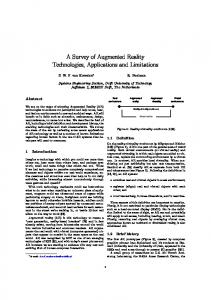
1 INTRODUCTION Recently, there has been great interest in augmented reality and tangible virtual interfaces—environments that mix the virtual and physical. There is a new trend to use light projectors to render imagery directly in our real physical surroundings. The projectors are ideal for creating life-sized images at a relatively low cost. They can be easily steered to illuminate various parts of a room. In addition, the projected images can be augmented, for example, by writing with a dry-erase marker on any illuminated whiteboard. The applications seen so far, however, typically use only a single projector. The illuminated surface is usually planar and the user location is not taken into consideration. Interaction with or modification of the displayed image is achieved using a 2D mouse or gestures limited to the plane of the displayed image. The user interface community appears to be in search of an effective 3D interface for visualization and interaction and there have been few isolated efforts to address these problems. In this paper, we present a framework to address the issue of illumination of general 3D surfaces and present 2D and 3D interaction techniques that can be easily combined within the same framework. We introduce the notion of Spatially Augmented Reality (SAR). In SAR , the user’s physical environment is augmented with images that are integrated directly in the user’s environment, not simply in their visual field. The images could appear in 2D, aligned on a flat display surface, or they could be 3D and floating above a planar or non-planar surface. In some cases, the goal is to simply change the surface attributes of the physical object. We use a combination of known techniques to store, display and transform the user interaction with the object in the digital form. Although the discussion below deals mainly with images and 3D renderings, the same techniques can be easily applied to texts, windows and icons by treating them as 3D objects. Figure 1 shows an example of illuminating a scene made up of construction styrofoam blocks to create a realistic human-sized environment.
Figure 1: (Top-left) The physical model is made of styrofoam blocks, and it approximates the geometry of the virtual environment. (Top-right) Perspectively-correct imagery of the scene is generated in real-time and projected onto the blocks. (Bottom) The user can interact with the surfaces using a virtual spray paint.
1.1
Motivation
Human interface to a physical model is the essence of ‘intuitive’. There are no widgets to manipulate, no sliders to move, and no displays to look through or wear,. Instead, we walk around objects, moving in and out to zoom, gazing and focusing on interesting components, touching or modifying using our hands or hand-held tools, all at very high visual, spatial and temporal fidelity. The digital interface to a graphics model allows many useful operations such as easy ‘undo’, recall and automation of tedious or repetitive tasks. The goal of projector-based augmentation systems is to enjoy the combined advantages of natural human interface and computer-based user interfaces. The augmentation need not be limited to whiteboards or 2D screens. The use of a projector as a display device affords us the possibility of illuminating physical objects with complex 3D shapes. This means we are inserting the result of computer graphics rendering into our physical world, instead of on a screen or a monitor. In this world-centric view of virtual objects, we have the advantage of the separation of the image displaying devices (projectors) and the display surfaces (physical objects). This leads to many interesting and useful benefits and challenges that we describe in this paper. The projectors are also getting cheaper and smaller, and images from multiple projectors can be easily combined. This makes projectors ideal for interactive AR
1.2
Previous Work
We hope to contribute to a growing body of research in ubiquitous computing, augmented reality and tangible interfaces [Ishii96].
Various levels of integration of virtual objects in the user’s physical environment are seen in current augmented reality (AR) systems [Milgram94a]. HMD-VR has been widely used to generate synthetic images inside head-tracked head-mounted displays that occlude the view of the real world but give the illusion of the spatial and temporal context in the user’s physical world. Optical and Video See-through Augmented Reality (OSTAR and VST- AR) systems combine real scene viewed by the user and a virtual scene generated by the computer to augment additional information to the view [Milgram94b] [State96]. Based on their purposes and the underlying complexity, the previous work in using projectors for augmented reality can be divided into three main groups: (i) theater and entertainment setups, (ii) projecting useful information on a planar surface, and (iii) more complex insertion of 3D shapes and attributes into the real world. The well-known and traditional examples include Naimark’s “Displacements” [Naimark84], the singing heads at Disney’s “Haunted Mansion” [Liljegren90] and Son et Lumiere shows seen on architectural monuments. These systems demonstrate the notion of explicitly separating and then later merging of the physical geometry and visual attributes of real scenes. Dorsey et al provide a useful framework in the context of theater set design [Dorsey91] where a pre-distorted image appears correct when projected onto a curved backdrop of the theater. Some systems have integrated synthetic images with real scenarios for a static user. Luminous room [UnderKoffler97] is a partially immersive spatially integrated environment, where they project and then generates 2D images on flat surfaces in a room to enhance the user’s environment. Many 2D augmentation systems are influenced by the Digital Desk project at Xerox PARC, in which, a desktop or papers on the desktop are augmented with projected synthetic images or live video images of a symmetric system [Wellner93] [Mankoff98]. Smart whiteboards are also becoming popular [Mynatt99]. Projectors are used for virtual reality and augmented reality applications where the inserted objects as well as illuminated surfaces are non-planar. The HoloGlobe exhibit uses precision optical components, such as parabolic mirrors and beam splitters, in its High Definition Volumetric Display to display huge amounts of data concerning global change on a four-foot, 3-D floating image of the Earth [Hologlobe]. Viewers can walk around the 3D image and see it from different angles. The users do not need to wear any gear. In the Office of the Future (OOTF) [Raskar98], the user is surrounded by synthetic images such as in spatially immersive displays (SID). CAVE [Cruz-Neira93] and ARC’s dome-shaped displays [Benette98] are other examples of SID. However, in OOTF the display surfaces are not limited to the designated flat walls (or parameterized surfaces), but could be everyday surfaces.
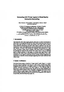
Figure 2. Geometric relationship for displaying virtual object. The user could be static or moving.
2 PROJECTOR-BASED AR We have previously seen the description of augmented reality as a new class of display along the reality-virtuality continuum [Milgram94b] [Mynatt98]. For projector-based AR, we classify the systems and problems along the other dimensions of interactive display continuum, such as the range of geometric similarity between the real and virtual objects. In this paper we discuss and describe new rendering techniques that take into account the relationships between the user position, real objects, the virtual objects, the light projectors, the location of input devices and the surface attributes of the real and virtual objects.
2.1
Consider the problem of displaying a virtual object on a potentially non-planar surface using a projector. Our goal is to present a perspectively correct image to a moving user. The relationship between the user’s location, projector parameters and shape of the display surface defines the mapping between the virtual object and the projected image. In Figure 2, we see the process of mapping each virtual point, V, to a point on the display surface, M, by intersecting the ray connecting user location to V. The corresponding pixel in projector framebuffer that illuminates point M can be found using the perspective projection parameters of the projector. The result of user interaction, such as change in geometry, geometric transformation or change in surface properties, is associated with the 3D virtual object. Given this geometric relationship, we can define practically all the projectorbased display systems and the required rendering process. It is easy to see that the general notion of projector-based augmented reality is only a subset of this bigger concept.
2.2 1.3
Contribution
Our main contribution is the development of a more general description of interactive projector-based systems. We demonstrate the ideas in the context of three example projects, which include Shader Lamps, tracked object illumination and Being There. We describe the interactive display continuum and then present techniques to make the range of systems practical.
Geometric Relationship
Interactive Display Continuum
Let us consider the variations of display configuration of Figure 2. They are shown in Figure 3. The geometric shape of display screen along the display continuum could be a complex, arbitrary and unrelated curved and non-planar surface. The surface maybe planar, could be very similar to the virtual object and sometimes identical to the virtual object. The non-planar case is used in the Office of the Future system described in more detail in [Raskar98]. The planar surfaces are commonly seen in augmented
whiteboards, CAVE or immersive workbenches. The two final cases are closer to our notion of SAR. Typically, when virtual objects are introduced in the physical surroundings, the surfaces on which the virtual objects are projected have some resemblance to the physical surfaces in terms of shape or at least proximity. But there are some deviations. This is shown by the case in which the point M on the display surface is very close to the corresponding virtual point V. An example can be doors and windows on model of a building, small virtual extensions on a physical part or tiny bumps on a virtual surface projected on a smooth physical surface. In some cases, we simply want to change the surface attributes, such as color or texture, of a physical object. (This figure also includes the situation when we are simply showing some 2D text or image on a display surface.) The 3D shape and location of the physical and virtual counterpart are identical. This indicates the situation, M=V, which we describe later as part of Shader Lamps paradigm. Next in the discussion of interactive display continuum, we consider the user motion. The user can be assumed to be at a sweet spot e.g. in IMAX theaters, or believed to be static, such as in flight simulators. The interesting case is when the user is dynamic and the location is known using some type of (head) tracking system. In some cases, we may have to deal with multiple (moving) users. The geometric component of input from the user can vary from a simple movement in projector image space, a movement on the 2D manifold of the surface of the physical object to a complex 3D motion. For traditional applications, the user may simply move the mouse of the computer generating the images for the projector. The mouse could have two or more degrees of freedom [Hinckley99][Siio95]. The image of the rendering program as well as the image of the mouse pointer are seen on the physical object. This is seen in Shader Lamps project to apply virtual paint on scaled building models using a simple 2D painting program. In a free-form interaction, the user can use an input device to directly work on the surface of the physical object. For example, in digital desk or luminous room, hand-gestures or phicons are used on top of a flat surface for 2D modifications. In this case, we can map location of input devices to projector pixels and treat this similar to a traditional desktop user interface. A more complex interaction is the ‘floating’ interface such a virtual laser pointer [Olsen01] or virtual spray gun. In this case, we need to enhance the knowledge about the 3D relationship between input devices and the other three components of the rendering system: virtual object, physical object and calibration parameters of the projector. For most setups, we allow motion of the virtual objects and user. However, nothing prevents us from dynamically changing the display surfaces! As long as we know the 3D geometric shape of the surfaces we are illuminating, we can use the relationship shown in Figure 2 to compute the correct imagery. Thus, the configuration of the illuminated (display) surface could vary from being static, to moving with a single degree of freedom (such as rotation about a fixed axis), to a rigid motion with six degrees of freedom. The surface could also be deformable. Later, we describe a tracked object illumination example for a 3D painting system, in which the display surfaces can be moved by the user. If we are projecting 2D images or images of 3D objects on the body of a patient in projector-based augmented reality, then we have to take into consideration the motion of the patient (for example, breathing) while rendering the images for such deformations. Finally, for interactive display continuum, we need to consider the surface reflectance properties of the physical as well as the virtual
Figure 3. The same rendering strategy can be used for different displays surfaces, from arbitrary and unrelated curved and non-planar surface (top-left) to traditional planar screen (top-right), be very similar to the virtual object (bottom-left) to identical to the virtual object (bottom-right). objects. The illuminated surfaces could be plain simple white diffuse or colored diffuse. They could also be textured (diffuse), specular (producing highlights) or could have isotropic or anisotropic bidirection reflectance distribution function (BRDF). A complex case may involve illuminating objects that are translucent or even transparent. The desired appearance of the virtual objects can also vary from diffuse to specular to one requiring complete BRDF description.
3 RENDERING PROCESS In order to create an illusion of the virtual objects being registered with the real objects for a static or moving user, we need to know the position of the user, the projection parameters of the display devices and the shape of the real objects in the physical environment. We can then render the virtual objects on those surfaces, using real-time techniques. The overall approach in a unified projector-based SAR system is summarized below: During pre-processing Create 3D graphics model, G, of physical object Approximately position the projector Find perspective pose, P, of the projector with respect to the physical object During run-time Get user location, U, and input device parameters Modify G’s attributes based on interaction Render G using the pose P, and user location U Modify image intensity for surface orientation Modify image intensity for overlap and occlusion cancellation
First, we need to create a 3D geometric model, G, of the display surface. This can be typically achieved using offline scanning of the involved real objects, For deformable surfaces, real-time depth extraction methods may be required. The user’s location, U, can be tracked using magnetic or optical tracking technology. The projector parameters, P, can be obtained using off-line calibration process, described below, similar to the technique used for finding internal and external parameters of a camera [Faugeras93]. Projecting images on non-planar surfaces so that they appear correct to a static user have been described in [Dorsey91] [Max91] [Jarvis97]. In [Raskar98], a real time technique to generate such images for a moving head-tracked user was introduced. The technique uses two passes of rendering. In the first pass, we render the virtual object from the user’s location. In the second pass, within our rendering program, we effectively project the result of first pass onto the geometric model of the display surface and render this scenario from the projector’s viewpoint. The resultant image appears perspectively correct when illuminated on the same display surface. The computation is accomplished in real time using projective texture mapping [Segal92] support on graphics hardware. In addition to the basic model creation and rendering techniques, we need to solve two main problems: how to efficiently align projected images with real objects and how to modify pixel intensities to create high quality seamless images. We briefly mention the two issues. The technical details of the solution can found in the additional material on the project webpage.
3.1
Image Registration
To “align” a projector, we first approximately position the projector and then adapt to its geometric relationship with respect to the physical object. That relationship is computed by finding the projector’s intrinsic parameters and the rigid transformation between the two coordinate systems. This is a classical computer vision problem [Faugeras93]. We take a set of fiducials with known 3D locations on the physical object and find the corresponding projector pixels that illuminate them. This allows us to compute a 3x4 perspective projection matrix up to scale, which is decomposed to find the internal and the external parameters of the projector. The rendering process uses the same internal and external parameters, so that the projected images are registered with the physical objects.
3.2
example, without intensity correction, surfaces normal to the incident light will appear brighter than surfaces illuminated obliquely due to the cosine fall-off. This is avoided by premultiplying the projected image with intensity weights that compensate for the surface orientation. The details are in [Raskar00].
4 PROJECTS Here, we describe three of our on-going research projects in projector-based SAR. Each of them has a different position in the interactive display continuum described earlier. The details of each project can be found at http://www.cs.unc.edu/~raskar/AFRIGRAPH/.
4.1
Shader Lamps
When we illuminate a real object with a white light, its surface reflects particular wavelengths of light. Because our perception of the surface attributes is dependent only on the spectrum of light that eventually reaches our eyes, we can shift or re-arrange items in the optical path, as long as the spectrum of light that eventually reaches our eyes is sufficiently similar. Many physical attributes can be effectively incorporated into the light source to achieve a perceptually equivalent effect on a neutral object. Even nonrealistic appearances can be realized. We can use digital light projectors and computer graphics to form shader lamps that effectively reproduce or synthesize various surface attributes, either statically, dynamically, or interactively. While the results are theoretically equivalent for only a limited class of surfaces and attributes, our experience is that they are quite realistic and compelling for a broad range of applications. The existence of an underlying physical model is arguably unusual for computer graphics, however, it is not for architects [Howard00], artists, and computer animators. In addition, various
Intensity Correction
Complete illumination of closed or a disjoint set of objects requires using multiple projectors. When multiple projectors overlap, the luminance in the overlap region may be much greater than that in regions illuminated by only one projector. Thus, in addition to geometric alignment between projected images, it is also necessary to achieve intensity normalization. Another complication is the potential fragmentation of the overlap regions in respective projector framebuffers along the depth discontinuities in the scene. In [Raskar99] we described and demonstrated an image blending technique to achieve geometric alignment and intensity normalization for creating seamless images from multiple projectors. In [Raskar00], we described a complete set of techniques to deal with occlusions and overlaps. The intensity of the rendered image is also modified to take into consideration the reflectance of the neutral surface, the local orientation and distance with respect to the projector. For
Figure 4A: An example of Shader Lamps. The top figure shows a scaled-down wooden model of the Taj Mahal. It is spray-painted white. A textured 3D model is then rendered on a computer and projected onto the physical model by a light projector. We can also augment virtual lighting effects, such as shadows, on the physical model.
Figure 4B: Simple augmentation of a scaled model The video shows painting on objects in 3D using a paint program. approaches to automatic three-dimensional fabrication are steadily becoming available, e.g. laminate object manufacturing, stereolithography, and fused deposition. It is not unreasonable to argue that three-dimensional printing and faxing are coming. One major benefit of the shader-lamp approach is that it provides a very intuitive interface between the users and the model. There are no widgets to manipulate, no sliders to move, and no displays to look through (or wear). Instead, we can walk around objects, moving in and out to zoom, gazing and focusing on interesting components, all at very high visual (with auto-stereoscopic vision), spatial, and temporal fidelity. We all have a lifetime of experience with this paradigm. There are two ways we can change the virtual surface properties of a real object. In the first demonstration, we simplify the process described at the beginning of Section 3. We setup scaled wooden and cardboard models of buildings (Figure 4B). A projector is approximately positioned and it is fed with images generated by a simple 2D paint program (Adobe Photoshop). Thus, the user interaction is with a mouse in 2D and we do not generate a 3D representation of the display setup. We perspectively warp building textures to align them manually. This creates a beautiful, rich textured tabletop city model. As seen in the video, we can use a spray paint function of the photoshop program to start overwriting the underlying textures. This effectively creates the illusion of someone applying paint to the real objects. The user can use the power of traditional computer based interface e.g. with the undo function the added paint is easily removed. The second setup, we demonstrate the idea using multiple shader lamps to animate physical objects of varying complexity—from a smooth flower vase (Figure 6) to a relatively complex model of the Taj Mahal (Figure 4A). More details can be found in [Raskar00]. We generate appropriate surface reflectance and
Figure 5: A setup for image-based illumination of the Taj Mahal model. Two projectors are used to illuminate the model. The optical head tracker is seen mounted on a tripod.
Figure 6: (Left) The underlying physical object is a white diffuse clay vase. (Middle and right) View-dependent effects, such as specular highlights, can be generated by tracking the user’s location and projecting images on the physical vase. shadow animation using the knowledge configuration of the display setup.
4.2
about
the
3D
Tracked Object Illumination
We can illuminate objects so that the surface textures appear glued to the objects even as they move. In this case, we can display updated specular highlights even for a static viewer.. For example, in showroom windows or on exhibition floors, one can show a rotating model of the product in changing colors or with different features enhanced. We also built an experimental 3D painting system. A tracked “paintbrush” was used to paint on a tracked moving object held by the user (Figure 7). The object and the paintbrush are both white and they are independently tracked by rigidly mounting a sensor on them. The object and the paintbrush are illuminated by two projectors in real time, following the user controlled motion. The run-time rendering process from Section 3 now includes a rigid transformation for physical object and graphics model. In addition, the texture maps for the graphics model are updated as the user applies new paint strokes. A consistent graphics model is used by the rendering programs for both the projectors. A proximity query is used to determine whether the paintbrush is in contact with the object. We also allow a simple interface to change the color and shape of the brush, although of course the real color (white) and shape (sphere) of the brush remains fixed. The result of the user interaction, i.e. a painted model, can be easily stored for a later use. The presence of the physical model allows natural haptic feedback. The need to attach a tracker and dynamic misregistration due to tracker latency are the two main problems.
Figure 7: A tracked “paintbrush” painting on a tracked cuboid. The tracker information allows the computer to generate the correct images to illuminate the tip of the “brush” and the cuboid by the projectors.
More details can be found in [Bandyopadhyay01].
camera. This will guide the placement during post-processing because intrinsic camera parameters are not required.
4.3
A shader-lamp-guided interactive clay modeling system would be useful as a 3D version of “connect-the-dots” to provide feedback to a modeler. For example, two synchronized projectors could successively beam images of the different parts of the intended 3D model in red and green. A correct positioning of clay will be verified by a yellow (red+green) illumination. After the shape is formed, the same shader lamps can be used to guide painting of the model, or the application of a real material with matching reflectance properties.
Being There
We have begun to explore extensions of spatially augmented reality aimed at walk-thru virtual models of human-sized environments. Instead of building an exact detailed physical replica for projection, we are using simplified versions. For example, primary structures of building interiors and mid-sized architectural objects (walls, columns, cupboards, tables, etc.), can usually be approximated with simple components (boxes, cylinders, etc.). In our preliminary experiments, we are using construction styrofoam blocks to build the physical model (Figure 1). The main architectural features that match the simplified physical model retain 3D auto-stereo, but the other details must be presented by projecting view-dependent images. Nevertheless, our experiment to simulate a building interior has convinced us that this setup can provide a stronger sense of immersion when compared to CAVETM [Cruz-Neira93], as the user is allowed to really walk around in the virtual environment. Here, the user can use a virtual spray gun to change the surface color of the walls. All the computations of intersection, surface area determination and color splatting are performed in 3D and saved with the graphics model. The local copies of the graphics model used by each projector’s rendering program are updated so the user gets a seamless consistent enhanced view. (Please see the video on the website.) There are, however, several problems. Because of large concave surfaces (e.g. corners of room), inter-reflection problem becomes more serious. Moreover, since almost all of the surfaces around the user need to be illuminated, it is now easier for the user to occlude some projectors. Strategic placement of projectors is thus more critical, and that (among other things) remains as one of the outstanding challenges. More details can be found in [Low01].
4.4
Other Applications
In the simplest form, SAR and specifically, shader lamps can be used to dynamically change the color of day-to-day objects or add temporary markings on them. For example, engineers can mark the areas of interest, like drilling locations, without affecting the physical surface. As seen in Figure 1, we can render virtual shadows on scaled models. City planners can move around such blocks and visualize global effects in 3D on a tabletop rather on their computer screen. For stage shows, we can change not just the backdrops, but also simulate seasons or aging of the objects in the scene. We can also simulate motion, by projecting changing texture onto stationary rotationally symmetric objects. Interesting non-photorealistic effects can also be generated. With simple head tracking of the viewer, we have demonstrated how a clay vase can appear to be made of metal or plastic. It is easy to render other view-dependent effects such as reflections. The concept can be extended to some larger setups. Sculptors often make clay models of large statues before they create the molds. It may be useful for them to visualize how the geometric forms they have created will look with different material or under different conditions in the context of other objects. Image-based illumination can be very effectively used in movie studios where miniature models are painstakingly built and then updated with fine details. For inserting synthetic characters into a fly-thru of a miniature set, we can project silhouette of the moving virtual character that looks perspectively correct to the tracked motion
An interactive 3D touch-probe scanning system with closed-loop verification of surface reconstruction (tessellation) could be realized by continuously projecting enhanced images of the partial reconstruction on the object being scanned. This will indicate to the person scanning the required density of points, the regions that lack samples and the current deviation of the geometric model from the underlying physical object. A useful 2-handed 3D modeling and 3D painting setup would involve tracking the user’s viewpoint, input devices and a coarsely-shaped object (such as a sphere). The user can literally create and add surface properties to a virtual object that is registered with the sphere.
5 BENEFITS AND LIMITATIONS A key benefit of SAR is that the user does not need to be constrained in front of a monitor or wear a head-mounted display. In [Bryson97] various advantages of spatially immersive displays. SAR shares similar benefits. In SAR, large field-of-view images can be generated with greater amount of integration of virtual objects with the real world. This can greatly improve the sense of immersion or the effectiveness of user interaction. Projector-based SAR allows possibly higher resolution and brighter images of virtual objects, text or fine details. Since virtual objects are typically rendered near their real-world location, eye accommodation is easier. The most crucial problem with projector-based SAR is its dependence on display surface properties. A light colored diffuse object with smooth geometry is ideal. It is practically impossible to render vivid images on highly specular, low reflectance or dark surfaces. The ambient lighting can also affect the contrast of the images. This limits the application of SAR to controlled lighting environments with restrictions on the type of objects with which virtual objects will be registered. For front-projector-based SAR, shadows of the user can create problems. This can be partially overcome using multiple projectors. SAR, when displaying floating virtual objects, allows only one active head-tracked user at any instant in the environment because the images are created in the physical environment rather than in individual user’s space. Time multiplexed shuttered glasses can be used to add more users that are active and head- tracked.
6 CONCLUSION Projector-based spatially augmented reality systems combine the best of both: simplicity of natural interface and power of computational resources. The resulting interface is easy to use and visual images are very compelling. Best of all, they can be used by anyone with minimal training. Others have certainly used light projectors and even LCD panels to add virtual imagery to real environments. However, this is essentially an augmented reality
problem, albeit an unusual one. We have presented a rendering process for image generation and interaction for a continuum of interactive display configurations and described various demonstrations. We hope the techniques are used for a variety of applications including training, architectural design, art and entertainment. Please see high resolution images, related papers and video clips at http://www.cs.unc.edu/~raskar/AFRIGRAPH/
7 REFERENCES [Azuma94] Azuma, R., Bishop, G. Improving Static and Dynamic Registration in an Optical See-through HMD. Proceedings of SIGGRAPH 94 (Orlando, Florida, July 24-29, 1994). In Computer Graphics Proceedings, Annual Conference Series, 1994, ACM SIGGRAPH, pp. 197-204. [Bandyopadhyay01] D Bandyopadhyay, R Raskar, A State, H Fuchs, Dynamic Spatially Augmented 3D Painting. UNC Chapel Hill Tech Report TR01-006, 2001. [Bennett98] David T. Bennett. Chairman and Co-Founder of Alternate Realities Corporation, 215 Southport Drive Suite 1300, Morrisville, NC 27560, USA. [Bryson97] Bryson, Steve, David Zeltzer, Mark T. Bolas, Bertrand de La Chapelle, and David Bennett. The Future of Virtual Reality: Head Mounted Displays Versus Spatially Immersive Displays, SIGGRAPH 97 (Panel) Conference Proceedings, Annual Conference Series, ACM SIGGRAPH, Addison-Wesley, pp. 485-486, August 1997. [Cruz-Neira93] Carolina Cruz-Neira, Daniel J. Sandin, and Thomas A. DeFanti. 1993. Surround-Screen Projection-Based Virtual Reality: The Design and Implementation of the CAVE, SIGGRAPH 93 Conference Proceedings, Annual Conference Series, ACM SIGGRAPH, Addison Wesley. [Dorsey91] Julie O’B. Dorsey, Francois X. Sillion, Donald P. Greenberg. 1991. ÒDesign and Simulation of Opera Lighting and Projection Effects,Ó SIGGRAPH 91 Conference Proceedings, Annual Conference Series, Addison-Wesley, pp 41-50. [Faugeras93] O. Faugeras. Three-Dimensional Computer Vision: A Geometric Viewpoint. MIT Press, Cambridge, Massachusetts, 1993. [Hinckley99] Hinckley, K., Sinclair, M., Hanson, E., Szeliski, R., Conway, M. The VideoMouse: A Camera-Based MultiDegree-of-Freedom Input Device. ACM UIST'99 Symposium on User Interface Software & Technology, pp. 103-112 [Holloway95] Holloway, R. Registration Errors in Augmented Reality Systems, PhD Thesis. University of North Carolina at Chapel Hill, 1995. [Hologlobe] (Cited July 10, 1998) http://www.3dmedia.com [Howard00] HowardModels.com, 7944 Central Avenue, Toledo, OH 43617. http://www.howardweb.com/model/ [Ishii96] Ishii, Hiroshi & Ulmer, B. Tangible Bits: Towards seamless interfaces between people, bits and atoms. Proceedings of CHI’96. New York: ACM. [Jarvis97] Kevin Jarvis, Real Time 60Hz Distortion Correction on a Silicon Graphics IG, in Real Time Graphics, Vol. 5, No. 7, pp. 6-7, February 1997. [Liljegren90] G. E. Liljegren and E. L. Foster. Figure with Back Projected Image Using Fiber Optics. US Patent # 4,978.216, Walt Disney Company, USA, December 1990.
[Low01] K. Low, G. Welch, A. Lastra, H. Fuchs. Life-Sized ProjectorBased Dioramas: Spatially Real and Visually Virtual. To appear in Sketches & Applications, SIGGRAPH 2001. [Mankoff98] Jennifer, Jonathan Somers and Gregory D. Abowd. "Bringing People and Places Together with Dual Augmentation.” Collaborative Virtual Environments, Manchester. June 1998. [Max91] Nelson Max. 1991. "Computer animation of photosynthesis," Proceedings of the Second Eurographics Workshop on Animation and Simulation, Vienna, pp. 25-39. [Milgram94a] P Milgram and F Kishino. "A taxonomy of mixed reality visual displays", IEICE (Institute of Electronics, Information and Communication Engineers) Transactions on Information and Systems, Special issue on Networked Reality, Dec. [Milgram94b] P Milgram, H Takemura, A Utsumi and F Kishino. "Augmented Reality: A class of displays on the realityvirtuality continuum". SPIE Vol. 2351-34, Telemanipulator and Telepresence Technologies, 1994. [Mynatt98] Elizabeth D. Mynatt, Douglas Blattner, Meera M. Blattner, Blair MacIntyre, Jennifer Mankoff. "Augmenting Home and Office Environments". 1998 Proceedings of ASSETS '98., Marina Del Ray, CA, 1998. [Mynatt99] Elizabeth D. Mynatt, Takeo Igarashi, W. Keith Edwards, Anthony LaMarca. "Flatland: New Dimensions in Office Whiteboards". Proceedings of the ACM Conference on Computer-Human Interaction (CHI'99), Pittsburgh, PA, May 15-20, 1999. [Naimark84] M. Naimark. Displacements. An exhibit at the San Francisco Museum of Modern Art, San Francisco, CA (USA), 1984. [Olsen01] Dan R. Olsen Jr., Travis Nielsen . "Laser pointer interaction.” Computer-Human Interaction (CHI'01),. April 2001. [Raskar98] Ramesh Raskar, Greg Welch, Matt Cutts, Adam Lake, Lev Stesin, and Henry Fuchs. 1998. The Office of the Future: A Unified Approach to Image-Based Modeling and Spatially Immersive Displays, SIGGRAPH 98 Conference Proceedings, Annual Conference Series, Addison-Wesley, July 1998. [Raskar99] R. Raskar, M Brown, Y Ruigang, W Chen, G Welch, H Towles, B Seales, and H. Fuchs. Multiprojector Displays using Camera-based Registration. In IEEE Visualization, San Francisco, CA, October 1999. [Raskar00] R. Raskar, G. Welch, K. Low. Shader Lamps, Animating Real Objects with Image Based Illumination. UNC Technical Report TR00-027, 2000. [Siio95] Siio, I. A Pointing Device for Virtual Desktop System. Proceedings of HCI International 1995, pp. 261-264, Elsevier Science, July 1995. [State96] State, A., Hirota, G., Chen, D.T., Garrett, W.F., Livingston, M.A. Superior Augmented Reality Registration by Integrating Landmark Tracking and Magnetic Tracking. Proceedings of SIGGRAPH `96 (New Orleans, LA, August 4-9, 1996). In Computer Graphics Proceedings, Annual Conference Series, 1996, ACM SIGGRAPH. [Segal92] Mark Segal, Carl Korobkin, Rolf van Widenfelt, Jim Foran, and Paul E. Haeberli. 1992. Fast Shadows and Lighting Effects using Texture Mapping, SIGGRAPH 92 Conference Proceedings, Annual Conference Series, Addison Wesley, volume 26, pp. 249-252, July 1992. [UnderKoffler97] John Underkoffler. A View From the Luminous Room, Springer- Verlag London Ltd., Personal Technologies (1997) 1:49-59. [Wellner93] P. Wellner, B. Interacting with paper on the DigitalDesk. Communications of the ACM, 36(7):87–96, July 1993.