companies: Bell Northern Research, Cadence, Dolby, Hitachi,. Lucky-Goldstar, Mentor ... and simulation of digital systems containing interacting hardware and ...
IEEE International Conference on Acoustics, Speech, and Signal Processing, Atlanta, GA, May 1996
INTERFACE SYNTHESIS IN HETEROGENEOUS SYSTEM-LEVEL DSP DESIGN TOOLS José Luis Pino, Michael C. Williamson and Edward A. Lee Department of Electrical Engineering and Computer Science University of California Berkeley, CA 94720 {pino,cameron,eal}@EECS.Berkeley.EDU http://ptolemy.eecs.berkeley.edu/~{pino,cameron,eal}
ABSTRACT In this paper we describe a framework that constructs interfaces between simulation tools and real-time prototyping hardware in a high-level DSP synthesis environment. A goal of this work is to abstract the concept of the interface so that customized links are not required between each simulation and hardware engine. To support a new engine, the DSP system designer must define two pairs of communication primitives between the new tool and host workstation. The interface construction mechanism provides incremental compilation of subsystems in a system specification into the high-level DSP synthesis environment. We illustrate this framework with practical examples that have been constructed in Ptolemy.
1. INTRODUCTION In this paper we describe a framework for automatic interface construction between prototyping and simulation engines (hardware or software) in high-level DSP synthesis tools. The techniques described here have been tested using the synchronous dataflow (SDF)[1] model of computation in Ptolemy[2] and can be extended to other models of computation. The framework described in this paper provides incremental compilation, interfaces to foreign simulators, and interfaces between code generation domains. These interfaces serve a similar purpose to discrete-event simulation backplanes found elsewhere [3, 4]. However, the interface mechanism that we are using is more restrictive. In our model, the application specification semantics are limited to a form of dataflow known as SDF. Through use, SDF has proven to be an appropriate model for describing multirate signal processing applications. We will cover this model in more detail in section 2. By limiting ourselves to SDF, we are able to statically schedule and then incrementally compile subsystems into monolithic actors. Thus by limiting our semantics at the interface, we are able to have a better optimized implementation. Furthermore, SDF allows us to not only schedule the dataflow actors in an application but also schedule all of the communication links needed between the various simulation and hardware engines, thus guaranteeing a deadlock free execution. We are doing this at the expense of the generality of the interface. Previous work capable of integrating prototyping hardware using dataflow in a high-level DSP synthesis tool includes [5-7]. In all of these papers, the subsystems are not incrementally compiled (i.e., compiled into monolithic actors that can be added to the designer’s actor library) but rather are built from dedicated custom code for each pair of simulation/hardware engines to be linked.
Thus in previous approaches, there would have to be N ( N – 1 ) links defined to link N prototyping and simulation engines. In the framework described in this paper, we need to have only N links defined. In typical high-level DSP synthesis environments there are two modes of execution. The first is in an interpretive environment in which the high-level application specifications are run internally (thus, interpreted) within the environment. We refer to this mode as running an application specification in simulation. For example, in Ptolemy, simulation domains include SDF-simulation, discreteevent (DE), and process networks (PN). The second mode is a synthesis environment in which custom application code is generated from the high-level application specification. Examples of code generation domains in Ptolemy include C (CGC), Motorola 56001 assembly (CG56) and VHDL. For purposes of this paper, we can assume that the code generation domains and SDF-simulation all obey SDF semantics. In this paper, we will first review the SDF model of computation. Then we will describe the communication actors needed to support a new simulation or hardware engine in this framework. With the knowledge of these communication actors, we detail the interfaces that can be automatically generated. Finally, we will review two examples that have been implemented within Ptolemy. There are two basic types of interfaces that can be constructed. The first type of interface constructs specialized links between the heterogeneous simulation and hardware engines. For example, CGC can be mixed with CG56 and VHDL to produce programs that execute concurrently on a host workstation as a C compiled UNIX process, a DSP card and a VHDL simulator. To interface these various simulation and hardware engines, a DSP system designer need only to define two pairs of communication primitives for each tool which allow for communication between the engine and C running on the host. These new primitives become part of a reusable library. The second type of interface allows for the incremental compilation of code generation subsystems into the high-level DSP synthesis environment. For example, using this technique, a compute-intensive subsystem in SDF-simulation can be retargeted to CGC and compiled to become a single monolithic actor in SDFsimulation. In general, any collection of code generation domains within a code generation subsystem can be linked into the highlevel DSP synthesis tool in this manner. The new actor can then be added to the designer’s actor library. Thus, this interface mechanism allows for easy incorporation
of foreign simulators. For example, a VHDL subsystem can be analyzed to synthesize a fast customized C interface to a commercial VHDL simulator. This in turn can be used inside of another system that can also use a DSP card. A fundamental problem is that dataflow systems cannot always be incrementally compiled. The problem lies in the fact that dataflow systems lack the composition property. Thus subsystems of dataflow actors in an application specification do not necessarily have the same semantics as an individual actor (see [8] for more details). This problem only arises when incrementally compiling a code generation subsystem into a monolithic actor. For the first type of interface, we avoid introducing artificial boundaries between the various SDF code generation domains by making use of multiprocessor SDF schedulers.
2. DATAFLOW Dataflow is a natural representation for signal processing algorithms. One of its strengths is that it exposes parallelism by expressing only the actual data dependencies that exist in an algorithm. Applications are specified by a dataflow graph in which the nodes represent computational actors, and data tokens flow between them along the arcs of the graph. Ptolemy [2] is a framework that supports dataflow programming (as well as other computational models, such as discrete-event). There are several forms of dataflow defined in Ptolemy. In synchronous dataflow (SDF) [4], the number of tokens produced or consumed in one firing of an actor is constant. This property makes it possible to determine execution order (schedule) and memory requirements at compile time. Thus these systems do not have the overhead of run-time scheduling (in contrast to dynamic dataflow) and have very predictable run-time behavior. The production/ consumption property on the arcs also provides a natural representation of multirate signal processing actors [9].
3. INTERFACE CONSTRUCTION The interface between the various software and hardware engines is done through the C programming language. To enable the framework to construct interfaces to a new tool (either hardware or software), C communication actors must be defined. In this section, we detail the communication actors needed to construct the interface between different code generation domains and the incremental compilation interface.
3.1
Communications Actors
As in [6], we use send and receive communication actors to construct the interface among the various tools. The key differences are that we provide an intermediate protocol using the C programming language, and that we avoid introducing artificial boundaries between the various SDF code generation domains by making use of multiprocessor SDF schedulers. Using the C programming language as an intermediate protocol enables us to interface N tools using only N communication actor pairs; versus having to define a total of N ( N – 1 ) custom interfaces. In sections 3.2 and 3.3 we describe how to use C to interface between the various simulation and hardware engines. Then we detail how we use the same communication primitives to allow us to incorporate these external engines into high-level DSP synthesis tools.
C C
C
S-56X
C
S-56X
C
S-56X
VHDL
C
VHDL
C
VHDL
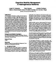
Figure 1. An interface constructed between three code generation domains. The interface constructed by the framework is made up of communication pairs, each pair encircled by a dotted ellipse. The first (sine) and last (xgraph) actors are to be run on the host workstation (CGC). The second block (analysis filter bank, made up of two polyphase FIR actors) is to be run on a DSP card (CG56). The third block (synthesis filter bank, made up of two polyphase FIR actors) is to be run using a VHDL simulator. The C in the top left corner signifies that a synthesized C program is managing the system at this level. In this case, a C program is generated which downloads the DSP code and starts the VHDL simulator. To build the various interfaces, we use send and receive actors as has previously been described for multiprocessor SDF code generation in [10]. These actors provide the synchronization between the prototyping and simulation engines. This is accomplished by having blocking reads and writes over the communication channels. By using multiprocessor SDF scheduling techniques, we are able to determine the static execution order of all primitive communication operations, and within each processor the execution order of all the communication actors within the subgraph. By embedding the communication operations into the execution order within each process, we are able to guarantee non-deadlock execution. Furthermore, by implementing send and receive actors that use blocking reads and writes over the common communication link, we are able to synthesize a self-timed implementation. The minimal communication link buffer size is easily derived from the maximal number of data tokens that accumulate on the corresponding dataflow arc in one SDF schedule iteration. To construct the interface between two tools, send and receive actors are spliced into the designer’s application specification. As stated earlier, for each new tool we require actors to communicate to and from the CGC domain. Thus the C language and SDF semantics provide a common communication channel for all of the simulation and hardware engines. A straightforward extension is to allow various tools to communicate directly if there exists a more optimal communication medium.
3.2
Interfacing code generated subsystems
Figure 1 shows an example system depicting the first type of interface supported. In this figure the interface is used to link three code generation domains. CGC provides the intermediate protocol to link the subsystems. Using the communication actors, a specialized interface is constructed between the various simulation and hardware engines (in this case, a DSP card, a VHDL simulator and a UNIX workstation). These communication actors are inserted automatically by using a multiprocessor SDF scheduler, with CGC acting as a shared communication channel between the target processors. A VHDL simulation, with a fundamental execution model
SDF-Simulation C++
SDF-Simulation C
C++
SDF
SDF
2:1
4:3
5:7
C
SDF
C
S-56X
C
S-56X
C
S-56X
4:7
Figure 2. Ptolemy simulation domain and CGC subsystem interface. In this example the CGC subsystem is constrained to running on the same host machine as Ptolemy. that is discrete-event, can be used to execute a portion of an SDF dataflow system. However, to guarantee that we do not introduce deadlock, we must ensure that the communication execution ordering determined by the multiprocessor SDF scheduler is followed in the synthesized VHDL implementation. In our framework, this is accomplished by restricting the VHDL program to a single sequential thread of control. Individual SDF actor firings in the sequential schedule are implemented with sequential blocks of sequential statements in VHDL. No branching into or out of such code blocks is allowed. The ability to completely determine the schedule and data production/consumption activity at compile time allows the firing order and all data references and assignments to be determined before the VHDL code is generated. The sequence of VHDL statements matches the sequence of the SDF schedule. The variable references and assignments made in the VHDL code are performed so as to preserve the identity of all tokens transferred in a single SDF schedule iteration. Each token may have a unique variable identifier, or variable names may be shared assuming that no token variable is overwritten until all references to that variable have been completed. The ANSI/IEEE Std 1076-1993 version of the VHDL language [11] provides for the use of foreign subprograms or architectures within a VHDL description. Such foreign subprogram calls or component architectures may be used, where supported in C, to realize the send and receive actors in the dataflow graph which handle interprocess communication through CGC. The required use of separate entities for communication makes it more challenging to implement the VHDL subsystem with a single thread of control. In one vendor's implementation of VHDL simulation, the VSS Expert package from Synopsys, the use of foreign component architectures is supported. The C-Language Interface (CLI) of VSS Expert [12] supports VHDL components which are entirely implemented in C. Within such CLI components, calls to communication routines realize the send and receive actions between the VHDL-simulated subsystem and the remaining codegenerated subsystem. The subsystem implemented in VHDL is created by threading code blocks associated with each dataflow actor firing together in a single VHDL process, as described above. This is similar to how dataflow is implemented with code generation in C or other languages with sequential statement semantics. A single thread of control is enforced by sending wakeup signals to CLI components which perform communication operations, and using wait statements to suspend execution while waiting for CLI component operations to complete. By combining the sequential statement semantics of VHDL processes with VHDL components which perform the synchronization and communication in the correct sequence, the dataflow semantics of the VHDL simulation subsystem are preserved and the correct functional behavior is implemented in the VHDL simulation.
C
SDF
VHDL
C
VHDL
C
VHDL
Figure 3. General Ptolemy simulation interface. The analysis and synthesis filter bank blocks are identical to those described in figure 1.
3.3
Incremental compilation simulation domains
into
the
Ptolemy
The second type of interface that can be automatically constructed by the framework allows for the incremental compilation of a code generation subsystem into a monolithic SDFsimulation actor. Thus the code generation subsystem boundary must obey SDF semantics. Special communication actors are spliced at the subsystem boundary. This type of interface is shown in figure 2. The spliced-in stars allow for the generation of C++ code which will be used to construct the monolithic SDF-simulation actor. In particular, these actors generate the code for the input and output ports of the SDF-simulation actor, which is being constructed. These communication actors are provided in the framework and can reused for all simulation and hardware engines which have the primitive CGC communication actors required by this framework. Figure 3 depicts how we can combine both types of interfaces allowing for a generalized incremental compilation facility which can make use of any number of simulation and hardware engines. In this example, a monolithic SDF-simulation actor is generated which makes use of both a DSP card and a VHDL simulator.
4. EXAMPLES 4.1
Incremental Compilation into Ptolemy
Figure 4 shows an example in which a CGC subsystem has been substituted in place of a compute-intensive SDF simulation subsystem, thus yielding a 300% speedup. This example CD - 44.1 kHz Polyphase filter bank
2:1
4:3
5:7
4:7 0
���� ���� ���� ����
160 �� ���� �� �� ���� ������ �� ���� ������ ���� �� �� �� ������ 147
50
100
150
DAT - 48 kHz
Top level application specification 0
50
100
150
Figure 4. CD (44.1 kHz) to DAT (48 kHz) sample rate conversion. The polyphase filter bank is incrementally compiled from CGC into a monolithic simulation SDF actor. The input (CD) and output (DAT) signals plots are shown.
016), the State of California MICRO program, and the following companies: Bell Northern Research, Cadence, Dolby, Hitachi, Lucky-Goldstar, Mentor Graphics, Mitsubishi, Motorola, NEC, Philips, and Rockwell. José Luis Pino is also supported by AT&T Bell Laboratories as part of the Cooperative Research Fellowship Program.
Top level application specification
C
Analysis S-56X
Synthesis VHDL
REFERENCES [1]
Figure 5. An eight channel perfect reconstruction filter bank. The subsystem is run on a DSP card installed in the workstation and the Synopsys VSS Expert VHDL simulator. The top-level description is run using the SDF simulation domain. implements CD to DAT sample rate conversion efficiently, through a cascade of polyphase FIR filters. Here the CGC subsystem is compiled into a monolithic SDF actor which can be added to the designer’s block library for future use. Note that this sample-rate conversion (44.1kHz to 48kHz) is non-trivial and exemplifies the power inherent to the SDF model of computation. To code this sample rate conversion by hand without using the SDF model of computation would be a difficult task.
4.2
Hardware/simulation engines in simulation loop
Figure 5 shows a filter bank subsystem that runs on a S-56X DSP board (using a Motorola 56001 DSP) and the Synopsys VSS Expert VHDL simulator while the top-level application specification executes using the SDF-simulation domain in Ptolemy. A monolithic SDF-simulation block is synthesized for the code generation subsystem. The SDF block manages the DSP board, properly downloading and initializing the subsystem application code and the VHDL simulator.
5. CONCLUSIONS In this paper, we have introduced a framework which can interface tools in a high-level DSP synthesis environment. To add a new tool to the framework, the DSP system designer must only define two pairs of primitive communication actors. From this, we can construct interfaces between external tools or between these tools and the high-level DSP synthesis environment. The interfacing techniques described in this paper can be adapted for other high-level DSP synthesis environments currently available. We plan on extending this work to include other models of computation in addition to synchronous dataflow.
ACKNOWLEDGMENTS This research is part of the Ptolemy project, which is supported by the Advanced Research Projects Agency and the U.S. Air Force (under the RASSP program F33615-93-C-1317), the Semiconductor Research Corporation (SRC) (project 95-DC-324-
E. A. Lee and D. G. Messerschmitt, “Synchronous data flow,” Proceedings of the IEEE, vol. 75, no. 9, pp. 1235-1245, 1987. [2] J. Buck, S. Ha, E. A. Lee, and D. G. Messerschmitt, “Ptolemy: A framework for simulating and prototyping heterogeneous systems,” International Journal of Computer Simulation, special issue on Simulation Software Development, vol. 4, pp. 155-182, 1994. http://ptolemy.eecs.berkeley.edu/papers/JEurSim [3] D. Becker, R. K. Singh, and S. G. Tell, “An engineering environment for hardware/software co-simulation.,” Proceedings of the 29th ACM/IEEE Design Automation Conference, Anaheim, CA, USA, pp. 129-134, 1992. [4] R. K. Gupta, C. N. Coelho, Jr., and G. De Micheli, “Synthesis and simulation of digital systems containing interacting hardware and software components,” Proceedings of the 29th ACM/IEEE Design Automation Conference, Anaheim, CA, USA, pp. 225-30, 1992. [5] M. Pankert, S. Ritz, and H. Meyr, “Integration of digital signal processing hardware into a system level simulation environment,” Proceedings of the European Simulation Multiconference, York, U.K., pp. 147-151, 1992. [6] J. L. Pino, T. M. Parks, and E. A. Lee, “Automatic code generation for heterogeneous multiprocessors,” Proceedings of the IEEE International Conference on Acoustics, Speech, and Signal Processing, Adelaide, South Australia, vol. 2, pp. 445-448, 1994. http://ptolemy.eecs.berkeley.edu/papers/autoMultiCodeGen [7] J. Reekie and M. Meyer, “The host-engine software architecture for parallel digital signal processing,” Proceedings of the Australian Workshop on Parallel and RealTime Systems, Melbourne, Australia, 1994. [8] J. L. Pino, S. S. Bhattacharyya, and E. A. Lee, “A Hierarchical Multiprocessor Scheduling Framework for Synchronous Dataflow Graphs,” UC Berkeley UCB/ERL M95/36, 1995. http://ptolemy.eecs.berkeley.edu/papers/erl-95-36 [9] J. Buck, S. Ha, E. A. Lee, and D. G. Messerschmitt, “Multirate signal processing in Ptolemy,” Proceedings of the IEEE International Conference on Acoustics, Speech, and Signal Processing, Toronto, Ont., Canada, vol. 2, pp. 12451248, 1991. [10] J. L. Pino, S. Ha, E. A. Lee, and J. T. Buck, “Software synthesis for DSP using Ptolemy,” Journal of VLSI Signal Processing, vol. 9, no. 1-2, pp. 7-21, 1995. http://ptolemy.eecs.berkeley.edu/papers/jvsp_codegen [11] “IEEE Standard VHDL Language Reference Manual,” IEEE ANSI/IEEE Std 1076-1993, 1994. [12] “VSS Expert Interfaces V3.2b,” Synopsys, Inc., 700 East Middlefield Rd., Mountain View, CA 94043 Document Order Number 1US01-10062, 1995.