Nov 2, 2016 - interference inside a wireless body area network (WBAN). Our proposal ... windows (CW) and probably use switched orthogonal channel. Simulation ... monitor physical activities and capture vital signs as glucose percentage ...
Interference Avoidance Algorithm (IAA) for Multi-hop Wireless Body Area Network Communication Mohamad Jaafar Ali∗ , Hassine Moungla∗ , Ahmed Mehaoua∗
arXiv:1602.08658v1 [cs.NI] 28 Feb 2016
∗ LIPADE,
University of Paris Descartes, Sorbonne Paris Cité, 45 rue des saints pères, 75006, Paris, France Email: {mohamad.ali; hassine.moungla; ahmed.mehaoua}@parisdescartes.fr
Abstract—In this paper, we propose a distributed multi-hop interference avoidance algorithm, namely, IAA to avoid co-channel interference inside a wireless body area network (WBAN). Our proposal adopts carrier sense multiple access with collision avoidance (CSMA/CA) between sources and relays and a flexible time division multiple access (FTDMA) between relays and coordinator. The proposed scheme enables low interfering nodes to transmit their messages using base channel. Depending on suitable situations, high interfering nodes double their contention windows (CW) and probably use switched orthogonal channel. Simulation results show that proposed scheme has far better minimum SINR (12dB improvement) and longer energy lifetime than other schemes (power control and opportunistic relaying). Additionally, we validate our proposal in a theoretical analysis and also propose a probabilistic approach to prove the outage probability can be effectively reduced to the minimal.
I. I NTRODUCTION The pervasive use of wireless networks and the miniaturization have lead to the existence of WBANs. A person wears low power and cost sensor devices forms a star topology WBAN coordinated by single coordinator C. These sensors may be implanted inside or attached on human body. They can be used in various applications such as health monitoring, ubiquitous healthcare, sports and military. WBANs mainly monitor physical activities and capture vital signs as glucose percentage in blood, heart beats, respiration, body temperature and/or can record electrocardiography (ECG) [7], [8]. Recently, the IEEE 802.15.6 working group has defined new PHY and MAC layer proposals for WBANs. The standard requires the whole system to maintain proper function when up to 10 WBANs are co-located within a transmission range of 3 meters [15]. It has also adopted the two-hop communication scheme in the standard. Thus, adopting relay transmission is a very promising solution for co-channel interference reduction, energy efficiency and high reliable communications [12], [5], [13]. The unpredictable nature of WBANs and the high mobility make the coordination very hard. Due to the broadcast nature in WBANs, the nodes concurrently transmitting suffer from co-channel interference as acive periods can overlap. Co-channel interference problem motivates for the stringent requirements of interference avoidance schemes and protocols for reliable and energy efficient operation of WBANs. On the other hand, due to the constrained nature of WBANs (in terms
of energy, size and cost), advanced antenna techniques can not be used for interference avoidance as well as power control mechanisms used in cellular networks are not applicable to WBANs [12], [13], [8]. However, in this work, we focus our attention on problems related to co-channel interference and energy savings of a single WBAN. Thus, novel methods and schemes are required for intra-WBAN interference avoidance/mitigation. The rest of the paper is organized as follows. Section II shows the works related to interference mitigation/avoidance techniques in WBANs. Section III describes the system model and presents the proposed interference avoidance algorithm (IAA). Section IV explains the proposed FTDMA scheme. Section V shows the theoretical analysis of our proposal. Section VI presents and explains the experimental results. The conclusions and future works are drawn in section VII. II. R ELATED W ORKS Recent studies show multi-hop schemes have a lower power consumption in comparison to one-hop scheme. However, using relays reduces the WBAN interference and consequently the power consumption. Authors of [5] propose a singlerelay cooperative scheme where the best relay is selected in a distributed fashion. Also, authors of [10] propose a prediction-based dynamic relay transmission scheme through which the problem of "when to relay" and "who to relay" are decided in an optimal way. The interference problem among multiple co-located WBANs is investigated in [5]. The authors show cooperative two relay communication with opportunistic relaying significantly mitigates WBAN interference. Authors of [13] investigate the problem of coexistence of multiple non coordinated WBANs. This study provides better co-channel interference mitigation. However, more recent works conducted in [6] propose a scheme for joint twohop relay-assisted cooperative communication integrated with transmit power control. This scheme can reduce co-channel interference and extend the lifetime. On the other hand, other works prove that TDMA scheme is an attractive solution to avoid interference within an intraWBAN. Authors of [4] enables two or three coexisting WBANs to agree on a common TDMA schedule to reduce the interference. The work in [2] adopts a TDMA pollingbased scheme for traffic coordination inside a WBAN and
a carrier sensing (CS) mechanism to deal with inter-WBAN interference. Other research focuses on the performance at the coordinator that calculates SINR periodically. This calculation enables C to command its nodes to select appropriate interferece mitigation scheme [1]. Other studies of [4] analyze the performance of a reference WBAN. They evaluate the performance in terms of bit error rate, throughput and lifetime which have been improved by adoption of an optimized time hopping code assignment strategy. Works in [3] consider a WBAN where coordinator periodically queries sensors to transmit data. The network adopts the CSMA/CA and the nodes adopt link adaptation to select the modulation scheme according to the experienced channel quality. The research work of [14] solves the problem of interWBAN scheduling and interference by the adoption of a QoS based MAC preemptive priority scheduling approach. Whilst, researchers of [11] proposes a distributed interference detection and mitigation scheme through using adaptive channel hopping. Whereas, research works of [9] proposes a dynamic resource allocation scheme for interference avoidance among multiple coexisting WBANS through using orthogonal subchannels for high interfering nodes. Since TDMA is the most widely used protocol inside WBANs. Most of the recent works do not address problems related to interference minimization and energy maximization inside a WBAN. However, this protocol is not suitable for some applications with high transmission frequency and topology size of more then 12 body sensors. In this paper, we propose a distributed scheme (IAA) for interference avoidance inside a WBAN. The proposed scheme enables low interfering nodes to use base channel for transmitting to relays. Whilst, high interfering nodes extend their contention window and probably switch to another reserved channel.
• •
S = {si ∈ S, | (δsi ≥ δT hr ), ∀i} •
• •
Each source si ∈ S whose δ1si ≥ δT hr (i.e. there is no interference experienced) uses the base channel to communicate directly to the relays (case 1). Otherwise, source si ∈ IS (i.e. there is an interference experienced) extends the CW (doubles its backoff) to avoid the current interference. Afterwards, any source has already finished its CW extension retries sensing again the base channel. Algorithm 1 IAA - Sources Actions 1 2 3 4 5 7 8
21 22
We denote signal to interference and noise ratio (SINR) by 23 δ and SINR threshold by δT hr . Where δ is computed at a 24 25 node-of-interest by the following equation 1: 26
δ = PN
i=1 Ii
+ N0
(5)
B. Proposed Interference Avoidance Algorithm Description
20
PRX
(4)
G: set of all orthogonal channels reserved for all relays Ki ⊂ G ⇐⇒ Ki ∩ Kj = ∅, ∀i 6= j
We consider a fixed topology of a single WBAN con- 9 sisting of a fixed set of N nodes and C. We adopt two- 10 11 hop communication scheme and consider a beacon-enabled 12 slotted CSMA/CA between sources and relays and a flexible 13 TDMA between relays and C. However, each node (source 14 or relay) can operate on either of base or reserved channels. 15 Furthermore, two possible options [with- or without-] CW 16 extension can be used with base channel depending on the 17 18 interference level. 19 A. Model Definitions
(3)
TxR: set of all relays transmit successfully their messages to C in the current frame Ki : set of all orthogonal channels reserved for relay ri Ki = {Ki | Ki ∩ Kj = ∅, ∀i 6= j}
•
(2)
IS: set of all interfering sources where, each source has δ < δT hr , (IS ⊂ P), i.e, there is interference: IS = {si ∈ IS, | (δsi < δT hr ), ∀i}
6
III. S YSTEM M ODEL
P: set of all sources that have sensed data to transmit in the contention access period (CAP) of the current frame S: set of all sources, where, each source has δ ≥ δT hr , (S ⊂ P), i.e, there is no interference:
27
(1) 28 29 30
Where, PRX is the desired received power, Ii is the received 31 power from undesired transmitter i and N0 is the noise. In 32 33 addition, we also define the following sets:
input : P, δT hr , qT hr for i ← 1 to sizeof (P ) do if (δ1si ≥ δT hr ) then si ∈ S sendsM essageOn baseChannel in CAP-1A; end else ∴ si is an interfering source ⇔ si ∈ IS; si doublesCW & waits until CAP-1A finishes; if CWsi isOver then if δ2si ≥ δT hr then si ∈ IS sendsM essageOn baseChannel in CAP-1B; end else ∴ si is an interfering source again; si switchesT o reservedChannel & waits until CAP-1B finishes; if δ3si ≥ δT hr then si sendsM essageOn reservedChannel in CAP-2; end else q = 0; for m ← 1 to maxRetries do if δ3si < δT hr then q = q + 1; end if q > qT hr then si switchesT o baseChannel; break; end end end end end end end
If it succeeds (finds δ2si ≥ δT hr ), it transmits its message to relays using the base channel (case 2). Otherwise, source si ∈ IS experiences an interference again and switches to reserved channel (case 3) through which it starts again a new contention (meausres δ3). The following summarizes the different aforementioned cases. • Case 1: ∀ si ∈ S & δ1si ≥ δT hr , si uses base channel • Case 2: ∀ si ∈ IS & δ2si ≥ δT hr , si uses base channel with CW extension mechanism • Case 3: ∀ si ∈ IS & δ2si < δT hr , si uses reserved channel The Algo. 1 above shows the pseudocode of the IAA part runs at the sources.
BaseCh+CW
δ2si < δT hr , switchesCh
δ1si < δT hr , doublesCW
δ2si ≥ δT hr , si , transmits start BaseCh
δ3si < δT hr , switchesCh
ReservedCh
δ1si ≥ δT hr , si , transmits δ3si ≥ δT hr , si , transmits
Figure 1: Actions taken by a source at any CAP period
C. Proposed Superframe Structure To support our proposed scheme, a new superframe structure is composed of two main parts, a CAP part and TDMA part as shown in Fig. 2. The CAP part is composed of CAP-1 and CAP-2 sub-parts. Whereas, the TDMA part is composed of fixed and flexible TDMA sub-parts. CAP-1 is also composed of CAP-1A (covers cases 1) and CAP-1B (covers cases 2) sub-parts. For thoroughly explanation, all the sources’ transmissions done on base channel (cases 1 and 2) must complete just before the end of CAP-1. Whereas, all sources’ transmissions done on reserved channel (case 3) must start just after the end of CAP-1 and complete just before the end of the second period CAP-2. On the other hand, after all the sources’ transmissions to the relays complete in both CAP-1 and CAP-2. The TDMA part starts through which some set of relays commence transmitting their pending messages to C using their corresponding slots of the TDMA schedule. Regarding the fixed part of the frame, a pre-defined fixed number of time slots is assigned to a specific set of relays. Based on the network interference level in the current frame, C estimates a flexible number of time slots for the next frame that will be used by an unexpected set of relays. D. Source to Relay Communication The communication between sources and relays is achieved through three successive periods. During the period CAP-1A, each source si and whose δ1si ≥ δT hr uses the base channel to transmit its message to the relays (case 1). Otherwise, si is considered interfering, if it is so, it extends its CW to avoid the interference. It waits until CAP-1A finishes. Afterwards, it retries and if finds its δ2si ≥ δT hr , it uses the base channel again through which it transmits its message to the relays during the the CAP-1B (case 2). Otherwise, if it finds its δ2si < δT hr , it switches to the reserved channel through which it starts a new contention commencing just after the end of CAP1B (case 3). However, Fig. 1 shows all the different possible actions taken by a source at any CAP period. E. Relay Actions and Channel Synchronization To let the sources have already switched to reserved channel transmitting their messages correctly. Our proposal ensures
that there are some set of relays ready to receive these transmissions. Initially, all the relays (R) listen on base channel. Each relay ri ∈ R measures periodically δri in a pre-defined segment of each CAP, if it finds δri ≥ δT hr , then ri can receive on base channel. Otherwise, if it finds δri < δT hr , i.e, ri experiences an interference, it then switches to the reserved channel where it starts listening again. Whenever a relay encounters a collision, it immediately transmits a jam signal to inform the transmitting sources to stop transmitting and waits a while (simple backoff) and then retries [16]. According to the relays’ actions aforementioned, the same process takes place at both base and reserved channels. Afterwards, when all receptions at relays are complete, each relay waits TDMA to commence transmitting to C. The following Algo. 3 shows the pseudocode of the IAA part runs at the relays. 1
Figure 2: Proposed Superframe Structure
F. Relays to Coordinator Communication After all the transmissions are complete, all the sources and relays switch back to base channel. However, according to the aforementioned proposed FTDMA scheme, C forms the fixed part of the next frame consisting of TS time slots, where, TS = B + Re + BW, B is the number of slots assigned for nodes relaying data on the behalf of the sources that use the base channel (case 1). Re is the number of slots assigned for nodes relaying data on the behalf of the sources that use the reserved channel (case 3) and BW is the number of slots assigned for nodes relaying data on the behalf of the sources that use the base channel with CW extension (case 2). Then, depending on the interference level experienced in the previous superframe, C specifies and adds the number of free slots of the flexible part to the fixed part to form the whole superframe.
δ
CW with certain probability which equals δT jhr . Thus, at time instant i, we can calculate the average interference level at source s using the proposed probabilistic approach as follows: � � N −1 X δj δi = δj 1 − (8) δT hr j=1
The following Algo. 2 shows the pseudocode of the IAA part runs at the coordinator. Algorithm 2 IAA - Coordinator Actions 34 35 36 37 38 39 40 41 42 43 44
input : TxR, Interference-level ILk C Broadcasts Beacon bk m = 0; for i ← 1 to sizeof (T xR) do if C Acknowledges rsi then C includes IDrsi in fixed TDMA part of Beacon bk+1 m = m + 1; end end C forms fixed TDMA part of m slots C forms flexible TDMA part of n slots based on ILk C forms next Beacon bk+1 of (p = m + n) slots
Based on the probabilistic approach and the proposed scheme, δ any sensor with probability δT jhr doubles its contention window. If the source is in contention window case, it then probably (depending� on δ) � switches to the reserved channel
IV. P ROPOSED F LEXIBLE TDMA S CHEME (FTDMA) A node is considered active if C has received at least one message during the previous three frames. If C has received from m active nodes in the current frame, then, it allocates p (where p > m) slots in TDMA part of the next frame. The first m slots are allocated to the currently active nodes (fixed part) and the rest (n = p - m) slots are reserved to the newly incoming nodes (flexible part). See Fig. 2. A node first listens to the beacon, if it finds its ID in the fixed TDMA part, it transmits its message in one of the m slots. However, if it does not find its ID, it then randomly selects one of the n empty slots (flexible TDMA part) and transmits its meassage in that slot. If the message is successfully sent to C, C will allocate a slot for the node in the next frame. Otherwise, C will not include its ID in the next frame. In such cases, a node keeps trying different empty slots randomly in every frame until a timeslot is assigned to it. Algo. 2 shows how C assigns slots to nodes in the next superframe.
j=1
� Where
δj δT hr
+
�
δj δT hr
�2 �
denotes the probability of the
source is being in case 2 or the probability of the source is being in case 3. The last line of PP r is based on the fact that the CDF is an increasing function of its argument. We define Ppr,I,i as the probabilistic approach deployment probability that a sensor node of WBAN doubles its contention window is Then: δi Pprob,I,i = P (δi > δT hr ) + P (δi < δT hr ) , (12) δT hr
V. T HEORETICAL A NALYSIS OF P ROPOSED IAA S CHEME Outage probability is a metric for the channel that states according to the variable δ at the received end, what is the probability that a capacity is not supported due to variable δ. In other words, outage probability denoted by (OP) at given δT hr is defined as the probability of δ value being larger than threshold δT hr . OP = P r (δ > δT hr )
2
δ
with probability of δT jhr . Lemma 1: We denote by PP r and Pout the outage probability of probabilistic approach and the outage probability of the original scheme respectively. Then, PP r < Pout , i.e. the probabilistic approach has better δ than that of the original scheme. Proof: Based on outage probability definition, we have: ! � �2 !! N −1 X δi δi + > δT hr PP r = p δi 1 − δT hr δT hr i=1 (9) ! N −1 N −1 N −1 X X X δi3 δi2 + (10) =p δi > δT hr + δ δ2 i=1 T hr i=1 i=1 T hr N −1 X < p δj > δT hr = Pout (11)
which is greater than Pi = P (δavg > δT hr ). Algorithm 3 IAA - Relays Actions
(6)
input : TxR, δT hr
We denote by Pout the probability that the total interference 45 for k ← 1 to sizeof(T xR) do rk listensOn baseChannel; at time instant i is being larger than δT hr at a given source s 46 47 if δ1rk ≥ δT hr then of the WBAN. We denote by δj the received δ from sensor j 48 rk receivesOn baseChannel; end at sensor s in WBAN. Then, we calculate this probability by 49 50 else the following formula: 51 rk switches&ListensOn reservedChannel; 52 if δ2rk ≥ δT hr then N −1 X 53 rk receivesOn reservedChannel; Pout = δj > δT hr (7) 54 end j=1
55
else
56
We present a probabilistic approach which we prove analyt- 57 end end ically it lowers the outage probability. Any sensor s whose 58 59 end received δ is lower than a given threshold, it doubles its contention window iff δj < δT hr . So, sensor s extends its
rk switchesTo baseChannel after maxRetries;
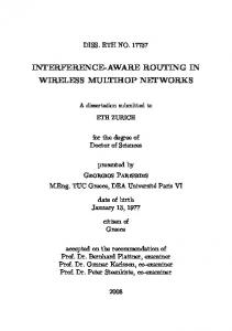
VI. E XPERIMENTAL R ESULTS
WBAN Minimum SINR versus Time 40 35 Minimum SINR [dB]
Simulation time 50 minutes Noise floor -100 dBm Data rate 250 kbps Packet size 12 bytes Frequency 2.4 GHz Path loss exponent(α) 4.22 Table I: Simulation Parameters
A. Simulation Environment and Setup
B. WBAN Minimum SINR We have chosen the most common metric SINR to evaluate the interference level and show how better our proposed IAA scheme mitigates the interference than other schemes. The minimum SINR (δmin ) of the WBAN versus time for IAA scheme is compared to the cooperative communication integrated with transmit power control (PC) [6] and CSMA/CA with opportunistic relaying (OR) [5], [16] schemes. As can be clearly seen in Fig. 3, IAA scheme achieves a higher δmin (12dB improvement) than PC and OR schemes. PC provides a higher δmin (7dB improvement) than OR scheme since the former adopts the power control mechanism where the nodes (sources and relays) dynamically adjust their power level. Accordingly, controlling power reduces the interference at other nodes of WBAN and hence improving their δmin . When some nodes experience high interference, they have to wait the channel to become free and then retry. However, instead of waiting, in the proposed IAA scheme, these high interfering nodes extend the CW and probably switch to reserved channel for avoiding interference and so their corresponding δmin s are increased. Furthermore, only IAA use flexible TDMA to communicate to C for avoiding the interference. As a result, our proposed IAA scheme avoids the WBAN interference through increasing the minimum SINR. C. Outage Probability We have evaluated the average SINR δ of the WBAN versus the SINR threshold δT hr in Fig. 4, where a higher δ which corresponds to a lower outage probability is obtained when the interference threshold is increased. This figure compares the average δ for the proposed IAA scheme and that for the OR scheme. As can be clearly seen in this figure, the proposed IAA scheme achieves a higher average δ for all SINR interference thresholds greater than -45 dB which is quite efficient in the case of WBANs. Thus, increasing SINR interference thresholds puts more sensors in the interference
25 20 15 10 Proposed IAA Scheme Power Control Scheme OR Scheme
5 0 0
10
20 30 Time [minutes]
40
50
Figure 3: WBAN Minimum SINR versus Time of proposed IAA scheme compared to that of power control (PC) and opportunistic relaying (OR) schemes
set. These sensors will use CW extension mechanism and probably the reserved channel to avoid the interference and hence improving their SINRs. In addition, it is evident to see, when the interference threshold reaches -45 dB, the proposed IAA scheme approaches the OR scheme in terms of average δ. However, it is important to note that the interference threshold can be adaptively selected according to the interference level.
Average SINR versus SINR Threshold 40
IAA Scheme OR Scheme
38 36
Average SINR δ (dB)
We have considered a static WBAN consisting of N = 12 source nodes and a set of relay nodes R = 4 located in an area of 2×2 m2 . All the nodes operate in a half-duplex mode and use the same transmission power at 0 dBm. In this simulation, we focus our attention on the performance of three important metrics; minimum SINR, outage probability and WBAN energy residue. For brevity, the rest of simulation parameters are listed in table I above.
30
34 32 30 28 26 24 22 20 −45
−40
−35
−30
−25
−20
−15
−10
SINR Threshold δThr (dB)
−5
0
Figure 4: Average SINR versus SINR Interference Threshold of the proposed IAA scheme compared to that of opportunistic relaying (OR) scheme
D. WBAN Energy Residue In order to evaluate our proposed IAA scheme how better extends the energy lifetime of the WBAN than other schemes. We have chosen energy residue which is linearly related to the most stringent factor (energy) in WBANs. We define WBAN energy residue (ER) at time t as the sum of remaining energies in the battery of each sensor of the WBAN. ER versus time
for three different schemes is compared and shown in Fig. 5. As can be clearly seen in this figure, ER of IAA scheme outperforms and is always higher than ER of OR and PC schemes. ER of IAA decreases slightly whilst in the other schemes decreases sharply. This ensures a longer WBAN energy lifetime. However, with the proposed IAA scheme, the packet collisions and retransmissions are also minimized because all the interfering nodes dynamically use the CW extension mechanism and probably the channel switching technique. In PC scheme, a power control mechanism adjusts dynamically the power level at sources and relays and hence reducing the energy consumption in the whole WBAN. On the other hand, the absence of power control from OR scheme increases the energy consumption at the sources and relays and thus shortening the energy lifetime of the whole WBAN. As a result, our proposed IAA scheme outperforms other schemes and better extends the WBAN’s energy lifetime. Furthermore, adopting a flexible TDMA (PC and OR do not adopt) in our proposed scheme to avoid interference decreases also the whole WBAN energy consumption. WBAN Energy Residue versus Time WBAN Energy Residue [milliJoule]
100 90 80 70 60 50 40 0
Proposed IAA Scheme Power Control Scheme OR Scheme 10
20 Time [minutes]
30
40
Figure 5: WBAN Energy Residue versus Time of the proposed IAA scheme compared to that of power control (PC) and opportunistic relaying (OR) schemes VII. C ONCLUSION In this paper, we propose a distributed cooperative multihop scheme (IAA) adopts contention window extension mechanism integrated with channel switching technique to avoid co-channel interference of a single WBAN. We also propose a flexible TDMA between relays and coordinator. Our proposal aims to avoid co-channel interference and extends the WBAN energy lifetime. Furthermore, our proposed IAA scheme has been evaluated by simulation and compared with other schemes showing 12dB improvement in the minimum SINR and significantly extends the WBAN energy lifetime. Additionally, theoretical analysis validated our approach. Thus, we propose a probabilistic approach and prove the outage probability is reduced to the minimal. As a future work, it is worth to adapt our proposal for the dynamic topology taking
into account the body movement in an environment of multiple coexisitng WBANs. R EFERENCES [1] Yang, Wen-Bin and Sayrafian-Pour, Kamran, Interference Mitigation Using Adaptive Schemes in Body Area Networks, International Journal of Wireless Information Networks, pages 193-200, 2012 [2] Chen, G. Chen, W. and Shen, S., 2L-MAC: A MAC Protocol with TwoLayer Interference Mitigation in Wireless Body Area Networks for Medical Applications, IEEE International Conference on Communications (ICC), pages 3523-3528, 2014 [3] Martelli, F. and Verdone, R. and Buratti, C., Link Adaptation in IEEE 802.15.4-based Wireless Body Area Networks, Personal, Indoor and Mobile Radio Communications Workshops (PIMRC Workshops), 2010 IEEE 21st International Symposium, pages 117-121,2010 [4] Mahapatro, J. and Misra, S. and Manjunatha, M. and Islam, N., Interference mitigation between WBAN equipped patients, Ninth International Conference on Wireless and Optical Communications Networks (WOCN),pages 1-5,2012 [5] Dong, Jie and Smith, David, Opportunistic relaying in wireless body area networks: Coexistence performance, IEEE International Conference on Communications (ICC), pages 5613-5618, 2013 [6] Dong, Jie and Smith, David,Joint relay selection and transmit power control for wireless body area networks coexistence, IEEE International Conference on Communications (ICC), pages 5676-5681, 2014 [7] Javaid, Nadeem and Khan, NA and Shakir, M and Khan, MA and Bouk, Safdar Hussain and Khan, ZA, Ubiquitous healthcare in wireless body area networks-a survey, arXiv preprint arXiv:1303.2062, 2013 [8] Movassaghi, Samaneh and Abolhasan, Mehran and Lipman, Justin and Smith, David and Jamalipour, Abbas, Wireless Body Area Networks: A Survey, IEEE Communications Surveys Tutorials, pages 1658-1686, 2014 [9] Movassaghi, Samaneh and Abolhasan, Mehran and Smith, David, Smart spectrum allocation for interference mitigation in Wireless Body Area Networks, IEEE International Conference on Communications (ICC), pages 5688-5693, 2014 [10] Feng, Hui and Liu, Bin and Yan, Zhisheng and Zhang, Chi and Chen, Chang Wen, Prediction-based dynamic relay transmission scheme for Wireless Body Area Networks, IEEE 24th International Symposium Personal Indoor and Mobile Radio Communications (PIMRC), pages 2539-2544,2013 [11] Shipeng Liang and Yu Ge and Shengming Jiang and Hwee Pink Tan, A lightweight and robust interference mitigation scheme for wireless body sensor networks in realistic environments, IEEE Wireless Communications and Networking Conference (WCNC), pages 1697-1702, 2014 [12] Movassaghi, Samaneh and Abolhasan, Mehran and Smith, David, Interference Mitigation in WBANs: Challenges and Existing solutions, Workshop on Advances in Real-time Information Networks,2013 [13] Jie Dong and Smith, D., Cooperative body-area-communications: Enhancing coexistence without coordination between networks, IEEE 23rd International Symposium on Personal Indoor and Mobile Radio Communications (PIMRC), pages 2269-2274, 2012 [14] Jamthe, Anagha and Mishra, Amitabh and Agrawal, Dharma P, Scheduling schemes for interference suppression in healthcare sensor networks, IEEE International Conference on Communications (ICC), pages 391396, 2014 [15] IEEE Standard for Local and metropolitan area networks - Part 15.6: Wireless Body Area Networks,pages 1-271,2012 [16] Dong, Jie and Smith, David, Coexistence and Interference Mitigation for Wireless Body Area Networks: Improvements using On-Body Opportunistic Relaying, arXiv preprint arXiv:1305.6992, 2013