In UWB receiver, a Chirp-UWB is prepared as a template waveform. The received signal before. UWB communication is correlated with the Chirp-UWB template.
PROCEEDINGS OF THE 2008 IEEE INTERNATIONAL CONFERENCE ON ULTRA-WIDEBAND (ICUWB2008), VOL. 1
Interfering Signal Detection by using Chirp-UWB Template Waveform Kohei Ohno1) 2) and Tetsushi Ikegami2) 1)
Department of Applied Electronics, Tokyo University of Science 2639 Yamazaki, Noda, Chiba, 278-8510, Japan
2)
Department of Electronics and Bioinformatics, Meiji University 1-1-1 Higashimita, Tama-ku, Kawasaki, 214-8571, Japan
Abstract— This paper discusses an interference detection technique for Ultra Wideband (UWB) to share the spectrum with other radio system. A Detection And Avoidance (DAA) technique are required in UWB system from some countries regulations. In most of interference mitigation techniques, it is required to detect existence of interfering signal and its band. However, some band pass filters are needed to detect various interfering bands detected used by the conventional energy detection. In this paper, the correlation detection is applied for the interfering signal detection without band pass filters. In UWB receiver, a Chirp-UWB is prepared as a template waveform. The received signal before UWB communication is correlated with the Chirp-UWB template waveform, and the signal is integrated. The integral period is decided from sweep function of the Chirp-UWB depending on the interfering bands. The sweep function of the Chirp-UWB is also considered to improve the performance. The sine function is adopted for the sweep function. The miss Detection Error Rate (DER) and False Alarm Rate (FAR) are evaluated to show the effectiveness of proposed interference detection technique. Index Terms—Ultra Wideband (UWB), Chirp, Detection And Avoidance (DAA), Interfering Signal Detection, Correlation.
(Band Pass Filter) are needed to detect the interfering bands. A chirp technology is attracted attention, since it is proposed for low data rate PAN (Personal Area Network) system in IEEE802.15.4a working group [6] [7]. The chirp is utilized for not only communications or radars, but also channel estimation techniques [8] The effect of interference from various kinds of systems on UWB is investigated and a multi-carrier type template wave to mitigate the influence of IEEE802.11a interference is proposed [9]. The interference mitigation technique from UWB to OFDM system is also proposed. The pulse repetition interval of UWB system is set depending on the OFDM symbol duration not to be reduced UWB averaged power [10]. In this paper, an interfering signal detection technique using Chirp-UWB template wave is proposed. The technique is applied for correlation detection that is often used as the UWB demodulation method. The received interfering signal before UWB communications are correlated with Chirp template wave. The proposed technique is able to detect existence of interference and interfering bands without BPFs unlike the energy detection.
I. INTRODUCTION
II. SYSTEM MODEL
Spectrum sharing techniques are attractive because there is a real lack of frequency bands for radio systems. Ultra Wideband (UWB) is able to share the spectrum with other radio systems by spreading spectrum extremely widely [1]. However, in UWB system, there are potential interferences between UWB system and existing systems. The FCC (Federal Communication Commission) allocated a frequency band for UWB from 3.1GHz to 10.6GHz and determined transmission power to be a maximum of -41.3dBm/MHz in 2002 [2]. In both Japanese and European regulations, DAA (Detection And Avoidance) techniques are required to emit -41.3dBm/MHz in the 4GHz band [3][4]. Therefore, the interference mitigation techniques and the interference detection techniques are significant. Most of interference mitigation techniques are needed to detect presence of interfering systems or their emitting bands. The energy detection is a conventional radio signal detection technique [5]. It is possible to detect existence of interfering signals with simply hardware structure using integral circuits or ADCs (Analog to Digital Converter). However, the BPFs
978-1-4244-1827-5/08/$25.00 ©2008 IEEE
The chirp is a signal that a carrier frequency is swept. The various types of sweep functions are considered for the Chirp signal [11]. In general, the frequency is swept linearly. The typical linear up-chirp signal is expressed as following equation, v(t )
§P ·½ ° P sin ®2St ¨ t � f l ¸¾ ® 2 © ¹¿ ¯ ° 0 ¯ 'f P 'T
�T · § ¸ ¨ |t| d 2 ¹ © �else
, (1)
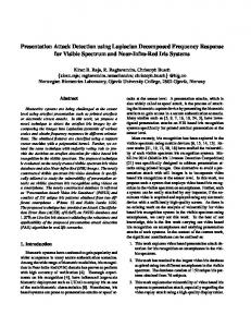
, (2) where P is frequency sweeping ratio, fl is sweeping start frequency, 'T is signal duration and 'f is bandwidth. An example of linear sweep function is shown in Figure 1 ('T=100ns, 'f=2GHz, fl=3.2GHz). The interfering signal is detected in the UWB receiver. In a pulse based UWB system, the correlation detection is often used. The received UWB pulse is correlated with a template waveform. In this paper, a Chirp-UWB is prepared as the template wave for the interference detections.
173
PROCEEDINGS OF THE 2008 IEEE INTERNATIONAL CONFERENCE ON ULTRA-WIDEBAND (ICUWB2008), VOL. 1 The proposed interfering signal detector structure is shown in Figure 2. The received signal before UWB communications is correlated with the Chirp-UWB template waveform. The signal is integrated. The integral period Tw and the center of integral period ti are decided from the sweep function as corresponding to the interfering band and its center frequency as in Figure 1. The correlation value ci is expressed as follow, 1 M
ci
M �1
¦³
ti �Tw 2 � mTi ti �Tw 2 � mTi
r (t ) v(t � mTi )dt
. (3) The correlation is repeated M times over and the mean correlation value is calculated to improve the detection sensitivity. The total interfering signal detection time Tcs equals M'T. The correlation value is compared with the threshold th. While the interfering signal is detected, the UWB communication is paused. Therefore, when the interfering system is existed, the correlation value is included the interfering signal i(t) and noise components n(t). m 0
䎩䏕䏈䏔䏘䏈䏑䏆䏜䎃䎾䎪䎫䏝䏀
'T
䎘䎑䎗 䎘䎑䎕 䎘䎑䎓 䎗䎑䎛 䎗䎑䎙 䎗䎑䎗 䎗䎑䎕 䎗䎑䎓 䎖䎑䎛 䎖䎑䎙 䎖䎑䎗 䎖䎑䎕 䎖䎑䎓
Pt + fl '䌦 fw Interfering Band
䌦l
䎓
ti
䎔䎓
Tw
䎕䎓
䎖䎓
䎗䎓
䎘䎓 䎙䎓 䎷䏌䏐䏈䎃䎾䏑䏖䏀
䎚䎓
䎛䎓
䎜䎓
䎔䎓䎓
Figure 1 An example Chirp-UWB sweep function. r(t)= i(t)+n(t) BPF
Interfering Band Integral
Sum of Correlation Values
ci > th ?
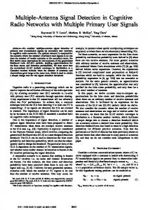
interfering signal and the Chirp-UWB template wave is should be larger. In Figure 3, the mean correlation value is illustrated with the integral period. The two kinds of signal duration Chirp-UWB is considered as 'T=100ns and 1000ns. The frequency is swept from 3.2GHz to 5.2GHz as Equation (1). The correlation values are calculated as the auto correlation values of both the Chirp-UWB and the interfering signal in period of 'T are normalized as one. From results, the correlation values indicate the maximum when Tw=12ns and 38ns with 'T=100ns and 1000ns chirp signal, respectively. The tendency of correlation values is almost same between the OFDM interfering signal and CW. Tw becomes longer, fw also becomes wider. Therefore, it is significant that Tw is chosen the smaller value, when various kinds of interfering signals are existed in coexisting bands with the UWB system. The interference detection performance is evaluated by a miss Detection Error Rate (DER) and a False Alarm Rate (FAR). The miss detection rate is calculated the error that an interfering signal cannot be detected when the interfering signal is actuary emitted, Whereas, the false alarm is the miss-judgment that the interfering signal is detected when the interfering signal is actuary not emitted. The DER performance is evaluated by I/N ratio (Interference to Noise signal power ratio). The interference power is defended as averaged power per sufficient long time. The noise power is defined with limited by the UWB bands assuming passed an ideal rectangular filter for UWB. The FAR performance is independent from I/N ratio because the errors are happened when the interfering signal is not emitted. The correlation values compared with the threshold are normalized by a mean correlation value between the noise and Chirp-UWB. Thus, the correlation value of the interfering signal equals to the correlation values of the noise, when the threshold is one.
i(t): interference n(t): noise Template Wave Chirp-UWB: v(t)
Table 1 interfering signal parameters (WiMAX) Parameter
Figure 2 Proposed interfering signal detector structure.
2048
Band Width: BW
22.8MHz
DF: Subcarrier frequency spacing
11.16kHz (=BW/N)
III. INTERFERING SYSTEM DETECTION BY CHIRP-UWB
TFFT : IFFT/FFT period
89.6us (1/DF)
TGI: Guard interval duration
11.2us (TFFT /8)
TSYM : Symbol interval
100.8us (TFFT + TGI)
Frequency Band (Carrier Frequency)
3.5GHz
Primary Modulation
16QAM ' 䎷䎠 䎔䎓 䎓 䏑䏖䎏䎃 ' 䏉 䎠 䎕䎪䎫䏝䎏䎃䎬䏑䏗䏈䏕䏉䏈 䏕䏈 䏑 䏆䏈 䎝䎺䏌䎰䎤䎻 ' 䎷䎠 䎔䎓 䎓 䎓䏑 䏖䎏䎃 ' 䏉 䎠䎕 䎪䎫䏝䎏䎃 䎬䏑 䏗䏈 䏕䏉䏈 䏕䏈 䏑䏆 䏈 䎝䎺䏌䎰䎤䎻 ' 䎷䎠 䎔䎓 䎓 䏑䏖䎏䎃 ' 䏉 䎠 䎕䎪䎫䏝䎏䎃䎬䏑䏗䏈䏕䏉䏈 䏕䏈 䏑 䏆䏈 䎝䎦䎺 ' 䎷䎠 䎔䎓 䎓 䎓䏑 䏖䎏䎃 ' 䏉 䎠䎕 䎪䎫䏝䎏䎃 䎬䏑 䏗䏈 䏕䏉䏈 䏕䏈 䏑䏆 䏈 䎝䎦䎺 ' 䎷䎠 䎔䎓 䎓 䏑䏖䎏䎃 ' 䏉 䎠 䎕䎪䎫䏝䎏䎃䎤䎺䎪䎱 ' 䎷䎠 䎔䎓 䎓 䎓䏑 䏖䎏䎃 ' 䏉 䎠䎕 䎪䎫䏝䎏䎃 䎤䎺䎪䎱
䎓 䎑䎓 䎚 䎓 䎑䎓 䎙 䎓 䎑䎓 䎘 䎦䏒䏕䏕䏈䏏䏄䏗䏌䏒䏑 䎃䎹 䏄䏏䏘 䏈
A. Linear Sweep Function The performances of the interfering system detection by using the Chirp-UWB template waveform are evaluated. As an example of interfering systems, the OFDM (Orthogonal Frequency Division Multiplexing) signal based on WiMAX (Worldwide Interoperability for Microwave Access) MAN (Metropolitan Area Network) system is considered. In this consideration, signal band width is fixed as 20MHz and the primary modulation is adopted 16QAM. The parameters are shown in Table 1. The frequency bands of the WiMAX system, differ among countries since the standardization is decided only under 6GHz by the standardization. In this paper, the center frequency is decided 3.5GHz that it a most common band for the WiMAX system. CW (Continuous Wave) interfering signal is also considered in the same frequency as WiMAX system [16]. The correlation period Tw is examined to improve the detection performance. The correlation value between the
Value
N: Number of FFT point
䎓 䎑䎓 䎗 䎓 䎑䎓 䎖 䎓 䎑䎓 䎕 䎓 䎑䎓 䎔 䎓
䎓
䎔䎓
䎕䎓
䎖䎓 䎗䎓 䎘䎓 䎙䎓 䎚䎓 䎬䏑 䏗䏈䏊䏕䏄䏏䎃 䎳䏈 䏕䏌䏒䏇䎋䎷䏚䎌 䎃䎾䏑 䏖䏀
䎛䎓
䎜䎓
䎔 䎓䎓
Figure 3 Mean of correlation value between interfering signal and Chirp UWB.
174
PROCEEDINGS OF THE 2008 IEEE INTERNATIONAL CONFERENCE ON ULTRA-WIDEBAND (ICUWB2008), VOL. 1
False Alarm The False Alarm Rate is shown in Figure 5. To consider the miss detection performance, the FAR should be less in lower threshold. Increasing correlation times, the FAR performance is improved. The FAR is also derived as well as DER performance. When correlation times M is stuffiest large number, the distribution of summing up correlation values between Chirp-UWB template wave and AWGN is assumed as the Gaussian distribution by the CLT. The variation and mean is expressed as follows, Variation Mean 2 2 2 V n1 V n 0 � P n1 2 Pcm P n1 V n 0 V cm 2 V nm 2 S . (10) M M , (9)
䎔䎓
䎓
䎔䎓
䎐䎔
䎔䎓
䎐䎕
䎔䎓
䎐䎖
䎔䎓
䎐䎗
䎧䎨 䎵
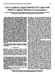
Miss-Detection The miss detection error rate performance is shown in Figure 4. The interfering signal is the WiMAX system. The proposed technique is possible to detect the interfering signal without the BPFs. To choose smaller threshold, the better DERs are obtained. The DER performances are improved increasing the correlation times M. However, the detection time Tcs is also extended. When the symbol duration of the Chirp-UWB is lengthened, the DER performance is also improved. The detection error performance is derived. The APD (Amplitude Probability Density) of OFDM signal is assumed as Gaussian distribution [12]. The correlation value of OFDM is also assumed to be Gaussian distribution, where Vs0 denotes the variation of it, the mean value becomes zero. The variation Vs1 and the mean Ps1 of absolute value of the correlation value between OFDM signal and the template value are expressed as follows, Variation Mean 2 2 2 2 P s1 V s 0 V s1 V s 0 � P s1 S , (4) . (5) The correlation value of AWGN is also derived similarly as Equation (4) and (5), where Vn0 is the variance of correlation values before taking absolute values, Vn1 and Pn1 are the variance and the mean taken absolute values of correlation values. When the correlation values are summing up M times and M is sufficient large number, the distribution is converged as Gaussian distribution by the central limittheorem (CLT). The variation Vcm and the mean value Pcm of correlation value with the receiving signal that is OFDM signal and the noise are derived as follows, Variation Mean � V s12 � V n12 2 P cm P s1 2 � P n12 V cm M , (6) . (7) The DER is derived as following equation as well as a BER performance in AWGN channel. § th � Pcm · 1 ¸ DER 1 � erfc¨¨ ¸ 2 , (8) © 2V cm ¹ Where erfc( ) is the complimentary error function. In Figure 4, DER performance derived from Equation (8) is shown when the correlation times M is 100. The DER is corresponding to the simulation results.
䎔䎓
䎰䎠䎔䎏䏗䏋䎠䎓䎑䎘 䎰䎠䎔䎏䏗䏋䎠䎔 䎰䎠䎔䎏䏗䏋䎠䎕 䎰䎠䎔䎏䏗䏋䎠䎘 䎰䎠䎔䎓䎓䎏䏗䏋䎠䎓䎑䎘 䎰䎠䎔䎓䎓䎏䏗䏋䎠䎔 䎰䎠䎔䎓䎓䎏䏗䏋䎠䎕 䎰䎠䎔䎓䎓䎏䏗䏋䎠䎘 䎰䎠䎔䎓䎓䎏䏗䏋䏈䏒䏕䏜
䎐䎘
䎐 䎗䎓
䎐 䎖䎓
䎐 䎕䎓
䎐 䎔䎓
䎓 䎬䎒 䎱䎃䎾䏇䎥䏀
䎔䎓
䎕䎓
䎖䎓
䎗䎓
䎖䎓
䎗䎓
(a) 'T=100
䎔䎓
䎐䎔
䎔䎓
䎐䎕
䎔䎓
䎐䎖
䎔䎓
䎐䎗
䎧䎨 䎵
䎔䎓
䎓
䎔䎓
䎰䎠䎔䎏䏗䏋䎠䎓䎑䎘 䎰䎠䎔䎏䏗䏋䎠䎔 䎰䎠䎔䎏䏗䏋䎠䎕 䎰䎠䎔䎏䏗䏋䎠䎘 䎰䎠䎔䎓䎓䎏䏗䏋䎠䎓䎑䎘 䎰䎠䎔䎓䎓䎏䏗䏋䎠䎔 䎰䎠䎔䎓䎓䎏䏗䏋䎠䎕 䎰䎠䎔䎓䎓䎏䏗䏋䎠䎘 䎰䎠䎔䎓䎓䎏䏗䏋䏈䏒䏕䏜
䎐䎘
䎐 䎗䎓
䎐 䎖䎓
䎐 䎕䎓
䎐 䎔䎓
䎓 䎬䎒 䎱䎃䎾䏇䎥䏀
䎔䎓
䎕䎓
(b) 'T=1000 Figure 4 The Detection Error Rate detected by Chirp-UWB 䎓
䎔䎓
䎐䎔
䎔䎓
䎐䎕
䎔䎓
䎐䎖
䎔䎓
䎐䎗
䎔䎓
䎐䎘
䎰䎠 䎔 䎰䎠 䎔 䎓 䎰䎠 䎔 䎓䎓 䎰䎠 䎔 䎓䎓 䎓 䎷䏋 䏈 䏒䏕䏜
䎩䎤 䎵
䎔䎓
䎔䎓
䎐䎔
䎓
䎔䎓 䎷䏋 䏕䏈 䏖䏋䏒䏏䏇
䎔䎓
䎔
Figure 5 False Alarm Rte detected by Chirp-UWB
The FAR is derived as follow. FAR
§ th � Pcm · 1 ¸ erfc¨¨ ¸ 2 © 2V cm ¹
(11) In Figure 5, the FAR is compared with simulation and Equation 11. The both FARs are not matched when the correlation times M is 10, because the distribution of the correlation value is not converged to the Gaussian distribution. When M is increased to 100, the FAR calculated from Equation 11 is corresponding to the simulation result. B. Sine Sweep Function To improve the interference detection performance, the sweep function is modified to the sine function as follow,
175
PROCEEDINGS OF THE 2008 IEEE INTERNATIONAL CONFERENCE ON ULTRA-WIDEBAND (ICUWB2008), VOL. 1 [8]
�T · § ¨ |t| d ¸ 2 ¹ © �else , (12)
where, p is a frequency constant, q is an amplitude constant, and I is a phase constant of the sweep function [11]. In this consideration, p is fixed to 2. To improve the detection performances, the spectrum of Chirp-UWB is formed as the power spectrum density to become larger in interfering bands. In Figure 6, the sweep functions are illustrated that q is set 20, 40, and 60. I is adjusted as the larger spectrum density is obtained in the interfering band. An example of the Chirp-UWB spectrum is shown in Figure 7. The spectrum density of the sine sweep function Chirp becomes lager than the Chirp signal with linear sweep function in 3.5GHz bands. The DER performance detected by the sine sweep function chirp template waveform is shown in Figure 8, when the threshold is set as two. Tw is also decided to be obtained larger correlation values. The detection error rate performance is improved about 2dB than the linear sweep function. The performance becomes better when the amplitude constant of sine function q is chosen larger value, because the power spectrum density of the chirp signal is varied widely. Therefore, non-linear sweeping function is effective to improve the performance when the interfering bands are predictable.
[9]
[10]
[11]
[12]
[13]
Hao Shen, and Antonia Papandreou-Suppappola, “Diversity and Channel Estimation Using Time-Varying Signals and Time-Frequency Techniques”, IEEE Transactions on Signal Processing, Vol. 54, No. 9, pp.3400-3413, Sep. 2006. Kohei Ohno, Tetsushi Ikegami, “Interference Mitigation Study for UWB Radio Using Template Waveform Processing”, IEEE Transactions on MTT, Vol. 54 No. 4, pp.1782-1792, Apr. 2006.㩷 Kohei Ohno, Tetsushi Ikegami, “Interference Mitigation Technique for Coexistence of Pulse based UWB and OFDM”, Hindawi Publishing, Eurasip Journal on Wireless Communications, Feb. 2008 Shyumpei Ida, Keisuke Doi, Ryuji Kohno, “A Study on Non-Linear Swept Chirp Waveform for UWB Multi Access Communication”, IEICE Tech. Report, WBS2003-225, Vol.103, No.715, pp. 197-202, Mar. 2004 Daido Yoshimasa, “Probability distribution for voltage instantaneous values of multi-carrier communication systems”, IEICE Tech. Report, RCS2005-53, Vol.105, No.196, pp. 79-83, Mar. 2005 IEEE, "Part 16: Air Interface for Fixed Broadband Wireless Access Systems", IEEE Std 802.16e-2005 and IEEE Std 802.16-2004/Cor1-2005, Dec. 2005
䎩䏕䏈 䏔䏘䏈 䏑 䏆䏜䎃䎾䎪䎫 䏝䏀
v (t )
ª 'f ½º p § · P ° P sin «2St ® sin ¨ 2S t � I ¸ � t � f l ¾» ® 2 ' 2 q T © ¹ ¿¼ ¬ ¯ ° 0 ¯
䎘 䎑䎗 䎘 䎑䎕 䎘 䎑䎓 䎗 䎑䎛 䎗 䎑䎙 䎗 䎑䎗 䎗 䎑䎕 䎗 䎑䎓 䎖 䎑䎛 䎖 䎑䎙 䎖 䎑䎗 䎖 䎑䎕 䎖 䎑䎓
䎯䏌䏑 䏈䏄䏕 䏔䎠 䎕 䎓 䏔䎠 䎗 䎓 䏔䎠 䎙 䎓 䎓
IV. CONCLUSION
[4]
[5] [6]
[7]
䎗䎓
䎘䎓 䎙䎓 䎷䏌䏐䏈䎃䎾䏑 䏖䏀
䎚䎓
䎛䎓
䎜䎓
䎔䎓 䎓
䎘
䎓
䎓
䎐䎘
䎐䎘 䎳䏒䏚䏈䏕䎃䎾䏇䎥䏀
䎳䏒䏚䏈䏕䎃䎾䏇䎥䏀
䎘
䎐䎔䎓 䎐䎔䎘
䎐䎔䎓 䎐䎔䎘
䎐䎕䎓
䎐䎕䎓
䎐䎕䎘
䎐䎕䎘
䎐䎖䎓 䎕䎑䎘
䎖
䎖䎑䎘 䎗 䎗䎑䎘 䎘 䎘䎑䎘 䎩䏕䏈䏔䏘䏈䏑䏆䏜䎃䎾䎪䎫䏝䏀
䎙
䎙䎑䎘
䎐䎖䎓 䎕䎑䎘
䎖
䎖䎑䎘 䎗 䎗䎑䎘 䎘 䎘䎑䎘 䎩䏕䏈䏔䏘䏈䏑䏆䏜䎃䎾䎪䎫䏝䏀
Moe Z. Win, Robert A. Scholtz, “Ultra-Wide Bandwidth Time Hopping Spread-Spectrum Impulse Radio for Wireless Multiple-Access Communication”, IEEE Trans. Communications, Vol. COM-48, No.4, pp. 679-689, Apr. 2000. FCC, ET Docket 98-153, “First Report and Order: Revision of Part 15 of the Commission’s Rules Regarding Ultra-Wideband Transmission Systems”, Adopted: February 14, 2002, Released: April 22, 2002. Ministry of internal Affairs and Communications, “The report of UWB radio system group”, February 2005. Electronic Communications Committee, “ECC Decision of 24 March 2006 amended 6 July at Constanta on the harmonized conditions for devices using Ultra-Wideband(UWB) technology in bands below 10.6GHz”, CEPT (European Conference of Postal and Telecommunications Administrations), Jul. 2007. Harry Urkowitz, “Energy Detection of Unknown Deterministic Signals”, Proceedings of the IEEE, Vol. 55, No. 4, pp.523-531, Apr. 1967. John Lampe, Rainer Hach, and Lars Menzer, Kyung-Kuk Lee, Jong-Wha Chong, Sang-Hun Yoon, Jin-Doo Jeong, Sang-Dong Kim, Heun-Uk Lee, “DBO-CSS PHY Presentation for 802.15.4a”, IEEE-15-05-0126-01-004a, Mar. 2005. John Lampe, “Chirp Spread Spectrum (CSS) PHY Presentation for 802.15.4a”, IEEE P802.15 Working Group for WPANs, IEEE-15-05-0002-00-004a, Jan. 2005.
176
䎔䎓
䎓
䎔䎓
䎐䎔
䎔䎓
䎐䎕
䎔䎓
䎐䎖
䎔䎓
䎐䎗
䎯䏌䏑 䏈䏄䏕 䏔䎠䎕 䎓 䏔䎠䎗 䎓 䏔䎠䎙 䎓
䎧䎨䎵
[3]
䎖䎓
䎙
Figure 7 Chirp-UWB Spectrums (Left: Linear Sweep Function, Right: Sine Function p=2, q=20)
REFERENCES
[2]
䎕䎓
Figure 6 Sine Function Sweep Function ('T=100ns)
In this paper, the interference detection technique by using Chirp-UWB is proposed. The receiving interfering signal is correlated with the Chirp-UWB template. The integration period is decided from the interfering band by the sweep function. It is possible to detect the interfering signal without BPFs unlike the conventional energy detection. The sweep function is also considered to be obtained better detection performances. To modify the sweep function into the sine function, the DER performance can be improved than ordinary linear Chirp-UWB used.
[1]
䎔䎓
䎔䎓
䎐䎘
䎐䎔䎓
䎐䎜
䎐䎛
䎐䎚
䎐䎙
䎐䎘 䎐䎗 䎬䎒䎱䎃 䎾䏇䎥䏀
䎐䎖
䎐䎕
䎐䎔
Figure 8 Detection error rate performance detected by non-linear sweep function(th=2)
䎓
䎙䎑䎘